Introduction: When Cathodic Protection Is "Excessive" — The Double-Edged Sword of Coatings
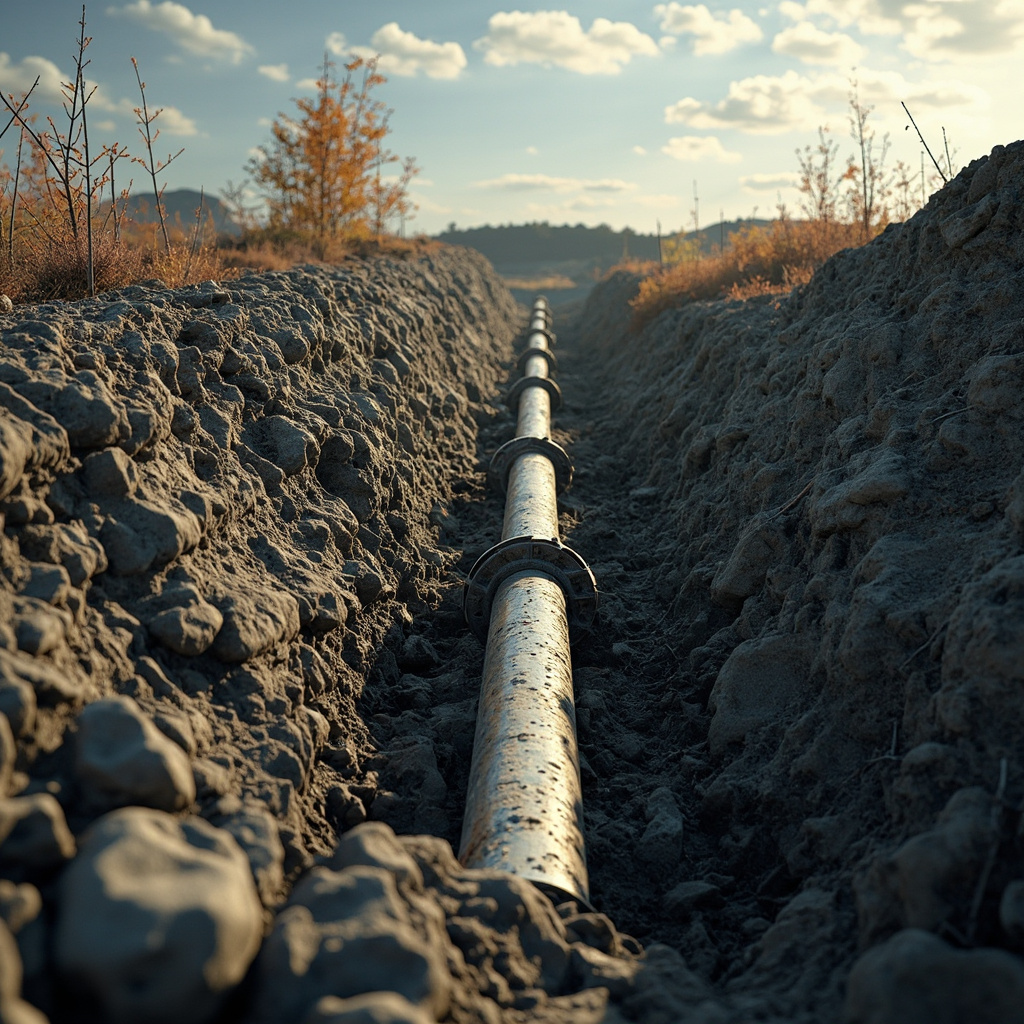
Coating systems for buried oil and gas pipelines, port steel pipe piles, and the underwater portions of ship hulls must be used in conjunction with cathodic protection (CP). The coating provides 99% barrier protection, while cathodic protection compensates for the 1% at coating pinholes and damage sites. However, cathodic protection itself is a double-edged sword: when the protection potential is too negative (more negative than -1.1V vs Cu/CuSO₄), the large amounts of OH⁻ and H₂ generated by the cathodic reaction will destroy the chemical bonding between the coating and the substrate, leading to coating cathodic disbondment (CD). Precise control of the CD rate and the design of sacrificial anode layout are the core technical challenges in coating + CP combined protection engineering.
I. Relationship between Cathodic Protection Potential and CD Rate
| Protection Potential (V vs Cu/CuSO₄) | Coating Type | CD Disbondment Radius (mm/30d, ISO 15711) | Protection Status |
|---|---|---|---|
| -0.85 (minimum protection potential) | Epoxy (FBE fusion bonded epoxy) | 2-4 | Insufficient protection — steel may begin to corrode |
| -1.00 | Epoxy (FBE) | 5-8 | Adequate protection — moderate CD rate |
| -1.10 | Epoxy (FBE) | 8-15 | Sufficient protection — CD rate begins to increase |
| -1.20 (overprotection) | Epoxy (FBE) | 15-30 | Overprotection — severe CD, coating life sharply reduced |
II. Overview of Technical Parameter Comparison
| Technical Indicator | Standard Requirement | Premium Level | Test Method |
|---|---|---|---|
| Adhesion | ≥3MPa | ≥5MPa | ISO 4624 Pull-off Method |
| Salt Spray Resistance | ≥500h | ≥1000h | ASTM B117 |
| Weathering Resistance (QUV) | ≥1000h gloss retention >50% | ≥3000h gloss retention >80% | ISO 16474-3 |
| VOC Content | Compliant with GB standard | 50% below limit | GB/T 23985 |
| Application Window | 5-35°C | -10~40°C (wide temperature range) | TDS Recommended Conditions |
II. Calculation of Sacrificial Anode Configuration
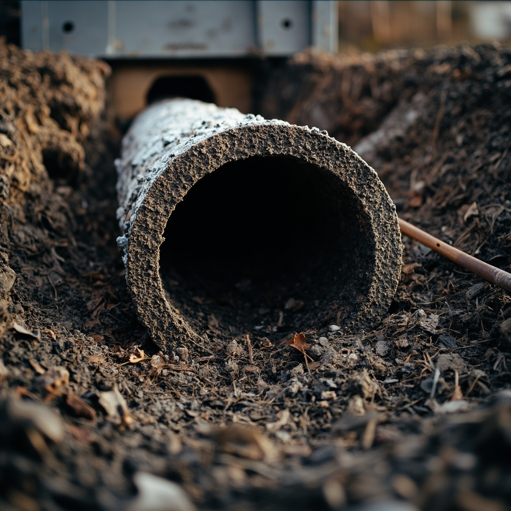
Taking a buried steel pipeline (diameter 500mm/length 10km/3PE coating) as an example, calculate the layout spacing of sacrificial anodes (magnesium anode/14.5kg/each): Anode spacing (m) = anode output current (A) × design life (years) × utilization rate (0.85) / (protective current density (A/m²) × pipeline external surface area (m²)) × number of anodes. For a design life of 25 years, replace when the initial coating damage rate reaches 85%.

Technical deepening: systematic optimization methods for process parameters (DOE experimental design)
The optimization of coating production processes should not rely on the "trial-and-error method" but should adopt the scientific method of DOE (Design of Experiments). Taking the dispersion process as an example—factors affecting quality (linear velocity/time/filling rate/temperature), 4 factors each at 3 levels—a full factorial requires 81 experiments—DOE uses orthogonal experiments L9 (9 times) or response surface methodology (27 times) to greatly reduce the number of experiments—while simultaneously obtaining the main effects and interactions of each factor. For example, it is found that "the interaction of linear velocity × time is significant": high linear velocity + short time and low linear velocity + long time can achieve the same dispersion effect—but the former saves over 20% energy.
In DOE analysis, interpretation of the P-value — P95% confidence). DOE ultimately outputs a set of prediction models (polynomial regression equations) — input line speed/time/temperature → predict fineness/viscosity/gloss — providing formulation engineers with a "digital formulation optimization" tool.
Industry practice: from "master craftsman's feel" to "parameter standardization"
The common challenge in the coatings industry — when experienced veteran workers retire, their "feel" (mixing resistance / fineness gauge scraping / visual inspection of wet film gloss) is taken away — new employees cannot replicate it. Transform the "feel" into quantifiable standard parameters (1) mixing resistance → viscometer reading; (2) fineness gauge scraping → fineness gauge reading (μm); (3) wet film gloss → gloss meter (GU value). The "standard parameter card" for each process is posted next to the equipment — new employees operate according to the "card" rather than "by feel". "Parameter standardization" is a key step for coating factories to move from "workshop" to "factory".
FAQ
Q1: What is the specific method for Coating Disbondment (CD) test (ISO 15711)?Drill a 6mm diameter artificial defect hole through the coating to the steel substrate → immerse the panel in 3% NaCl solution → apply a constant potential of -1.5V (to artificially accelerate CD) → remove after 30 days → radially peel the coating from the defect hole center using a blade → measure the radius of the disbonded area (mm). CD radius <8mm is excellent (requirement for buried pipeline coatings per ISO 21809-1 Annex G).
Q2: Why are 3PE (3-layer polyethylene) and FBE (fusion-bonded epoxy) the two mainstream coatings for buried pipelines?3PE——bottom layer epoxy powder (FBE) + middle copolymer adhesive layer + outer layer polyethylene (PE), combining FBE's high adhesion (>10MPa) and PE's high mechanical strength / low water vapor transmission rate. FBE single layer——lower cost than 3PE (about 50%-70%), faster construction speed (powder electrostatic spraying online one-time forming), but mechanical impact resistance weaker than 3PE. Large-diameter long-distance pipelines (>24inch) use 3PE, small-diameter (<12inch) and field joint coating use FBE or liquid epoxy.
Q3: How does the defect rate of buried pipeline coatings evolve over time?Initial defect rate <1% (small pinholes generated during construction + scratches from transportation and lifting). After 10 years of service, the defect rate rises to 2%-5% (pressure damage from backfill rocks + soil settlement stress + third-party excavation damage). After 20-30 years of service, the coating ages and becomes brittle, and the defect rate accelerates to 5%-15%. The coating defect rate is the most critical parameter determining the anode protection current density and anode consumption rate—for every 1% increase in defect rate, the anode consumption rate roughly doubles.
Q4: How is EIS (Electrochemical Impedance Spectroscopy) used to monitor the combined performance of coating/CP?EIS is a non-destructive method: install EIS probes at test post locations along the pipeline (usually near the anodes) → periodically (annually) measure coating impedance (|Z| at 0.01 Hz). |Z|>10⁹ Ω·cm² — coating excellent (very few defects); |Z|=10⁷-10⁹ — coating good (slight aging); |Z|=10⁵-10⁷ — coating significantly aged, need to increase anode output or schedule maintenance; |Z|<10⁵ — coating essentially failed, need immediate repair or pipe section replacement.
Q5: How to choose between sacrificial anodes and impressed current (ICCP)?Sacrificial anodes (magnesium/zinc anode rods) — no external power required, simple maintenance, no stray current interference with neighboring pipelines, suitable for small/short-distance pipelines (<50km) and soil resistivity <50Ω·m; Impressed current (ICCP) — suitable for long-distance pipelines (>50km) and high soil resistivity scenarios. 3PE+FBE pipelines typically adopt a hybrid scheme of sacrificial anodes + ICCP — ICCP provides baseline protection, and sacrificial anodes provide backup protection during ICCP failure/power outage.
Q6: Impact of different soil types on anode layout?Low-resistivity soil (50Ω·m, sandy soil/rock)——anode spacing needs to be reduced to 50-100m and special backfill material (a mixture of gypsum + bentonite + sodium sulfate wrapping the anode) must be used to lower the grounding resistance. Soil with pH<4 (acidic swamp) will accelerate magnesium anode consumption (consumption rate increases by 2-3 times), so zinc anode substitution should be considered.
Q7: What are the differences in coating CD between marine and buried environments?Marine environment: (1) Seawater is a good electrolyte (conductivity >100 mS/cm) — CP current distribution is more uniform / CD tendency is relatively small; (2) Biofouling (barnacles / algae) — their metabolic products (sulfides) accelerate coating degradation. Buried environment: (1) Soil conductivity is non-uniform — uneven CP current distribution leads to local over-protection / under-protection; (2) Scratches from stones in soil + sulfides produced by anaerobic bacteria (SRB sulfate-reducing bacteria) — synergistic damage to the coating.
Q8: Why is the pipeline field joint coating the "weakest link" in the coating system?Factory-prefabricated 3PE/FBE coatings are completed before the pipeline leaves the factory—the quality of the pipe body coating is controllable. However, the weld area (Field Joint) after on-site welding of the pipeline is coated in the field—requiring sandblasting + primer + anti-corrosion layer application under wild field conditions—where the environment (wind, rain, dust, temperature, and humidity) cannot be controlled as in a factory. The performance of field joint coatings is typically 20%–30% lower than that of factory coatings. The field joint area is also where CD disbondment and pipeline corrosion leakage occur most frequently—the control of field joint quality is the key to the success or failure of pipeline anti-corrosion engineering.
Q9: How to detect the integrity of buried pipeline coatings?(1)PCM (Pipeline Current Mapping) — detect the current attenuation in the pipe along the pipeline path on the ground — locations with rapid current attenuation = severe coating damage; (2)DCVG (Direct Current Voltage Gradient) — locate coating damage points using the potential difference gradient between two reference electrodes on the ground (accuracy <1m); (3)CIPS (Close Interval Potential Survey) — sample the pipe-to-soil potential every 1-5m along the pipeline path to assess CP protection adequacy — potential -0.85V = insufficient protection (NACE SP0169 standard).
Q10: Coating refurbishment strategy for old pipelines?Complete replacement (excavation + old coating removal + new coating) — extremely high cost (>1000 RMB/m), only used for severely corroded sections with frequent leaks (consider when 20% and leak frequency >1 time/km·year). Upgrading the CP system of old pipelines (adding anodes / converting to ICCP) is more economical than coating refurbishment — CP can compensate for the effects of partial coating aging.
Related Reading
Summary
The cathodic disbondment (CD) rate of immersed/buried coating systems is controlled by the protection potential (-0.85 to -1.1 V vs Cu/CuSO₄)—overprotection (15 mm/30 d) and shortened coating service life. Sacrificial anode configuration is calculated based on protection current density, design life, and coating damage rate—3PE pipelines recommend anode spacing of 100–300 m / 25-year life. EIS (impedance >10⁷ Ω·cm²) and PCM/DCVG/CIPS (pipeline route detection) constitute a complete technical chain for coating integrity monitoring. Kexin New Materials provides technical support for the joint design of 3PE/FBE coatings + cathodic protection to buried and marine pipeline customers.