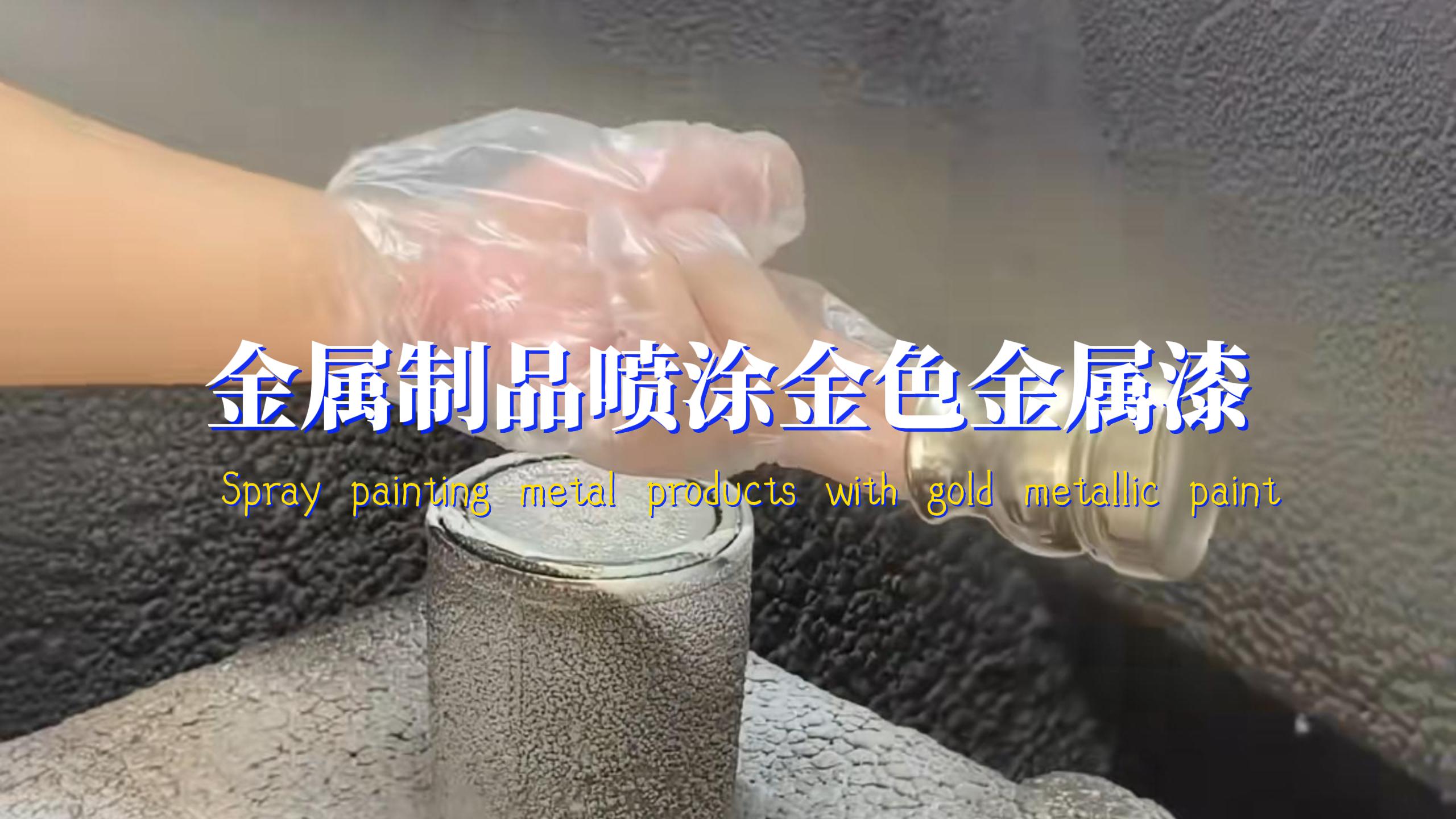
Laser cleaning (laser surface cleaning in GB/T 41735-2022) is the process of removing contaminants and unwanted material from a workpiece surface with a laser beam: the contaminant absorbs the beam energy and, within a very short time, heats up, melts, vaporises or expands, while interfacial thermal stress, the ablation plume and the plasma shockwave detach rust layers, mill scale, old coatings, plating or organic soil from the substrate without introducing abrasive, water or chemical waste. As a coating pretreatment it is a cleanliness tool, not an anchor-profile tool - it delivers a high-purity surface, and mechanical keying has to be engineered through parameter design or a follow-up pass.
A familiar rework story runs like this: old paint and light rust on an equipment platform and its handrails are removed locally with the laser and overcoated; the operator sees bare metal, photographs it for the record, accepts the surface against the blasting Sa2.5 photographs and releases it to the next trade. Three months later the top coat blisters along the edge of the repair; the pull-off face looks clean, yet a dull conversion film remains at the interface and the pull values sit clearly below the surrounding original coating. The cause is rarely that the laser left the surface dirty - it is three things that were not done: oil and soluble salts never went through chemical cleaning and a Bresle retest; the fluence of the passes stopped near the cleaning threshold instead of being fixed by threshold tests on this batch of rust thickness; and 'no anchor profile' was treated as 'surface accepted', with no re-check of the coating system and dry film thickness against the measured roughness. GB/T 41735-2022 brings the cleaning of contaminants before coating preparation into its scope of application and requires that, when laser cleaning precedes coating, surface roughness be verified against the process requirements of the following step - precisely the sentence rework crews tend to skip.
TL;DR: conclusions first
- Fluence is the primary criterion: clause 6.3.3 of GB/T 41735-2022 converts average power P (W), spot area S (cm²) and repetition rate F (Hz) into E (J/cm²), and clause 6.3.4 requires measuring the cleaning and damage thresholds, with the working point placed in the valid interval 30 % below the damage threshold.
- The window from published tests: a pulsed Nd:YAG at 11 J/cm² over 20 passes fully removes a dense rust layer of about 80 μm (±40 μm); below 5 J/cm² even more than a hundred passes achieves nothing.
- Roughness is not free: de-rusting alone leaves Rz below 70 μm; one texturing pass at 629 mm/s with 94.1 % overlap brings Rz to about 74 μm, reaching the anchor range commonly specified for heavy-duty systems, while excessive overlap can push Rz toward 300 μm.
- Soluble salts are the laser's strongest card: the three texturing conditions of one test series measured NaCl equivalents of 0.87 mg/m², 1.80 mg/m² and 3.43 mg/m², far below the customary 50 mg/m² acceptance ceiling, while grinding and wire-brush blasting press salt into the surface, reading near the limit or at twice it.
- Adhesion is read by failure mode: under ISO 4624 pull-off, laser surfaces inside the process window and vacuum-recovered blasted surfaces fail mostly cohesively in the coating or adhesive layer, while ground and wire-brushed surfaces show a higher share of adhesive interface failures and lower mean values.
- Oil and thick rust are not in the same class: the standard requires heavy oil deposits to be pre-treated to reduce thickness with power adjusted to avoid flame, thin-wall and mesh parts to be cleaned at low power over several passes, and uneven coating thickness handled the same way or cleaned locally in the thick zones.
- Capacity follows the areal rate: about 0.15 cm²/s at 100 W, 0.3 cm²/s at 200 W and 0.66 cm²/s at 1000 W (2 min to 3 min per 100 cm²), equal to roughly 0.054 m²/h, 0.108 m²/h and 0.24 m²/h - heavy rust over large areas still belongs in the blasting schedule.
The four pathways by which a laser removes contaminants
Each of the four removal pathways suits a different contaminant. Vaporisation and ablation: where the contaminant absorbs the laser better than the substrate, its top layer is heated to evaporation on a nanosecond timescale and the vapour pressure ejects the loosened material - well matched to organic coatings and thin oxide films. Thermal-shock spallation: oxide and metal expand differently, and the rapid temperature swing puts shear stress into the interface until firmly bonded mill scale releases in sheets. Plasma shockwave: ablated material is further ionised into a plasma plume whose expansion drives a shockwave that sweeps already-detached particles away from the surface and reduces redeposition. Selectivity: wavelength and pulse width decide which layer gets to absorb energy, and that is what makes paint removal without substrate damage possible at all. In engineering practice these four effects collapse into one measurable quantity - cumulative energy per unit area, the fluence set by pass count and overlap rate. GB/T 41735-2022 classes its cleaning targets as Class I metal oxides and plating, Class II coatings and Class III specific contaminants: a taxonomy of removal pathways, not of how dirty the part looks.
Rust is relatively easy, oil is hard, soluble salts go their own chemical and Bresle route
Rust is relatively easy because iron oxides absorb around 1064 nm more strongly than the steel beneath, so energy is deposited first in the rust and at its interface. Oil behaves the opposite way: an oil film is only microns thick and a weak absorber, so energy is reflected or transmitted, and the liquid film spatters under instantaneous heating, spreading into a thinner, more uniform contamination layer that looks cleaned yet wets even worse. That is why clause 7.2.4 of GB/T 41735-2022 requires heavy oil deposits to be pre-treated to reduce their thickness, with cleaning power adjusted so no flame forms; on site, read it as chemical degreasing first, laser finishing second - the chemical route and bath control are covered in Paint pretreatment chemistry: alkaline degreasing, acid pickling, conditioning, phosphating, passivation and silane. Soluble salts are the third category: chlorides and sulphates are non-volatile, and heat-driven desorption removes only part of them. Published research on the chloride-bearing rust phase β-FeOOH:Cl⁻ gives a rust-removal threshold of 8.3 J/cm² and a Cl⁻ desorption threshold of 2.6 J/cm² - two unequal numbers, proving that de-ironing and de-salting follow different mechanisms, so 'we ran 20 passes' cannot be used to infer that the salt is compliant; sampling, conversion and limits are in Soluble salt contamination of coating substrates: Bresle sampling, conductivity judgement and limits.
Fluence: from one formula to two thresholds
Clause 6.3.3 of GB/T 41735-2022 expresses laser fluence E (J/cm²) through average power P (W), working spot area S (cm²) and pulse repetition rate F (Hz): the single-pulse energy equals P divided by F, and dividing that by the spot area yields E. At 100 W, 100 kHz and an effective spot diameter of 0.1 mm (an area of about 0.008 mm²) the pulse energy is 1 mJ, corresponding to roughly 12.7 J/cm² - the same order as the publicly measured 12.7 J/cm² delamination-onset threshold for oxide layers on TWIP steel, which is why quoting power alone is meaningless: spot size and frequency must be reported with it. Clause 6.3.4 then defines the threshold test: the value at which the layer to be removed starts diminishing is the lower cleaning threshold, the value at which the substrate itself starts being consumed is the upper damage threshold, and effective removal with no visible substrate damage in between is the effective cleaning range; the standard recommends placing the working point inside that interval, on the side 30 % below the damage threshold. The engineering consequence: every project needs threshold coupons run on the actual material and actual rust thickness, and the informative Annex A recommendations were obtained on a 100 W pulsed fibre laser - they cannot serve as a process card for someone else's machine; measured reference on thick rust is in Surface preparation for coating over rust: St2/St3 cleaning, rust layer grading and conversion priming.
| Substrate and contaminant | Parameter meaning | Value | Published source |
|---|---|---|---|
| Oxide layer on TWIP steel | Cleaning threshold (delamination onset) | 12.7 J/cm² | Hot Working Technology 2024, 53(16) |
| Oxide layer on TWIP steel | Evaporation-dominated ablation | 38.2 J/cm² | same as above |
| Oxide layer on TWIP steel | Damage threshold (substrate oxidation) | 50.9 J/cm² | same as above |
| Chloride-bearing rust β-FeOOH:Cl⁻ | Rust-layer removal threshold | 8.3 J/cm² | Applied Physics A (2026) |
| Chloride-bearing rust β-FeOOH:Cl⁻ | Cl⁻ desorption threshold | 2.6 J/cm² | same as above |
| Heavily corroded S355 structural steel | Effective de-rusting process point | 11 J/cm² × 20 passes | Fraunhofer IFAM trial |
| Heavily corroded S355 structural steel | No-effect lower bound | below 5 J/cm² | same as above |
| Loose rust on Q235 carbon steel | Optimised energy density | 7.6 J/cm², scan speed 900 mm/min | Laser Technology 2021, 45(4) |
| Q345C steel pipe pile, 100 μm rust layer | Optimised parameters and result | 53 W, 80 kHz, 5555 mm/s, removal rate 91.37 % | Surface Technology 2019, 48(11) |
| Q345qD with 200 μm rust layer | Two-pass optimised parameters | 161.56 W, 721.97 mm/s, 100 kHz | Municipal Technology 2025, 43(2) |
Parameter coupling and passes: how narrow the working window really is
The parameters are coupled, but the problem simplifies into two adjustable quantities: pulses per unit area, and energy per pulse. Scan speed v and repetition rate F set the pulse spacing (v divided by F); in the published Fraunhofer IFAM trials, 629 mm/s, 823 mm/s and 1070 mm/s correspond to pulse spacings of 6.29 μm, 8.23 μm and 10.70 μm, and pulse spacing divided by spot diameter gives the overlap rate - 94.1 % at level L1 of that study. Overlap and single-pulse energy together set the cumulative fluence, which decides whether the surface is cleaned or re-melted. The window in the same study is narrow: below 5 J/cm² nothing works even after more than a hundred passes, while 11 J/cm² over 20 passes removed a dense corrosion layer of about 80 μm (±40 μm) completely. Too many passes or too much overlap produce re-melting and secondary oxidation; the 2025 optimisation of heavily rusted Q345qD reported in Municipal Technology shows the same trend - high fluence combined with high overlap damages the substrate, scan speed is the significant variable, and two passes (161.56 W, 721.97 mm/s, 100 kHz) are safer than one (257.75 W, 500 mm/s, 100 kHz). Throughput follows from the same parameter set: about 0.15 cm²/s at 100 W, about 0.3 cm²/s at 200 W and about 0.66 cm²/s at 1000 W (2 min to 3 min per 100 cm²).
Why aluminium alloys and galvanised layers sit in a narrower window
On substrates other than carbon steel the window is generally narrower, for reasons of melting point and reflectivity. Zinc melts at about 419.5 ℃ and boils at about 907 ℃, aluminium at about 660.3 ℃, while the solidus of carbon steel lies above 1300 ℃; near-infrared light reflects strongly off clean metal, so energy must be absorbed by the contaminant first and conducted downwards - and once the rust is thinned past a critical value, the next pass starts melting the layer beneath. Burn-through of a galvanised coating ends its sacrificial protection, and cut edges and weld spots are the most exposed; aluminium alloys develop localised re-melting and softening at over-processed points. Hence low power over several passes for thin-wall and mesh parts (clause 7.2.3 of GB/T 41735-2022), the same rule or locally targeted cleaning where coating thickness varies (7.2.5), and inert-gas shielding for oxidation-prone materials (7.2.6). Verification lands on microstructure: examine the cross-section at no less than 500x optical magnification or in a scanning electron microscope - no re-melted layer of micron scale, and no microstructural transformation. The overall approach to dissimilar substrates and old coatings is in Different treatment plans for bare metal, old paint and plastic substrates.
Benchmarks against blasting, power tooling and grinding
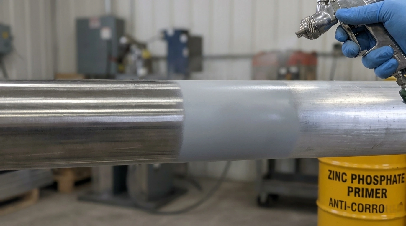
The comparison with conventional pretreatment should be read on four counts. Cleanliness: ISO 8501-1 gives visual grades after blasting and power tooling (Sa1 to Sa3, St2 and St3); there is no dedicated cleanliness grade for laser cleaning, so sites routinely borrow the Sa photographs - state that convention in the technical agreement, or the same surface will be rated two different ways, and Industrial coating surface preparation: Sa2.5 blasting, roughness and dew-point control and Paint surface preparation: Sa2.5 and blast cleaning grades develop the Sa rating conditions in more detail. Anchor profile: blasting cuts an angular profile by abrasive action - vacuum-recovered blasting reached an Rz of about 93 μm in the cited study; the laser forms rounded micro-cavities with undercuts through re-melting, giving Rz below 70 μm after de-rusting alone and about 74 μm after one 629 mm/s texturing pass; the same Rz number does not carry the same meaning for peak coverage or wetting under the two profiles, and an over-deep anchor leaves thin-coat spots on the peaks. Salts: mechanical methods tend to press salts into the surface - after grinding, readings approach or exceed 50 mg/m², and wire-brush blasting reaches about twice the acceptance limit, while the three laser texturing conditions in the same test series measured 0.87 mg/m², 1.80 mg/m² and 3.43 mg/m². Secondary waste and constraints: blasting generates spent abrasive, dust-collector contents and a media recovery system to be characterised and disposed of under local solid-waste rules; the laser creates almost no secondary waste, but its fume must be captured and a laser-safe enclosure established.
| Method | Roughness Rz | Soluble salts (NaCl equivalent) | Pull-off failure mode | Site constraints |
|---|---|---|---|---|
| Laser: de-rusting + 629 mm/s texturing | about 74 μm | 0.87 mg/m² (±0.60) | mainly cohesive failure in the coating | narrow window, low areal rate |
| Laser: de-rusting + 823 mm/s texturing | about 58 μm | 1.80 mg/m² (±1.22) | mixed cohesive and adhesive | low profile - re-check the system schedule |
| Laser: de-rusting + 1070 mm/s texturing | about 10 μm | 3.43 mg/m² (±3.30) | rising share of adhesive failure | close to an anchor-free surface |
| Vacuum-recovered blasting | about 93 μm | at or below 50 mg/m² | mainly cohesive failure in the coating | media recovery, spent abrasive, dust |
| Angle grinder with sanding paper | clearly below blasting | approaching or above 50 mg/m² | more adhesive interface failure | operator-dependent, salt re-embedment |
| Wire-brush blasting (about 2000 min⁻¹) | low | about twice the acceptance limit | more adhesive interface failure | presses salt in instead of removing it |
Does adhesion come from cleanliness or from roughness?
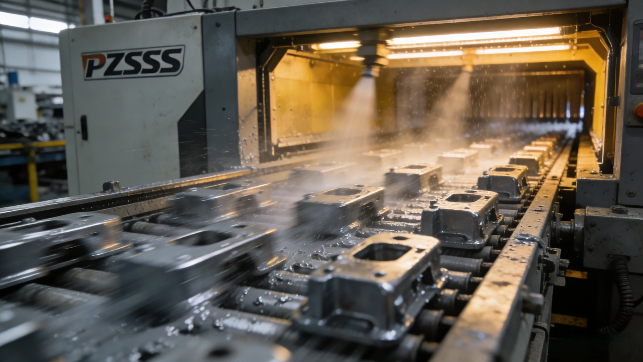
The adhesion evidence explains more than a bare number does. The same study measured repair-coat pull-off adhesion to ISO 4624: laser surfaces inside the process window and the vacuum-recovered blast profile mostly failed cohesively within the coating or the adhesive layer, while grinding and wire-brush blasting showed a higher share of adhesive interface failure and lower mean values - inside the laser window, adhesion is won on cleanliness, not on roughness. From this a workable acceptance rule follows: when the low dry film thickness allowed by the specified system cannot cover the profile peaks, a deep anchor profile is itself a defect source, and a very clean surface at moderate Rz is more likely to reach design performance; when Rz is too small, the mechanical interlock area drops, which hurts heavy-build systems and zinc-rich primers - the cathodic protection of a zinc-rich layer depends on conductive contact between zinc dust and steel, and residual oil or residual rust breaks that path. Probe placement, dolly size and failure-mode reading for the pull-off test are in Adhesion acceptance for protective coatings: pull-off test values and failure modes; the matching film-thickness and holiday acceptance is in Coating project acceptance: ISO 12944 and SSPC-PA 2 film thickness and holiday testing.
Surface free energy and wetting: what contact angles and dyne levels can tell you
Cleanliness has one more measure that is frequently overlooked: surface free energy. Published data place metal oxides far above polymers - iron oxides in the hundreds of mJ/m², anodised aluminium at about 169 mJ/m² - while a residual oil film crushes the effective surface energy below a few tens of mJ/m², and coating wetting deteriorates accordingly. The fast site proxies are dyne levels and contact angle: the common published rule-of-thumb threshold for general painting and printing lies between 38 mN/m and 42 mN/m, high-bond applications take 46 mN/m or more, and full wetting is approached only as the contact angle tends toward 0°. One caution: the laser leaves an active clean surface - fresh metal and oxide adsorb atmospheric hydrocarbons quickly and begin to flash-rust - so the interval between cleaning and coating must be written into the procedure, and the blasting habit of several open hours does not transfer. Dyne pens and contact-angle readings are process aids; acceptance rests on the standard methods and their formal text.
Making pre-coating acceptance work: the four-item retest list
Acceptance should be organised around the question of which parameters must be re-measured. Cleanliness: visual comparison against ISO 8501-1, recording which borrowed Sa convention applies. Soluble salts: to ISO 8502-6 and ISO 8502-9 - patch area 1250 mm², sample volume 3 ml, conversion constant c = 5 kg·m⁻²·S⁻¹, ρA = c × 10² × V × Δγ / A; at Δγ = 20 µS/cm this gives ρA = 24 mg/m², blank readings should not exceed 5 µS/cm, and results are normalised to 25 ℃. Fix one dwell time: ISO 8502-6:2020 prescribes 10 min while SSPC Guide 15 allows as little as 90 s, and mixing them on one job yields incomparable data. Roughness by stylus profilometer (ISO 4287, λc = 8 mm, ln = 40 mm) or replica tape (ISO 8503 series, GB/T 13288.1); clause 8.3.3 of GB/T 41735-2022 requires roughness to be tested against the following process when cleaning precedes coating, and, when cleaning is the final step on the part, the roughness grade should not shift by more than one class. Adhesion to ISO 4624 / GB/T 5210, under which the bond strength of a coating re-applied after cleaning must not fall below the value before coating removal - the clause that turns 'the repair zone tests lower than the original area' into an outright fail. Table 3 gives the mandatory retest matrix; the project-level acceptance workflow and instrument practice are in Coating project acceptance: ISO 12944 and SSPC-PA 2 film thickness and holiday testing, and the salt judgement detail in Soluble salt contamination of coating substrates: Bresle sampling, conductivity judgement and limits.
| Indicator | Method or standard | Retest after cleaning? | Basis of judgement |
|---|---|---|---|
| Visual cleanliness | ISO 8501-1 comparison photographs (no laser-specific grade) | Mandatory | No visible rust, old coating or soil, with the borrowed Sa grade convention stated |
| Soluble salts | ISO 8502-3 field test kits, ISO 8502-6 and ISO 8502-9 | Mandatory | Customary ceiling 50 mg/m²; marine and immersion service judged around 20 mg/m² |
| Roughness Rz and Ra | ISO 4287 stylus, ISO 8503 replica, GB/T 1031 | Mandatory | Re-melted micro-cavities are not an angular anchor; check against low DFT and peak-to-valley coverage |
| Oil and residual organics | Solvent wipe, UV fluorescence, contact angle or dyne level | Mandatory | Do not expect the laser alone to remove oil; chemical degreasing comes first |
| Adhesion | ISO 4624 / GB/T 5210 pull-off | Mandatory after recoating | Not below the value before coating removal, with the failure mode recorded |
| Heat effect and re-melted layer | Optical microscope at 500x minimum or SEM cross-section | Sampled | No re-melted layer of micron scale, no microstructural transformation |
| Dry film thickness and holidays | ISO 19840, SSPC-PA 2, spark tester | Per system | An over-deep anchor raises paint consumption per square metre and leaves thin spots on the peaks |
Beyond the window: wavelength, pulse width and selectivity
Wavelength and pulse width decide how far selectivity can realistically go. 1064 nm (Nd:YAG and fibre lasers) is absorbed well by rust and oxides and reflected strongly by bare metal - the mainstream of industrial cleaning; 532 nm and 355 nm raise absorption in organic coatings, polymers and residues while shrinking the thermal impact, for precision parts and thin films. Pulse width sets the depth of heat diffusion: nanosecond pulses are thermally active, while picosecond and femtosecond pulses approach cold ablation - a small heat-affected zone, paid for in capital cost and cycle time. Published vendor application guides bin fluence roughly in three tiers: limited cleaning capability below 1 J/cm², most common contaminants covered between 1 J/cm² and 5 J/cm², thick layers above 5 J/cm² with a risk of substrate damage - a scoping rule of thumb that is not equivalent to the measured thresholds above. Repetition rate and scan speed must always be adjusted as a pair: raising the rate lowers single-pulse energy yet raises cumulative heat input, and capacity bought by simply 'turning up the power' is often paid for with re-melting and secondary oxidation. How substrate type and old-coating condition steer the cleaning strategy matches the substrate classification approach in Different treatment plans for bare metal, old paint and plastic substrates.
Temper colours, pass striping and flash rust
Three visible signals deserve to be read correctly. Temper colours: blue, purple or yellow interference tints in the cleaned zone come from thin oxides grown by local overheating - a hint of over-processing, not proof of damage, which is settled by microstructure and adhesion testing. Pass striping: insufficient pulse spacing or overlap leaves parallel bands and uncleaned lines; inspect with side or low-angle light, never head-on, and expect the top coat to amplify these stripes afterwards. Flash rust: the active clean surface produced by the laser flash-rusts in high humidity at a rate no slower than a blasted one, so the general rule stands - keep the substrate temperature 3 ℃ above the dew point, within clause 5.2.1 of GB/T 41735-2022, which advises an ambient temperature of 5 ℃ to 30 ℃ and relative humidity no greater than 75 %; the full dew-point and conditioning treatment is in Industrial coating surface preparation: Sa2.5 blasting, roughness and dew-point control, and the chemical-pretreatment alternative in Paint pretreatment chemistry: alkaline degreasing, acid pickling, conditioning, phosphating, passivation and silane.

Output and the cost ledger: consumable-free is not cost-free
Convert the areal cleaning rate into output and the conclusion is blunt: 0.15 cm²/s at 100 W equals about 0.054 m²/h, 0.3 cm²/s at 200 W about 0.108 m²/h, and 0.66 cm²/s at 1000 W about 0.24 m²/h. That is not in the same order of magnitude as the per-square-metre pace of open blasting, which is why the economically sound position for the laser is 'small areas, many constraints': partial rework on in-service structures, no-dismantling work, confined spaces, precision parts and automated spot cleaning. The cost ledger must be complete: capital depreciation and optics wear, electricity for the laser source plus chiller and dust extraction, fume capture and filter-media replacement, exclusion measures and training hours, downtime and takt losses; on the other side of the comparison, blasting carries abrasive consumption, compressed air, media recovery and dust collection, spent-media disposal and containment. Consumable-free does not mean cost-free: the quotation and the technical agreement should list both cost stacks separately, and acceptance should be judged on film thickness and holidays per Coating project acceptance: ISO 12944 and SSPC-PA 2 film thickness and holiday testing, not on which machine happened to be used.
Occupational health and environmental safety
Laser cleaning transfers contamination from the surface into the gas phase - it is not zero-emission. The ablation plume carries metal-oxide particles in the ultrafine size range, and burning off old coatings and plating can additionally release halogenated products, isocyanates and heavy metals depending on the coating system; the governing evidence is the product safety data sheet plus on-site measurement, not assumptions. Controls in priority order: enclosure and local exhaust, cross-flow airflow or source capture (clause 7.2.7 of GB/T 41735-2022), fume treatment units and filter management, with respiratory protection where still required. On the radiation side the standard normatively cites GB 7247.1-2012 (safety of laser products - equipment classification and requirements) together with GB/T 18490.1 and GB/T 18490.2 (safety of machinery - general requirements for laser-processing machines and requirements for handheld laser-processing machines), and it requires the beam path to be fully enclosed or protected, laser safety glass on the workstation against reflections, safety signage placed per GB 2894 with fences, walls or screens keeping unauthorised persons out of the hazard zone, and a clean, ventilated workplace; operators must complete process, equipment and safety training and pass assessment before working. Emission measurement methodology follows ISO 19973-1:2015 for sampling and measuring particle and gas emissions from laser processing. Pulsed ablation also produces impact noise; assess it against local occupational exposure limits.
Where laser cleaning fits and where it does not
Six settings suit the laser: partial rework on in-service structures without production shutdowns; no-dismantling work and confined spaces around weld seams, pipe supports, handrails and flange faces; automated spot cleaning of precision parts on production lines before welding, assembly or coating preparation; selective stripping of old coatings and layer-by-layer removal of multilayer systems; areas constrained by abrasive embedment, waste water or cross-contamination; and restricted-space jobs that require secondary waste to be kept low. Six exclusions are equally clear: large workpieces under thick laminate rust, where areal rate and power consumption never pay back; oil-flooded surfaces without prior chemical degreasing, where the laser only spreads the oil; heavy-build or zinc-rich systems needing a stable angular anchor profile, where laser texturing consistency and re-melted micro-cavities still lack long-term service data; badly salt-contaminated work where on-site Bresle retesting is impossible; and open-air crossing operations without laser exclusion or fume capture. The criterion is never how modern the technology looks; it is whether, for this material, this contaminant and these constraints, cleanliness, roughness, salt load and adhesion can all be accepted at once.
Common failure modes and rework paths
Six failure modes, each arranged as symptom - criterion - action. Blistering at the repair boundary with low pull-off values: usually salt or oil left behind - retest by Bresle, go back to chemical degreasing and re-do, adding a mechanical keying pass if needed. Cratering and local flooding of the top coat: residual organics spread thin by the laser - re-check by solvent wipe and rerun the degreasing route in Paint pretreatment chemistry: alkaline degreasing, acid pickling, conditioning, phosphating, passivation and silane. Blue or interference colours together with scattered adhesion results: overheating and secondary oxidation - lower the fluence or split into more passes, and re-verify defocus, scan speed and overlap rate. Parallel bands and uncleaned lines: pulse spacing and overlap short of target - recompute the spacing as scan speed ÷ repetition rate, then re-check the spot diameter. Flash rust after cleaning: the hold-time and dew-point control failed - shorten the clean-to-coat interval, condition the environment per 5.2.1, and pull the first coat forward. Locally burned-through galvanising: the window was misjudged - switch to low power over more passes or to a mechanical method, and re-inspect the zinc layer at cut edges and around welds. Every action needs a record: fluence and pass count, retest data, photographs of the failure interface, and the threshold to watch next time.
Key figures at a glance, with units
- Fluence conversion: pulse energy = P ÷ F, E (J/cm²) = pulse energy ÷ S; at 100 W, 100 kHz and an effective spot diameter of 0.1 mm (about 0.008 mm²) this gives about 12.7 J/cm².
- Process window: 11 J/cm² × 20 passes removes a dense corrosion layer of about 80 μm (±40 μm); below 5 J/cm², hundreds of passes do nothing.
- Roughness: Rz < 70 μm after de-rusting alone; Rz ≈ 74 μm after a 629 mm/s texturing pass at 94.1 % overlap, about 58 μm at 823 mm/s and about 10 μm at 1070 mm/s; over-processing can reach Rz ≈ 300 μm.
- Soluble salts: NaCl equivalents of 0.87 mg/m², 1.80 mg/m² and 3.43 mg/m² for the three texturing conditions; the customary acceptance ceiling is 50 mg/m², with marine and immersion service judged at around 20 mg/m²; Bresle patch area 1250 mm², detection floor 0.1 mg/m².
- Bresle conversion: ρA = c × 10² × V × Δγ ÷ A with constant c = 5 kg·m⁻²·S⁻¹; V = 3 ml, A = 1250 mm² and Δγ = 20 µS/cm give ρA = 24 mg/m²; blank readings below 5 µS/cm, results normalised to 25 ℃; dwell time 10 min per ISO 8502-6:2020 or 90 s per SSPC Guide 15.
- Threshold spread: TWIP steel oxide at 12.7 J/cm² (delamination onset), 38.2 J/cm² (evaporation-dominated ablation) and 50.9 J/cm² (substrate oxidation damage); chloride-bearing rust β-FeOOH:Cl⁻ at 8.3 J/cm² for rust removal and 2.6 J/cm² for Cl⁻ desorption.
- Areal rate: about 0.15 cm²/s at 100 W (≈ 0.054 m²/h), about 0.3 cm²/s at 200 W (≈ 0.108 m²/h) and about 0.66 cm²/s at 1000 W (≈ 0.24 m²/h).
- Working environment and material limits: GB/T 41735-2022 advises an ambient temperature of 5 ℃ to 30 ℃ and relative humidity no greater than 75 %; zinc melts at about 419.5 ℃ and boils at about 907 ℃, aluminium at about 660.3 ℃, and the solidus of carbon steel lies above 1300 ℃.
Frequent questions on acceptance criteria
Can laser cleaning replace blasting as a coating pretreatment?
Where areas are small and constraints are many, often yes; over large areas of heavy laminate rust, not yet. The comparable evidence is three measurements from one study: after 11 J/cm² × 20 passes the laser took off a dense rust layer of about 80 μm, held soluble salt near 0.87 mg/m², and matched vacuum-recovered blasting on pull-off failure mode; but its areal rate is only 0.15 cm²/s on a 100 W system, about 0.054 m²/h, nowhere near the per-square-metre pace of blasting. The practical answer is a division of labour: laser for partial rework on in-service structures, no-dismantling and confined-space work, and automated spot cleaning of precision parts; blasting or vacuum-recovered blasting for large areas, thick laminate rust and heavy-build systems needing a stable angular anchor profile - with both methods accepted on the same four quantities: cleanliness, Rz, salt load and adhesion.
If Rz after laser de-rusting is too low, can extra passes make up for it?
Yes, but design it as a texturing pass, not as extra de-rusting. The sequence in that study was 11 J/cm² over 20 passes to clean the surface, then a single dedicated texturing scan to build the profile: 629 mm/s produced an Rz of about 74 μm while keeping salt at 0.87 mg/m²; raising the speed to 823 mm/s and 1070 mm/s dropped Rz to about 58 μm and about 10 μm, while salt stayed in single-digit mg/m². Conversely, piling up roughness by slowing the scan and raising the overlap pushes the surface into re-melting: published data show over-processing driving Rz toward 300 μm, and deep cavities trap air that starves the coating on the peaks. Correct practice is to card de-rusting passes and texturing passes separately, verify with a stylus profilometer or replica method to ISO 4287 and ISO 8503, and re-check against the low film thickness and peak-to-valley coverage of the specified system.
Does laser cleaning remove salts, or is Bresle sampling still required?
The laser behaves markedly better on soluble salts than mechanical methods, yet it does not remove the need for retesting. In the same test series the three laser texturing conditions measured NaCl equivalents of 0.87 mg/m², 1.80 mg/m² and 3.43 mg/m², while grinding stayed near or above 50 mg/m² and wire-brush blasting reached about twice the limit - mechanical methods press salt back into the surface. The mechanistic evidence is the pair of unequal thresholds from the chloride-bearing rust study: 8.3 J/cm² to remove the rust and 2.6 J/cm² to desorb Cl⁻, so de-ironing is not de-salting. Keep sampling to ISO 8502-6 and ISO 8502-9: patch area 1250 mm², 3 ml of sample solution, constant 5 kg·m⁻²·S⁻¹, blank no higher than 5 µS/cm, results normalised to 25 ℃; and fix one dwell - 10 min per ISO 8502-6:2020 or 90 s per SSPC Guide 15, never both on the same project.
Can oil simply be burned off with the laser?
Not as the main cleaning step. An oil film is only microns thick and absorbs poorly, so energy is reflected or transmitted; instantaneous heating makes the liquid film spatter into a thinner, more uniform contamination layer that looks bright while lowering surface free energy, and the top coat over it tends to crater. Clause 7.2.4 of GB/T 41735-2022 requires heavy oil to be pre-treated to reduce its thickness, then the cleaning power adjusted to avoid flame, and clause 7.2.3 sets low power over multiple passes for thin-wall and mesh parts. The workable order: solvent wipe or alkaline degreasing to remove the bulk of the oil, the laser afterwards as finishing and de-oxidation, with the chemistry and bath control on the pretreatment page linked above. Do not judge by eye alone - record at least one of a solvent-wipe check, UV fluorescence, or contact angle and dyne level (38 mN/m to 42 mN/m for general work, 46 mN/m or above for high-bond duty).
Why do aluminium alloys and galvanised parts burn more easily?
Because the window is set jointly by melting point, boiling point and reflectivity, not by laser power. Zinc melts at about 419.5 ℃ and boils at about 907 ℃, aluminium at about 660.3 ℃, while the solidus of carbon steel lies above 1300 ℃; at near-infrared wavelengths bare metal reflects strongly and energy reaches the interface only through the contaminant, so once the rust is thinned past a critical point the next pass acts directly on the coating or alloy. The consequences differ as well: burn-through of galvanising ends sacrificial protection, and aluminium parts develop localised re-melting and softening. The standard already lists the countermeasures: low power over several passes for thin-wall and mesh parts (7.2.3), the same rule or localised cleaning of thick zones where coating thickness varies (7.2.5), inert-gas shielding for oxidation-prone materials (7.2.6), and verification on cross-sections at no less than 500x optical magnification or in an SEM, with no micron-scale re-melted layer and no microstructural change. Holding the working point 30 % below the damage threshold is the key safety margin in this scenario.
How soon after laser cleaning must coating begin?
No standard fixes a common number of hours; you set the limit yourself for the active clean surface and write it into the process card. The laser exposes fresh metal and oxide with high surface energy that adsorbs atmospheric hydrocarbons quickly and can flash-rust in high humidity, so simply borrowing the multi-hour tolerance familiar from blasting is inappropriate. Three workable ways to set the limit: constrain it by environment - ambient temperature 5 ℃ to 30 ℃, relative humidity no greater than 75 %, substrate kept 3 ℃ above the dew point; gate it with auxiliary criteria - treat a clear drop in dyne level or rise in contact angle as expired; or verify area by area - clean and coat a small patch first, retest adhesion and failure mode, and derive the allowed interval from the measured result. On rework projects, align the interval with the maintenance window so that no dismantling or housekeeping is inserted between cleaning and the first coat.
How do you recognise over-processing on site?
Read three groups of signals, and treat them as warnings rather than verdicts. Colour: blue, purple or yellow interference tints mean local heating grew a thin oxide film - an overheat flag, but whether real damage occurred is settled by cross-section microstructure. Topography: fluence or overlap that is too high forms re-melted micro-cavities and undercuts; published data show over-processing pushing Rz toward 300 μm, and deep gas-trapping cavities worsen coating wetting; side light reveals the distribution of bright and frosted streaks. Data: falling adhesion means, a rising share of adhesive interface failures, or recoat bond strength below the pre-removal value are all posterior evidence of a window set too high. Act in order: lower the fluence or split into multiple passes, re-check the pairing of defocus, scan speed and overlap rate, then re-run the threshold determination method of GB/T 41735-2022 on fresh coupons - rather than simply adding one more pass.
For adhesion acceptance, does the value matter or the failure mode?
Both, and the failure mode often carries more information. In that study's pull-off results, laser surfaces inside the process window and vacuum-recovered blast surfaces failed mostly cohesively within the coating or adhesive layer, while ground and wire-brush blasted surfaces showed more adhesive interface failures and lower means - which is why the laser satisfies system requirements even at lower Rz. Five acceptance points: select the dolly diameter to match the coating thickness per ISO 4624 / GB/T 5210 and keep good alignment; distribute probes across the repair zone, its boundaries and any suspected heat-affected area rather than only on flat panels; record where the failure plane sits (primer-to-substrate, between layers, cohesive) instead of reporting a single MPa figure; add an explicit rule for repair areas that the recoat bond must not fall below the pre-removal value; and read film thickness, holidays and adhesion together on one acceptance sheet so that no single passing indicator releases the job.
References and basis of the figures
The figures in this article come in three classes. First, formal standard text: GB/T 41735-2022 Green manufacturing - Technical specification for laser surface cleaning (issued and put into effect on 2022-10-12, plan number 20204977-T-469, administered by the National Technical Committee of Green Manufacturing Standardization), plus ISO 8501-1, ISO 8502-3, ISO 8502-6:2020, ISO 8502-9:2020, the ISO 8503 series, ISO 4287, ISO 4624, ISO 19973-1:2015, GB 7247.1-2012, GB/T 18490.1, GB/T 18490.2, GB/T 1031, GB/T 5210, GB/T 13288.1 and SSPC Guide 15. Second, quantitative values from published research and testing-laboratory material - thresholds, Rz, salt loads, areal rates, conversion constants and dwell times; each is flagged in its sentence as published research, that study, published data or vendor guidance, and the numbers must be re-verified on the material and equipment of the batch at hand before use. Third, general engineering practice (hold-time on active surfaces, stripe reading, the cost split), which forms executable criteria rather than standard clauses. No dedicated international grade yet exists for the cleanliness or roughness of laser-cleaned surfaces, and this article invents none.
- GB/T 41735-2022, Green manufacturing - Technical specification for laser surface cleaning, issued and effective 2022-10-12, plan number 20204977-T-469 on the national public service platform for standards information, administered by SAC/TC337; classification, threshold determination, procedure qualification and inspection requirements in Chapters 4 to 8, with informative recommended parameters in Annex A.
- Fraunhofer IFAM (Bremen), published study on local laser pretreatment of heavily corroded S355MC structural steel, in Results in Surfaces and Interfaces: pulsed Nd:YAG at 100 W and 1064 nm, 11 J/cm² × 20 passes for de-rusting, texturing levels L1 to L3, Bresle salt loads and ISO 4624 pull-off comparison, on corrosion layers of about 80 μm generated by ISO 9227 salt-spray preconditioning.
- Hot Working Technology, 2024, 53(16) (ISSN 1001-3814): laser cleaning thresholds for oxides on TWIP steel - 12.7 J/cm², 38.2 J/cm² and 50.9 J/cm².
- Municipal Technology, 2025, 43(2) (DOI 10.19922/j.1009-7767.2025.02.035): optimisation of laser cleaning parameters on heavily rusted Q345qD - power, scan speed and repetition rate for single-pass and two-pass strategies.
- Laser Technology, 2021, 45(4): Q235 steel at an energy density of 7.6 J/cm², scan speed 900 mm/min, defocus 1 mm, scan width 30 mm; and Surface Technology, 2019, 48(11): Q345C with a 100 μm rust layer at 53 W, 80 kHz and 5555 mm/s - removal rate 91.37 %, surface oxygen 2.41 %, roughness 7.09 μm.
- Applied Physics A (Springer, 2026, DOI 10.1007/s00339-026-10385-9): ablation and chlorine-desorption thresholds of β-FeOOH:Cl⁻ rust - 8.3 J/cm² and 2.6 J/cm².
- Published testing-laboratory material: the ISO 8502-6 and ISO 8502-9 conversion with constant 5 kg·m⁻²·S⁻¹, blank limit 5 µS/cm, normalisation to 25 ℃ and dwell-time differences, plus typical acceptance practice - 50 mg/m² for IMO ballast tanks, 20 mg/m² for C5/CX and immersion service under ISO 12944-9, and 80 mg/m² to 100 mg/m² for general industrial environments.
- Published welding-institute and surface-energy material: TWI data on surface energy (iron oxides in the hundreds of mJ/m², anodised aluminium at about 169 mJ/m²), and common dyne levels 38, 42, 46, 50 and 54 mN/m with their application thresholds.
Last updated: 2026-11-12. Prepared by the technical department of Kexin New Materials (Guangdong) Co., Ltd. from published standards and engineering practice, for B2B technical and procurement communication on industrial coating projects; supply and trade terms are quoted EXW or FOB only. Specific process parameters, coating system schedules and acceptance criteria are governed by the project technical agreement, the equipment process card and the current formal text of the applicable standards.