Introduction: New Challenges for Coatings Posed by New Energy Vehicles
The rise of new energy vehicles has not only reshaped the automotive industry landscape, but also posed unprecedented technical challenges to the coatings industry. Unlike traditional fuel vehicles, the three-electric system (battery, electric drive, electronic control) of new energy vehicles demands far more from protective coatings than the traditional scope of "aesthetics + anti-corrosion"—battery packs require fire resistance and thermal insulation, electric drive assemblies require corona resistance and insulation, and battery enclosures require ultra-long-term anti-corrosion, and these requirements often need to be achieved simultaneously on a single product.
The core requirements of new energy vehicle three-electric systems for coatings are — battery packs need dual functions of UL 94 V-0 flame retardancy and thermal management, drive assemblies need corona-resistant insulation (PDIV ≥ 1500 Vp), and battery enclosures need ≥ 1000 h salt spray corrosion resistance.These threefold requirements have a much higher technical threshold than traditional automotive painting, and are also the core propositions that this article will systematically dissect.
I. Battery Pack Protective Coating System
1.1 Technical Principle of Fireproof Coating for Battery Packs
The power battery pack fireproof coating is an intumescent fireproof coating applied to the inner surface of the battery pack enclosure (usually aluminum alloy, high-strength steel, or composite material). Its core mechanism is: when thermal runaway occurs in the battery causing a sharp temperature rise (usually above 200°C), the carbonizing agent, dehydrating agent, and blowing agent in the coating undergo chemical reactions in sequence, forming a dense carbonized layer with a thickness reaching 50-100 times that of the original coating. This carbonized layer has an extremely low thermal conductivity (usually ≤ 0.05 W/m·K), which can effectively block heat transfer and buy precious "golden 5 minutes" for occupant escape.
According to GB 38031-2020 "Safety Requirements for Power Batteries of Electric Vehicles", after thermal runaway occurs in a single cell, the battery pack shall not catch fire or explode for at least 5 minutes. Intumescent fireproof coating is one of the key technical approaches to achieving this goal.
1.2 Battery Pack Thermal Conductive Structural Coating
In contrast to the "thermal insulation" requirement of fireproof coatings, the thermally conductive structural coating between the battery module and the heat sink needs to maintain efficient heat transfer capability within the battery operating temperature range (-30°C to 80°C). Current mainstream thermally conductive coating systems include:
| Thermal coating type | Thermal conductivity (W/m·K) | Bonding strength (MPa) | Application scenario | Reference cost (RMB/kg) |
|---|---|---|---|---|
| Thermal grease | 1.0 – 5.0 | N/A (no structural strength) | Gap filling between module and cold plate | 50 – 200 |
| Thermal structural adhesive (epoxy system) | 0.8 – 2.5 | ≥ 8 | Structural bonding of cells and cold plate | 80 – 300 |
| Thermal structural adhesive (polyurethane system) | 0.6 – 2.0 | ≥ 5 | Scenarios with flexibility requirements | 60 – 200 |
| Thermal pad | 1.0 – 12.0 | N/A (compression rebound) | Large gap filling | 100 – 600 |
| Thermal potting adhesive | 0.5 – 2.0 | ≥ 3 | Overall module potting | 50 – 150 |
1.3 Battery Enclosure Anti-corrosion Coating
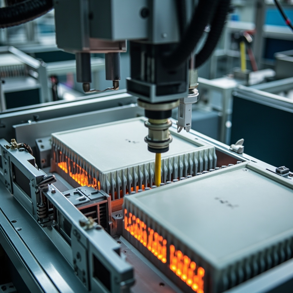
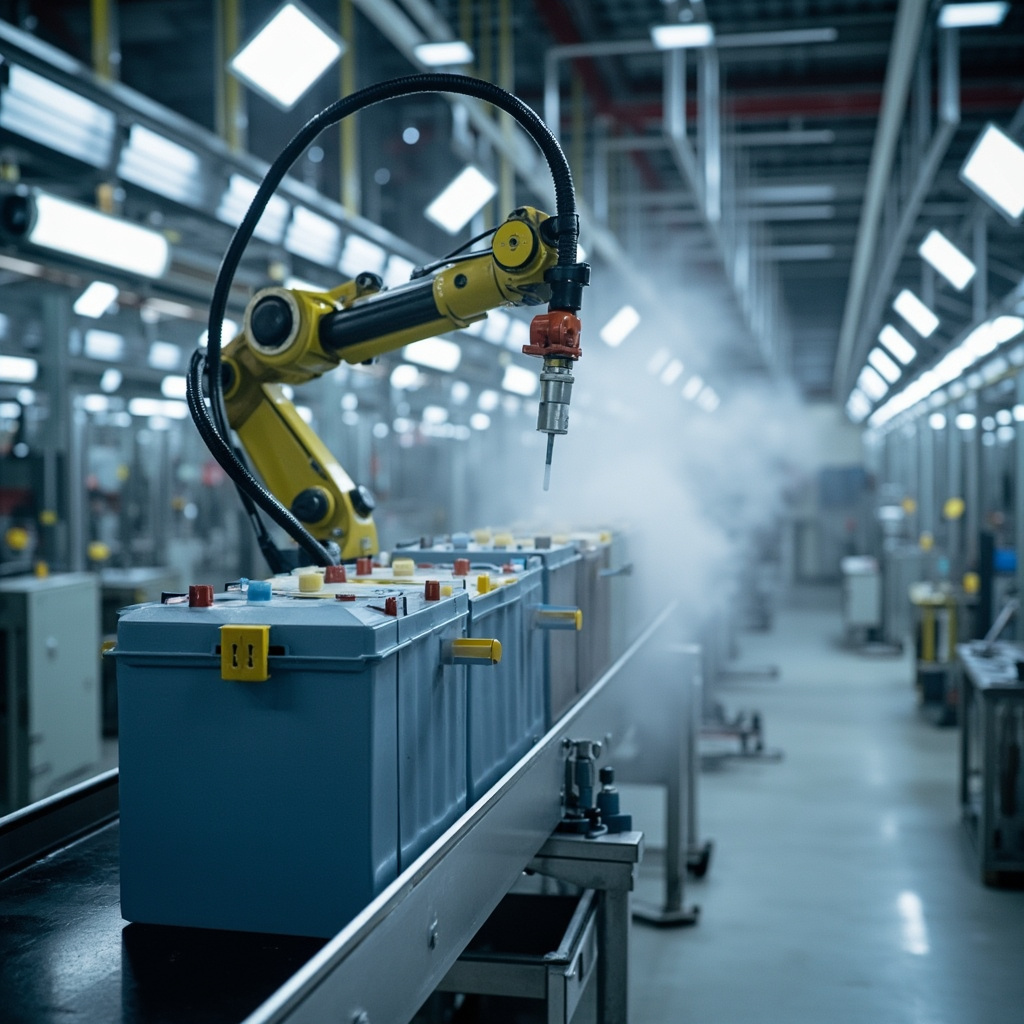
The battery pack enclosure is typically mounted underneath the vehicle chassis, directly exposed to extreme conditions such as impact from road gravel, immersion in muddy water, and corrosion from winter de-icing salts. A typical anti-corrosion coating system for the battery enclosure consists of:
- Pre-treatment: Silane treatment or zinc phosphating (coating weight 2-3 g/m²)
- Primer: Epoxy zinc-rich primer (dry film thickness 60-80 μm, zinc powder content ≥ 80%)
- Topcoat: Stone-chip resistant polyurethane or polyurea coating (dry film thickness 100-200 μm, elongation ≥ 150%)
The system must pass ≥ 1000 h neutral salt spray test (ASTM B117), and must simultaneously meet the stone chip resistance requirement (ISO 20567-1, -20°C low-temperature impact).
II. Insulation Coating for E-Drive Assembly
2.1 New Requirements of Flat-wire Motors for Insulating Varnish
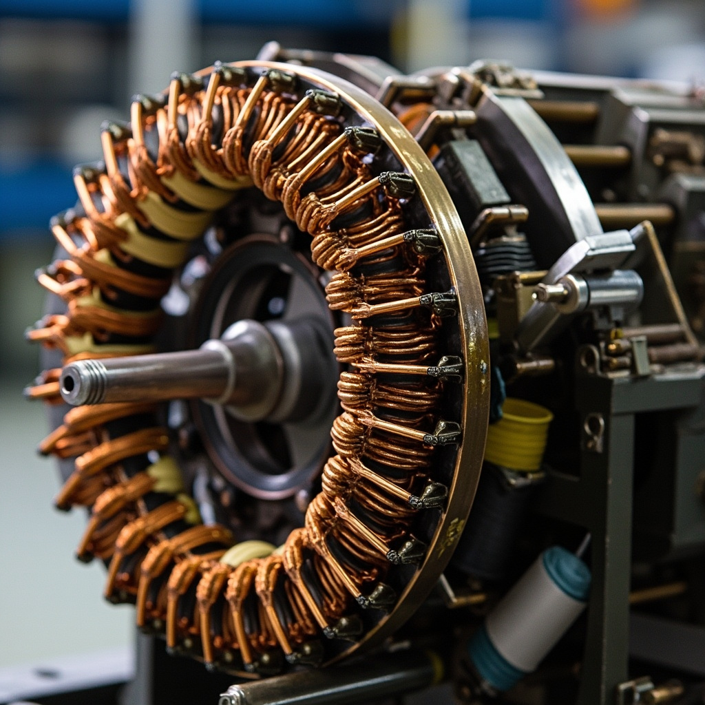
With the popularization of 800V high-voltage platforms, the operating voltage of drive motors has increased from the traditional 400V to 800V or even higher. Hair-pin motors have become the mainstream technical route due to their higher slot fill factor and power density. However, the rectangular conductors of hair-pin motors suffer from insulation layer stress concentration at the bends, which places extremely high demands on the flexibility and adhesion of the insulating varnish.
Key performance indicators of electrical drive insulation impregnating varnish include:
- PDIV (Partial Discharge Inception Voltage): ≥ 1500 Vp (800V platform recommended ≥ 1800 Vp)
- Corona resistance life: ≥ 500 h (IEC 60343, bipolar voltage 1.5 kV, frequency 10 kHz)
- ATF oil resistant: Immersed at 150°C × 1000 h, breakdown voltage retention rate ≥ 80%
- Heat class:Class H (180°C) or Class C (200°C+)
2.2 Comparison of insulating varnish impregnation systems
| Impregnating varnish type | Thermal class | PDIV (Vp) | ATF oil resistance | VOC content (g/L) | Curing condition |
|---|---|---|---|---|---|
| Epoxy-anhydride system | Class F (155°C) | 1200 – 1600 | Good | 50 – 150 | 150°C × 2h |
| Unsaturated polyesterimide | Class H (180°C) | 1500 – 2000 | Medium | 30 – 100 | 160°C × 1.5h |
| Silicone system | Class C (200°C+) | 1800 – 2500 | Excellent | 100 – 250 | 200°C × 2h |
| Water-based epoxy-polyurethane | Class F (155°C) | 1000 – 1400 | Fair | ≤ 50 | 140°C × 1h |
III. Protective Coatings for Electronic Control Systems
The PCB-level protection of electronic control units (OBC/DCDC/PDU) typically adopts conformal coating to prevent circuit failures caused by moisture, salt spray, and chemical gases. Additional requirements for conformal coating in new energy vehicle electronic controls include:
- Temperature resistance range: -40°C to 150°C (for installation near the engine compartment)
- CTI (Comparative Tracking Index): ≥ 600V
- Thermal conductivity: Some high-power-density OBCs require the coating to possess a certain level of thermal conductivity.
- UL 94 V-0 flame retardant rating
IV. Construction Process and Quality Control
4.1 Construction of Fireproof Coating for Battery Pack
The construction methods for battery pack fireproof coatings mainly include airless spraying and two-component precision dispensing. The dry film thickness of the fireproof coating is typically 1.0 – 3.0 mm, which is much higher than that of ordinary coatings, thus requiring special thick-film application processes. Key control parameters include:
- Gluing temperature: 25°C – 40°C (preheat before mixing two components)
- Application pressure: 15 – 25 MPa (airless spray)
- Film thickness uniformity: ±0.2 mm (online monitoring by laser thickness gauge)
- Curing conditions: 7 days at room temperature or accelerated curing at 80°C for 4 h
4.2 Electrical Drive Insulation Impregnation Process
The impregnation processes for flat wire motor stators mainly include dip, trickle, and vacuum pressure impregnation (VPI). VPI is the most reliable method to ensure high PDIV, as it removes air bubbles inside the winding through vacuum and then allows the insulating varnish to fully penetrate under pressure.
V. Industry Trends and Technology Outlook
Looking ahead to 2026–2030, coating technologies for the three electric systems (battery, motor, and electronic control) of new energy vehicles will develop in the following directions:
- Multifunctional integration: A single coating simultaneously achieves fire resistance + thermal conductivity + insulation, reducing process steps and material types
- CTP/CTC integrated adaptation:With the development of Cell-to-Pack and Cell-to-Chassis technologies, the coating needs to be directly compatible with the battery cells and vehicle body structural components
- Solid-state battery new requirement:Solid-state electrolytes are extremely sensitive to moisture and require encapsulation coatings with extremely high water vapor barrier properties
- Lightweight nanocoating: Using aerogel modification or hollow microsphere filling technology to reduce coating density by 30%-50%
- Self-healing smart coating: The coating can autonomously repair after damage, extending the battery pack's service life cycle.
FAQ: Common Issues with Coatings for the Three Electric Systems of New Energy Vehicles
Q1: How do the fireproof coating for battery packs and the passive fire suppression system work together?
The fireproof coating provides the first flame-retardant barrier, expanding to form a charred layer at the initial stage of thermal runaway. The passive fire suppression system (such as an aerosol extinguisher) acts as the second line of defense, activating when the temperature further rises to the trigger threshold. The two form a dual-protection architecture of "passive fire protection + active fire suppression."
Q2: How to select the PDIV standard for electric drive insulation impregnating varnish?
The PDIV value should be at least 1.5 times the peak operating voltage of the motor. For a 400V platform, PDIV ≥ 900 Vp; for an 800V platform, PDIV ≥ 1500 Vp (recommended ≥ 1800 Vp to reserve a safety margin).
Q3: What are the differences in application processes between thermal conductive structural adhesive and thermal conductive gap-filling adhesive?
Thermal conductive structural adhesive requires precise control of the dispensing path and adhesive amount (servo metering valves are commonly used), because it also serves a structural bonding function; thermal conductive gap-filling adhesive is mainly used to fill large gaps, has relatively lower requirements for dispensing accuracy, but requires compressive resilience.
Q4: What is the relationship between the inter-cell thermal insulation coating and the module-level fireproof board?
The inter-cell thermal insulation coating (such as aerogel coating or mica paper) is used to delay the propagation of a single cell's thermal runaway to adjacent cells; the module-level fireproof board (such as mica board) provides a higher level of fire isolation at the module level. The two are functionally complementary and together form a multi-level thermal propagation protection system.
Q5: How to solve the adhesion problem of magnesium alloy substrate for battery enclosures?
A loose magnesium oxide layer forms very easily on the surface of magnesium alloy, leading to poor coating adhesion. Solutions include: micro-arc oxidation (MAO) pretreatment to form a dense ceramic layer, treatment with dedicated silane coupling agents (containing Zr/Ti systems), or the use of epoxy primer containing special adhesion promoters.
Q6: What are the requirements for the ATF oil resistance of insulating varnish in an oil-cooled electric drive environment?
The insulating varnish for oil-cooled electric drives must pass the ATF oil immersion aging test: after immersion in ATF oil at 150°C for 1000 h, the breakdown voltage retention rate must be ≥ 80%, and the varnish film must not show blistering, softening, or peeling. The silicone system performs best in this test.
Q7: What new challenges does the 800V high-voltage platform pose to insulation coatings?
The challenges of the 800V platform include: higher PDIV requirements (≥ 1500 Vp vs 900 Vp for 400V platforms), stronger partial discharge erosion effects, more stringent requirements on the dielectric constant and dissipation factor of insulation varnish, and higher du/dt stress brought by high-frequency switching (SiC devices).
Q8: How can the battery pack coating pass the GB 38031-2020 thermal propagation test?
GB 38031-2020 requires that the battery pack shall not catch fire or explode within 5 minutes after thermal runaway is triggered in a single cell. The coating strategies include: applying ≥ 2mm intumescent fireproof coating on the inner surface of the battery pack upper cover, filling thermal insulation potting adhesive between cells, and laying a thermal conductive + insulating composite coating at the bottom of the module.
Q9: How can low-density thermal insulation coatings achieve weight reduction goals?
By introducing lightweight fillers such as hollow ceramic microspheres (density 0.2-0.6 g/cm³), aerogel powders (density 0.1-0.3 g/cm³), or foamed microcapsules, the density of fireproof coatings can be reduced from 1.3-1.5 g/cm³ to 0.6-0.9 g/cm³. However, it should be noted that low density may affect the strength of the charred layer, requiring a balance through formulation optimization.
Q10: How does the painting line accommodate both traditional body paint and specialized three-electric coatings?
Battery packs and e-drive assemblies are typically not painted on the body painting line, but are finished on independent dedicated painting lines. The curing temperature of three-electric coatings is usually lower than that of traditional body paint (electrophoresis 180-200°C vs. three-electric coatings commonly 80-150°C), so co-line production is not feasible. Some newly built plants adopt a "main line + auxiliary line" parallel layout to improve efficiency.
Q11: How to test and evaluate the expansion ratio of the charred layer of fireproof coatings?
Refer to the expansion ratio test method in GB 14907-2018 "Fire-resistant Coating for Steel Structure". Heat the coating samples in a muffle furnace at different temperatures (300°C, 500°C, 800°C), and measure the ratio of the charred layer thickness to the original thickness. Generally, the expansion ratio is required to be ≥ 20 times, and the charred layer structure should be dense, uniform, and free of penetrating cracks.
Q12: What are the environmental regulatory compliance requirements for coatings used on battery packs?
It is necessary to meet the restrictions on VOCs, heavy metals (Pb, Cr6+, Hg, Cd), benzene series, and glycol ethers specified in GB 24409-2020 "Limit of Harmful Substances in Coatings for Vehicles". Battery packs for export also need to comply with the restrictions on Substances of Very High Concern (SVHC) under the EU ELV Directive (2000/53/EC) and the REACH Regulation.
Related Reading
Summary
The protective coating for the three-electric system of new energy vehicles is a highly interdisciplinary technical field, involving fireproof material science, electrical insulation engineering, thermal management design, and corrosion protection technology as four major professional directions. When selecting a coating solution, it is necessary to start from the overall vehicle safety objectives, and combine the battery pack structural design, the voltage level of the electric drive platform, and manufacturing cost constraints to conduct systematic solution selection and process planning. Kexin New Materials Coating Factory has provided customized three-electric system protective coating solutions for multiple new energy vehicle enterprises, and welcomes you to contact us for professional technical consultation.