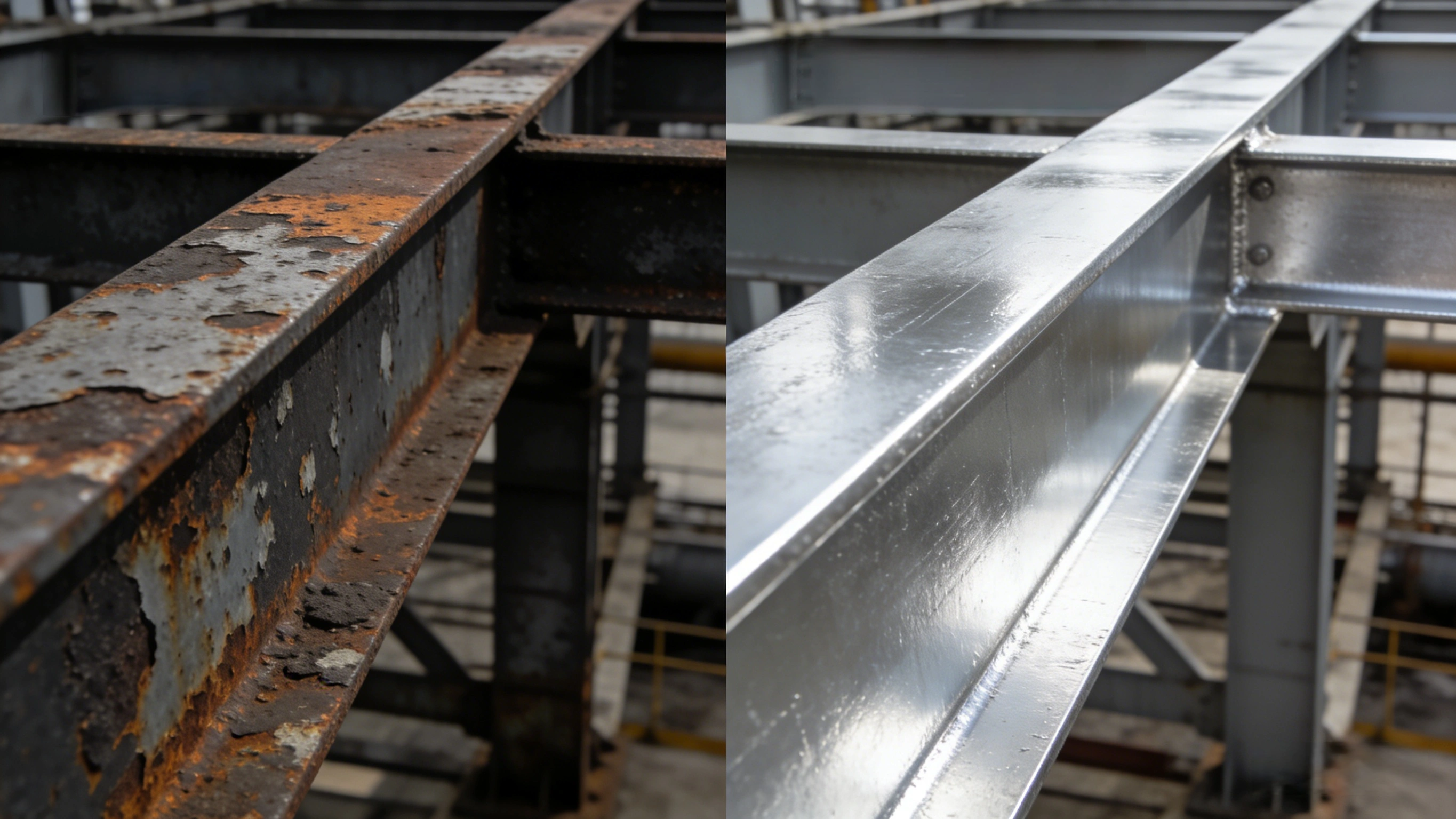
Corner weld and edge corrosion of storage tanks is the local rusting and coating failure that appears ahead of flat areas at geometric discontinuities on vertical cylindrical welded steel tanks - fillet welds and weld toes, the annular fillet weld at the bottom annular plate, nozzle and reinforcing pad roots, sheared and thermally cut plate edges - where insufficient dry film thickness, discontinuous surface profile, uncorrected weld defects and holiday-detection blind spots combine. It is not the name of a corrosion mechanism but an umbrella term for a set of measurable subjects: preparation level judged to ISO 8501-3, weld geometry to ISO 5817, film thickness to ISO 19840 or SSPC-PA 2, coating continuity by spark holiday testing to ASTM D5162 and similar, and environmental severity classified per ISO 12944-2.
The familiar picture in a coastal tank farm: in years 3 to 5 of service, the paint on the broad shell courses is still sound with only a slight loss of gloss, yet 1 mm to 3 mm rust streaks run from the underside of the corner welds, the bottom annular plate and its annular fillet weld show blistering and peeling paint, and manway and nozzle roots carry a full ring of rust. By the time the insulation comes off for inspection, the wall beneath the circumferential weld has already thinned locally. The owner's puzzle is one sentence: the dry film thickness acceptance report passed, so why did these spots fail first. The answer lies in measurement layout and acceptance criteria - routine gauge points sit on flat areas, and corner welds and edges receive neither the same sampling nor the same judgement.
TL;DR: the conclusions first
- Welds and edges are subjects in their own right: ISO 8501-3:2025 sets separate requirements in three preparation levels P1, P2 and P3; heavy-duty systems typically start from P2, and P3 applies above C4 or where high durability is targeted.
- Edge rounding is quantifiable: P3 requires a rounding radius not less than 2 mm on machined-cut edges, and thermal-cut edges are commonly treated with 3 chamfering or 3 grinding passes; below 3 mm plate thickness P3 is often unachievable, so design and shop practice must compromise.
- Undercut limits scale with thickness: ISO 5817:2023 continuous undercut at level B is 0.05t and no more than 0.5 mm, level C is 0.1t, level D is 0.2t; under the GB 50205-2020 system Grade 2 welds stay within 0.05t and 0.5 mm with continuous length up to 100 mm.
- DFT passing does not mean corner welds pass: ISO 19840 requires the mean no lower than nominal, no single reading below 80% of nominal, and readings below nominal no more than 20% of the set; the IMO PSPC applies the 90/10 rule, and Chinese project practice likewise judges thin weld stripes and nodal areas against 90/10.
- Test voltage follows film thickness: ASTM D5162 treats 0.5 mm (20 mil) as the common dividing line between low-voltage wet sponge and high-voltage spark; high voltage per V = M × √T with M of 3294 or 7843, 1.5 mm corresponding to about 9.6 kV, and low voltage commonly 5 V to 90 V.
- Roughness and salts are the weld zone's hidden traps: coatings are specified in Rz, not Ra - on the same surface Rz is about 4 to 6 times Ra; most systems need Rz 40 µm to 75 µm, PSPC 30 µm to 75 µm, thermal-sprayed aluminium needs Sa 3 with Rz not less than 75 µm, and soluble salts stay within 50 mg/m² as NaCl equivalent.
- Stripe coating puts thickness back at geometrically unfavourable locations: ISO 12944-5 defines the stripe coat as the extra coat applied specifically to add thickness at edges, welds and threaded parts, so the clause must list locations, material, passes and gauge points.
- Service conditions must be assessed separately: tank linings are outside the scope of GB/T 30790 and ISO 12944; for corrosion under insulation, NACE SP0198 points to a metal surface temperature window of roughly -4 °C to 175 °C, and shutdown condensation pushes risk across the boundaries.
Why tank coatings fail first at corner welds and edges
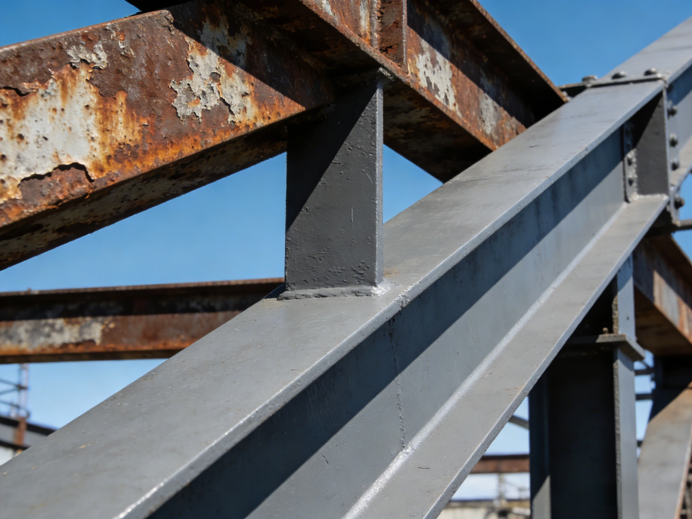
Corner welds and edges are not a single-variable problem; three things happen at once: the coating forms an uneven film-thickness profile at geometric discontinuities, blast media cannot treat weld metal and base metal to the same grade, and the geometry itself holds water and product down at the weld root. Where circumferential and longitudinal welds cross on a tank, the joint is T-shaped or K-shaped; between weld toe and base metal there is a step rather than a ramp, and the vertical face of that step is limited by line of sight and gun angle during spraying, so its actual transfer efficiency runs below that of flat areas. For medium and system selection on tank interiors, see Storage tank internal anticorrosion coating systems and medium selection; this article covers only the open line of shell exteriors, annular plates and weld geometry.
Geometry, film thickness and trapped medium act together
Protruding edges thin out through gravity levelling and surface-tension pull-back, so the dry film on a sharp right-angle arris is often clearly below the flat readings taken from the same pass; re-entrant corners and weld toe roots are the opposite, where pooled liquid and settled dust leave a coating that is thick but porous, with concentrated drying-shrinkage stress, so pinholes and micro-cracks appear readily. The steps formed by excess weld metal and undercut break the continuity of the anchor profile across the weld zone: abrasive rebounds off the hardened heat-affected zone and cannot bite deep into the root or the undercut groove, so the weak link in adhesion shows up here first, not on the broad flats.
Three location classes - do not mix them in one table
On the same tank there are at least 3 classes of location that must be judged separately: the external atmospheric side (system and maintenance intervals chosen per ISO 12944-2), the internal product side (different codes govern linings and coatings, and the scope of GB/T 30790 and the ISO 12944 series explicitly excludes tank linings), and the under-insulation and buried side (governed by condensation and soil exposure, assessed to standards such as NACE SP0198). Writing them into one acceptance table produces clauses that look strict but cannot be executed.
| Location | Geometric feature | Coating weak point | Early failure sign | Primary countermeasure |
|---|---|---|---|---|
| Corner welds and weld toes | T-shaped or K-shaped step; the weld toe is a vertical face | Low transfer efficiency, discontinuous anchor profile | Rust streaks 1 mm to 3 mm under the weld toe | Blend-grind the toe, re-verify at P2 or P3, and apply the stripe coat first |
| Bottom annular plate annular fillet weld | Horizontal-to-vertical junction, in ground contact outside | Trapped liquid; coating permanently damp | Lifted annular plate, water ingress and rust run-out | Re-make the water apron and feathered overlap; dedicated gauge points for this location |
| Sheared edges and arrises | Sharp right-angle corners, burrs | Gravity drain-back thins the film well below flats | A rust line along the edge spreading to both faces | Rounding radius not less than 2 mm, or 3 grinding passes |
| Thermally cut edges and bevels | Scale and hardened band side by side | Shallow profile; abrasive rebounds off hard surfaces | Blistering and local peeling on the cut face | Second blast or grind the cut face; power-tool to St 3 where needed |
| Nozzle and reinforcing pad roots | Multiple welds converging, narrow gaps | Residual grit and slag hard to clear | A ring of rust at the root, dense pinhole alarms | Clean first, then holiday test; grind repairs 50 mm beyond the holiday and retest |
Preparation grades and weld geometry: measurable criteria from drawing to acceptance
ISO 8501-3 is the standard that grades welds and edges in their own right. The current edition, ISO 8501-3:2025, was published in August 2025 and replaces the 2007 edition; the corresponding Chinese text is GB/T 8923.3-2009 (identically adopting ISO 8501-3:2006, so it trails the 2025 edition). The standard describes how far welds, edges and other defect areas must be dressed in three preparation levels, P1, P2 and P3: P1 only requires removal of loose spatter and slag and allows an intermittent weld; P2 requires a continuous weld, sharp edges and open porosity removed, and loose and lightly adhering spatter gone; P3 requires defects essentially invisible, the weld blending smoothly into the base metal, and a rounding radius on machined-cut edges not less than 2 mm. Which level applies follows from the ISO 12944-2 corrosivity category and the target durability, not from what is convenient on site.
| Preparation level | Weld requirement | Machined-cut edge | Thermally cut edge and bevel | Link to ISO 5817 and typical use |
|---|---|---|---|---|
| P1 light | Remove loose slag and spatter; intermittent welds allowed | Simple deburring | No mandatory bevel dressing | Close to level D; low-corrosivity environments or short-term protection |
| P2 moderate | Continuous weld; sharp edges and open porosity removed; lightly adhering spatter gone | About 1 mm chamfer per side | Thermally cut faces need secondary cleaning | Level C is the common starting point; the workhorse requirement for marine and industrial environments, and PSPC calls for P2 |
| P3 thorough | Defects essentially invisible; weld blends smoothly into base metal | Rounding radius not less than 2 mm | 3 chamfering or equivalent grinding passes; difficult below 3 mm plate thickness | Paired with level B; chosen above C4, for high durability, or with thermal-spray systems |
Undercut, excess weld metal and misalignment: 3 geometric quantities that decide coating thickness
Coatings depend on weld geometry because all three features directly consume film thickness: undercut is itself a groove whose depth can reach a fraction of the base metal thickness several times over, and it must be filled with coating before protection can even be claimed; excessive reinforcement forms a step whose crest is never properly reached; misalignment opens gaps in the overlap zone. ISO 5817:2023 sets three levels for continuous undercut: level B up to 0.05t and no more than 0.5 mm, level C up to 0.1t, level D up to 0.2t; cracks and lack of fusion are not permitted at any level. The Chinese steel-structure acceptance system (GB 50205-2020, GB 50661-2011) phrases the limits by weld class: Grade 1 welds allow no undercut, Grade 2 stays within 0.05t and 0.5 mm with continuous length no greater than 100 mm, Grade 3 within 0.1t and 1.0 mm. Repair grinding at one location should not exceed 2 attempts, because repeated heat input hardens the heat-affected zone and further degrades the anchor profile.
- Set the grade at design stage: put P1/P2/P3 into the drawings and welding procedure documents, not into a verbal request before painting.
- Hold point before weld approval: defects show in the as-welded condition and again after cleaning, and must be re-checked once after blasting.
- Dressing must not impair weld integrity: ground welds must still meet the profile and tolerances set by the welding quality manager or the design.
- No more than 2 repair attempts at one location: beyond that, a dedicated procedure confirmed by the designer is required, with the heat-affected zone condition recorded.
Film thickness: why corner welds and edges run systematically thin
DFT passing on flat areas does not mean corner welds pass, for two reasons. One is film formation itself: coating drains back and thins at sharp arrises and piles up in re-entrant corners with gas pores inside. The other is measurement: a blasted profile biases magnetic gauges, and specifications normally require deducting a surface-profile correction - commonly 10 µm to 25 µm in published sources - while gauge points spread evenly by area across flats keep corner welds and edges out of the statistics altogether. How film thickness and waste factors are calculated is covered in Dry film thickness, theoretical spreading rate and waste factor calculations; what must be added here is gauge-point layout by location class.
Thinning on protruding edges, build-up in re-entrant corners
In a specification, split this into two sentences: first the nominal dry film thickness of each coat and the total system thickness; then the number of gauge points and the acceptance rules for the three trouble locations - corner welds, edges and nozzle roots. Without the second sentence, the site will close out the job on flattering flat-area numbers.

How the 4 DFT acceptance rules differ
| Rule | What is judged | Gauge point structure | What it means for edges and welds |
|---|---|---|---|
| ISO 19840 | Mean no lower than the nominal DFT; no single reading below 80% of nominal; readings between 80% and 100% no more than 20% of the set; upper limit not exceeded | All readings grouped and counted by inspected area | Any corner or edge reading below 80% triggers local rework; no flattering mean can substitute |
| SSPC-PA 2 | Layered counting with the surface probe method; single points commonly judged within an 80% to 120% band of the specified value | The mean of 3 readings at one spot forms a single gauge point; several gauge points represent an area | It is about how points are counted; without named locations, thin corner welds stay invisible |
| IMO PSPC 90/10 | 90% of readings at or above nominal, the remainder no lower than 90% of nominal | Statistics over the full compartment or tank area | Tougher on corners: corrosion at edges and welds must affect less than 20% of the area of those locations |
| Chinese project practice | Published common rule: 90% of points at design thickness, the remaining 10% no lower than 90% of design, with thin weld stripes and under-coated joints failing acceptance | Inspection lots by member and location | Separating welds and nodal points is what makes rejection enforceable; it only works when written into the specification |
Stripe coat: method, benefits, and how to write it into a specification
ISO 12944-5 names every coat in a system: the primer is coat 1, any coat between primer and topcoat is an intermediate coat, a tie coat improves intercoat bonding or eliminates void defects, and a stripe coat is an extra coat applied specifically to add thickness at weak locations such as edges, welds and threaded fittings. The significance of stripe coating is that it is the one means of deliberately putting film thickness back at geometrically unfavourable locations - something broad-area spraying cannot do without causing sagging.
- Choose the right material: use solvent-free or high-solids brushable stripe paints, and avoid pinholes caused by thick applications of high-volatility products.
- Stripe before broad spraying: brush 2 passes in crossing directions to wet the weld toes and edges, then move on to spray application.
- Log the wet film: read a wet film comb during striping - easier proof of compliance than magnetic DFT afterwards.
- State the ceilings: limit wet film thickness per pass and total thickness to prevent sagging, exotherm cracking and loss of intercoat adhesion.
- List the locations: circumferential-longitudinal weld crossings, nozzle roots, bottom annular plates, sheared and thermally cut edges - every item checkable.
Benefits and risks must be written together. The benefits: verifiable film thickness and far less rework in the weld zone. The risks: sagging, cure exotherm in thick applications, solvent entrapment and reduced intercoat adhesion, especially with high-build solvent-free products. So the clause must also state ceilings: the wet film thickness of a single stripe pass, the number of passes allowed, a hard cap such as total thickness no more than 60 µm above the system's nominal value, and a requirement to record over-thick areas. Stripe coating becomes an acceptable item only when the location list, material, passes and gauge points are written down; a bare line about reinforcing edges and corners will be treated as optional and cut.
Roughness and soluble salts: two hidden traps at welds and heat-affected zones
Roughness and salts are the two invisible tracks on which weld zones run out of control, and the parameter must be fixed first: coating standards use Rz (the peak-to-valley anchor profile height), not the Ra of machining practice, and Rz cannot be substituted - on the same blasted surface Rz is roughly 4 to 6 times Ra. Common reference points: most systems require Rz 40 µm to 75 µm; the IMO PSPC specifies a profile of 30 µm to 75 µm after blast cleaning; thermal-sprayed aluminium (TSA) requires Sa 3 with Rz not less than 75 µm; the ISO 8503-1 comparator specimens have nominal values of 25 µm, 60 µm, 100 µm and 150 µm for grit (G) and 25 µm, 40 µm, 70 µm and 100 µm for shot (S), while GB/T 13288 grades surface roughness as fine, medium and coarse. Soluble salts are converted to sodium chloride equivalent per ISO 8502-9, and the PSPC limit is 50 mg/m².
- Specify Rz, not Ra: Rz is the mean peak-to-valley depth and correlates directly with adhesion; Rz runs about 4 to 6 times Ra, and the two cannot be converted into each other for acceptance.
- Do not mix comparator sets: grit (G) and shot (S) differ in morphology, and the ISO 8503-1 nominal values are 25 µm, 60 µm, 100 µm, 150 µm and 25 µm, 40 µm, 70 µm, 100 µm respectively.
- Keep tape evidence: replicate tape readings (ISO 8503-5, ASTM D4417 method C) minus the 50 µm backing, averaging 2 to 3 gauges per area, leave a paper record.
- Gauge corners separately: blasting near corners and welds tends shallow, so the sampling plan must count them apart from flats.
Why the weld zone is easy to under-blast
Four physical reasons make the weld zone easy to under-blast: abrasive forms an effective anchor profile only at incidence of roughly 45° to 90°, and the weld toe groove face and root point away from the gun; weld metal and heat-affected zone are harder than the base metal, so rebound shallows the indentations; slag is embedded in undercut grooves and pores, which no amount of blasting will clean until they are dressed; and secondary damage (weld fixturing, flame straightening) regularly lands on already-prepared areas. The countermeasure is to make the preparation grade a hold point before weld approval, re-inspect once after blasting, and where necessary touch up by local grinding or power tooling to St 3. Requiring a dust rating of grade 1 per ISO 8502-3 follows the same logic: residual grit and dust around welds are harder to clear than on flats.
Holiday detection: voltage selection, method limits and missed defects at welds
Film thickness sets the boundary between holiday-detection methods. ASTM D5162 provides that the low-voltage wet sponge method is generally used for total thickness up to 0.5 mm (20 mil) and the high-voltage spark method above 0.5 mm; high voltage may also be used between 0.25 mm and 0.5 mm, but the voltage must be correctly calculated and set and accepted by the coating manufacturer. The common high-voltage formula is V = M × √T (T the dry film thickness in mm), with the annex taking M = 3294 up to 1 mm and M = 7843 above 1 mm - 1.5 mm works out to about 9.6 kV; low-voltage wet sponge typically runs 5 V to 90 V. The allowable number of holidays must be agreed before the test, because the criterion depends on thickness, design and service conditions. For how DFT and pinhole testing are combined in tank acceptance inspection, see Coating project acceptance: ISO 12944 and SSPC-PA 2 film thickness and pinhole testing.
| Method | Applicable total DFT | Voltage or probe | Weld-zone and field-repair considerations | Judgement basis |
|---|---|---|---|---|
| Low-voltage wet sponge (ASTM D5162 method A) | Generally up to 0.5 mm | Commonly 5 V to 90 V | Safe on in-service and wetted coatings; suits operating tanks and thin films | Every alarm is a holiday; the allowable count must be agreed beforehand |
| High-voltage spark (method B) | Mainly above 0.5 mm | Equipment range about 2.3 kV to 30 kV; V = M × √T with M = 3294 or 7843 | In the 0.25 mm to 0.5 mm band, use requires calculation and manufacturer consent; risk of puncturing sound older coating | Locate, mark, repair and retest every holiday |
| Field repairs and vacuum method | Heavy linings or geometry-restricted areas | Copper or carbon brush probes, vacuum testing box | Keep probe travel at about 0.3 m/s or less; the ground connection must be reliable | 100% testing of repair areas, with the holiday log closed out |
4 reasons holiday miss rates run high in the weld zone
High holiday miss rates in the weld zone are a geometry and electrical problem, not an instrument problem: the probe-to-steel distance varies across the weld toe, so the breakdown voltage is effectively raised over crowns and defects in depressions are missed; sensitivity drops when the ground return is poor, so connection points on the tank grounding grid must be confirmed deliberately; porous weld surfaces and residual slag generate continuous false alarms; and putting high voltage straight onto a coating already in service risks puncturing sound areas - D5162 warns explicitly, and linings that have been immersed or wetted out deserve particular care. Site practice also keeps probe travel at about 0.3 m/s or less, tests 100% of repair and field-joint areas, and prefers low-voltage wet sponge or vacuum boxes on operating tanks.

Closing the loop on repair and retest
Retesting must close the loop: mark each holiday at least 50 mm outside its edge, grind out into sound coating to form a feathered overlap, recoat per the system to the original design thickness, then retest at the same voltage; published sources also carry a common requirement to build the repaired area up to 120% of the original coating thickness before re-inspection. Whether adhesion suffered is checked by pull-off testing, one comparison set in the repair area and one in the parent area - criteria and failure modes in Adhesion acceptance for anticorrosion coatings: pull-off test criteria and failure modes. The holiday log must carry location, date, voltage, count and who closed it out, so the second turnaround can tell a construction defect from in-service degradation.
Internal product, external atmosphere and under insulation: 3 service conditions, assessed separately
The 3 service conditions have different drivers and their criteria cannot be borrowed across. The internal product side is about immersion, temperature cycling and wet-dry alternation at the liquid-vapour line; blistering and swelling cluster in the liquid-trap areas of the bottom shell course and at nozzle roots, and this side belongs to lining and food-contact rulesets - where migration and cleanliness requirements apply, see Food-grade storage tank lining coatings and migration compliance. On the external atmospheric side, systems are selected from the ISO 12944-2 classification; published first-year thickness loss for low-carbon steel is about 25 µm to 50 µm in C3, about 50 µm to 80 µm in C4 and about 80 µm to 200 µm in C5, and the example systems in GB/T 30790.5 carry total nominal DFT of about 280 µm for high-durability C4, about 240 µm with a zinc-rich primer, and about 320 µm for C5 targeting 15 years or more, with zinc dust at no less than 80% of the non-volatile matter of the zinc-rich primer. The underside of tank bottoms and buried parts commonly share service with cathodic protection, so the coating must be selected for cathodic disbondment resistance - see Cathodic disbondment of coatings: mechanism, test standards and cathodic protection design.
| Service condition | Governing basis | Failure mechanism | Coating key points |
|---|---|---|---|
| Internal product side | Lining and food-contact rulesets (GB/T 30790 and ISO 12944 do not cover tank linings) | Immersion, swelling, wet-dry alternation at the liquid-vapour interface | Select the system for the product; judge blistered and swollen areas separately |
| External atmospheric side | ISO 12944-2 classification and the GB/T 30790.5 example systems | Salt deposition combined with condensation and UV chalking | About 280 µm total DFT for C4, about 240 µm with a zinc-rich primer, about 320 µm for C5; stripe coating puts thickness back on corners and edges |
| Under insulation and buried side | NACE SP0198, ISO 19277, HG/T 5178-2017 | Water ingress and condensation cycling within roughly -4 °C to 175 °C | Stripe coat or thermal-sprayed metal first at cladding terminations and penetrations; insulation never replaces the anticorrosion coating |
Corrosion under insulation is the class of edge failures on tanks and pipe racks most easily overlooked: published statements of NACE SP0198 indicate that on carbon steel with metal surface temperature in the range of roughly -4 °C to 175 °C, once water enters the insulation and the surface cycles wet and dry, the corrosion rate is markedly higher than in the dry state; below that window moisture freezes and above it surfaces tend to dry out, so risk falls - but condensation during shutdown cooling drags the real risk across the window boundaries. Domestically, HG/T 5178-2017 gives system direction by temperature range, and the testing and evaluation framework follows ISO 19277:2018. Two practical consequences for the coating system: edges at cladding terminations, laps and pipe penetrations must first receive a stripe coat or thermal-sprayed metal, and an insulating coating is no substitute for the anticorrosion coating. For thermal-sprayed zinc-aluminium with sealers, see Thermal-sprayed zinc-aluminium coating process and system design; for quantified design life and maintenance intervals in high-salinity marine service, see Design life and maintenance intervals for CX high-salinity marine steel structures.
Key figures at a glance (with units)
- Rounding radius, machined-cut edges: not less than 2 mm (the P3 requirement of ISO 8501-3:2025).
- Depth cap, continuous undercut: 0.05t and no more than 0.5 mm (level B of ISO 5817:2023).
- Single-point floor for DFT: no reading below 80% of the nominal dry film thickness (ISO 19840); 90% of readings at or above nominal and the remainder no lower than 90% of nominal (the PSPC 90/10 rule).
- Holiday-detection dividing thickness: 0.5 mm, i.e. 20 mil (ASTM D5162).
- High-voltage formula: V = M × √T with M = 3294 (T up to 1 mm) or 7843 (T above 1 mm), T in mm; 1.5 mm gives about 9.6 kV.
- Common blast anchor profile range: Rz 40 µm to 75 µm; PSPC 30 µm to 75 µm; thermal-sprayed aluminium Sa 3 with Rz not less than 75 µm.
- Soluble salt limit: no more than 50 mg/m² expressed as NaCl equivalent (conversion per ISO 8502-9).
- Priming window after blast cleaning: published sources put priming within 4 h to 6 h; beyond that, flash rust means re-preparation.
- Example C4 system: total nominal DFT about 280 µm, about 240 µm with a zinc-rich primer; about 320 µm for C5 targeting 15 years or more (GB/T 30790.5 examples).
- One criterion of a sound coating bears directly on edges: IMO PSPC allows rust spotting over less than 3% of the area, but corrosion at edges and welds must affect less than 20% of those locations.
Acceptance records and traceability
Whether the acceptance documents are traceable decides who carries the rework cost three years on. An executable record set covers at least the items below, and every one of them must be filled in with measured values rather than a mark that the work was done.
- Measured record of weld and edge preparation: location number, dressing method, achieved P level and inspector.
- Stripe coat records: material name and batch number, number of passes, wet film readings, application time, ambient temperature and humidity, and dew point margin.
- Profile and salt measurements: method (comparator, tape or stylus instrument), Rz range, salt content in mg/m² and sampled area.
- DFT statistics by location: mean, single-point floor and compliance rate for each group - flats, corner welds, edges, nozzle roots.
- Holiday log: voltage, probe type, travel speed, number and location of holidays, repair and retest results.
- Adhesion and appearance re-verification: pull-off values with failure mode, and degradation rated per the ISO 4628 series.

High-risk location checklist
- Bottom annular plate and annular fillet weld: capillary rise from outside and ponding at the water apron - where rust origins concentrate.
- Lower 500 mm or so of the bottom shell course and the foundation ring beam: wet-dry alternation combined with mechanical impact.
- Nozzle, reinforcing pad and manway roots: unfavourable weld geometry plus frequent secondary heat damage; thin coating and trapped grit.
- Roof wind girder, handrails and grab-bar weld points: easily trampled during high-level maintenance, and they hold water.
- Insulation terminations, cladding laps and pipe penetrations: the main ingress paths for water and condensation - CUI hot spots.
- Circumferential-longitudinal weld crossings: the T-shaped or K-shaped geometry defeats both spray gun and probe, so holiday miss rates run high.
- Floating roof gauging ladder, guide posts and heating coils: abrasion combined with product hold-up; verify local thinning by wall thickness measurement.
Frequently asked questions
Must corner welds be ground flush with the base metal?
Not necessarily - it depends on the preparation level and corrosivity category selected. P2 only requires a continuous weld with sharp edges and open porosity removed, and does not ask for the reinforcement to be ground flat; smooth blending and essentially invisible defects belong to P3. The test is whether the coating can form a continuous film at nominal thickness over the weld toe, not whether the weld looks flush. In practice, a dressing check is made after weld approval but before blasting, followed by one re-inspection after blasting, with the weld, the toe and the surrounding 50 mm recorded as a single acceptance unit.
Why does the same set of gauge points pass under SSPC-PA 2 but fail under ISO 19840?
The two rules have different statistical structures. ISO 19840 constrains the mean, the single-point floor and the share of readings below nominal all at once, and any one reading below 80% of nominal triggers local rework; SSPC-PA 2 counts by layer with the surface probe method and judges on the relationship between gauge points and areas, commonly applying an 80% to 120% band. If the contract names only one rule - or blends both - the contractor and the owner will each walk away with a passing conclusion. The fix is to designate 1 of the two in the technical specification and state the number of gauge points for every location class.
Is a higher holiday test voltage simply safer?
No. Below the breakdown threshold, pinholes go undetected; above it, sound coating is punctured, creating new defects exactly at welds and edges where the film is already thin. ASTM D5162 requires the voltage to be set first from total DFT and the dielectric strength of the coating, with the annex formula V = M × √T taking M = 3294 up to 1 mm and 7843 above 1 mm, and high voltage in the 0.25 mm to 0.5 mm band needing the coating manufacturer's acceptance. The allowable holiday count must also be agreed before testing, otherwise the results cannot support an acceptance decision.
Can coatings on tanks in service be re-tested directly with high-voltage spark?
Care is required. D5162 warns explicitly that high-voltage testing of coatings that have been immersed or wet out for long often misjudges through conducted moisture and surface contamination, and can puncture areas that were sound. Routine practice on operating tanks prefers low-voltage wet sponge or vacuum boxes, combined with ultrasonic wall thickness measurements to verify thinning; where high voltage is genuinely needed, limit the zone, reduce the voltage and log every pass, so sound areas are not turned into new holidays.
Does a zinc-rich primer at corner welds need a sealer or tie coat?
It depends on the system and the coats that follow. Zinc salts form on epoxy zinc-rich surfaces after prolonged post-blast exposure, and zinc segregation on rough profiles makes conductive paths uneven across weld zones, so many systems add an epoxy sealer or tie coat over the zinc-rich primer to stabilise the interface before the intermediate coat. Per GB/T 30790.5 and ISO 12944-5, zinc dust must be no less than 80% of the non-volatile matter of a zinc-rich primer, and thickness and system are set together from the corrosivity category and durability class; corner welds and edges still rely on stripe coating to recover thickness, and a sealer cannot replace that step.
Where does the treatment of thermally cut edges differ from machined sheared edges?
Sheared edges mainly carry burrs and sharp right-angle corners, dealt with by chamfering or rounding - P3 requires a radius not less than 2 mm. Thermally cut edges arrive with scale, a hardened layer and adherent slag; abrasive rebounds off the hardened surface and the indentations come out shallow, so a secondary cleaning or grinding is needed before the profile is verified. The acceptance parameters differ as well: the geometric radius on one hand, anchor profile Rz and blast cleaning grade met together on the other - writing one clause that edges are 'acceptably prepared' hides the difference.
Can corrosion under insulation be solved by applying more film thickness?
No. CUI is driven by repeated wet-dry cycling once water enters the insulation, plus shutdown condensation; extra thickness only delays things and cannot block water and chloride from reaching the metal. The effective sequence is to seal first - cladding terminations, laps and penetrations - and then select the system by temperature window from epoxy-phenolic, modified silicone or thermal-sprayed aluminium, the last requiring Sa 3 and Rz not less than 75 µm as pretreatment. Thermal insulation and corrosion protection are two jobs; conflating them spoils both.
Can internal tank linings be accepted under ISO 12944 or GB/T 30790?
Not directly. The GB/T 30790 and ISO 12944 series address protective coating systems on steel surfaces in atmospheric environments, and their scope excludes thick-film materials above 2 mm DFT and storage tank linings. The interior belongs to immersion and medium-compatibility rules: liquid resistance and diffusion testing for the specific product, migration assessment against food-contact requirements where applicable, and holiday detection and thickness measurement to lining-type engineering standards such as GB 50393 and the associated construction acceptance codes.
References and basis of the criteria used
Listed below are the standards and documents this article explicitly cites or draws its criteria from; editions are as stated in the text. Values marked as taken from published sources (testing institute summaries, industry commentary, method statement templates) were not quoted directly from standard clauses and must be checked line by line against current editions before project use.
- ISO 8501-3:2025 Preparation of weld areas, edges and other areas of visibly imperfect surfaces (published 2025, replacing the 2007 edition); Chinese equivalent GB/T 8923.3-2009 (corresponding to ISO 8501-3:2006).
- ISO 5817:2023 Welding - Fusion-welded joints in steel, nickel, titanium and their alloys - Quality levels for imperfections (levels B, C, D).
- ISO 12944 series (2017 to 2018 revisions): Part 2 environmental classification, Part 3 design considerations, Part 4 surface types and preparation, Part 5 protective coating systems, Part 6 laboratory performance tests, Part 9 offshore and related structures; Chinese equivalent GB/T 30790 series.
- ISO 19840 paint and varnishes - dry film thickness measurement for acceptance of protective coating systems; SSPC-PA 2 surface profile probe method for coating thickness measurement and evaluation.
- ASTM D5162 standard practice for detecting discontinuities (pinholes) in non-conductive protective coatings on metal substrates; ASTM D7854 low-voltage wet sponge holiday detection; NACE/AMPP SP0188 spark holiday-detection practice.
- ISO 8503-1, -2, -5 evaluation of surface roughness of blast-cleaned steel with comparator specimens and test methods; GB/T 13288 assessment of surface roughness of steel before painting; ASTM D4417 replicate tape method.
- ISO 8502-3 assessment of surface dust; ISO 8502-9 Bresle method for soluble salts.
- IMO PSPC performance standard for protective coatings (mandatory under SOLAS): edge radius 2 mm or 3 grinding passes, Sa 2.5 with 30 µm to 75 µm profile, salts at 50 mg/m², the 90/10 rule.
- NACE SP0198-2017 control of corrosion under insulation; ISO 19277:2018 evaluation of coatings for CUI service; HG/T 5178-2017 anticorrosion coatings for metal surfaces under insulation.
- GB 50205-2020 standard for acceptance of construction quality of steel structures; GB 50661-2011 code for welding of steel structures; GB 50128-2014 construction code for vertical cylindrical welded steel storage tanks; GB 50393 technical standard for corrosion protection of steel petroleum storage tanks; SY/T 0063-2020 test methods for holiday detection of pipeline anticorrosive coatings.
Last updated: 2026-11-09. Compiled by the technical team of Kexin New Materials (Guangdong) Co., Ltd. for B2B project technical communication; supply terms cover EXW and FOB only. The criteria here illustrate the standards framework and the quantitative approach; for any specific project, follow the design documents, the coating technical data sheets and the current editions of the standards.