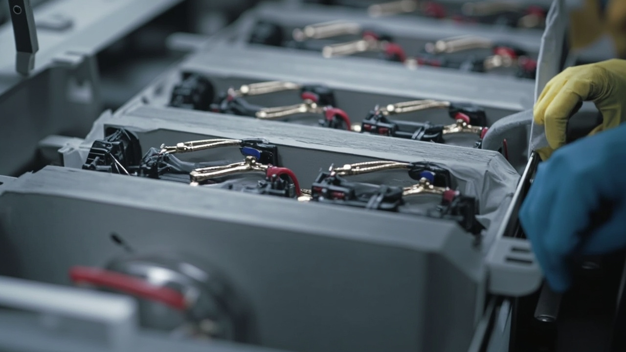
The "heart" of a new energy vehicle is the power battery pack, and the most easily overlooked yet safety-critical part inside the pack is the layers of "coating". Cells need insulation to prevent short circuits, module housings need voltage resistance, pack top covers and bottom plates need thermal insulation to delay thermal runaway, and busbars and sensing wires need insulating coverage. A large part of these functions is undertaken by dedicated coatings—they act as the battery's "invisible safety layer". This article focuses on the insulation coatings and thermal management coatings for power batteries, explaining the application locations, material systems, standards, and selection, to help battery and coating engineers build a systematic understanding.
Kexin New Materials (Guangdong) Co., Ltd. has R&D deployment in new energy protective coatings. Functional coatings for cell insulation, module thermal insulation, and pack protection have been validated for the balance of voltage resistance and heat resistance in multiple projects. The production line at the Foshan base accommodates both powder and liquid systems, capable of providing stable delivery according to the batch tempo of automakers.
I. Why batteries need coating-grade protection
A power battery is a high-voltage system (often 300–800V), and any insulation failure may cause short circuit, arc, or fire. At the same time, batteries are extremely sensitive to heat: normal operation is 15–45℃, while thermal runaway can instantly surge to 500–1000℃ and spread like "dominoes". Coatings provide a safety net at three levels: first, insulation, blocking the conductive path between cells and between cells and the housing; second, thermal insulation, delaying heat transfer to adjacent compartments during thermal runaway to buy time for escape and firefighting; third, flame retardancy, the coating itself does not support combustion and suppresses flames. These three functions are often stacked on the same coating or adjacent coatings. From a systems engineering perspective, coating is the lowest-cost, most complete-coverage, and most adaptable-to-irregular-structure barrier—unlike mica plates or aerogel felt that require cutting and fitting, it wraps metal and cells seamlessly in a "liquid-to-solid" manner, which is the fundamental reason why battery protection relies on coating-grade solutions in large-scale mass production. Further, the internal space utilization of battery packs is extremely high; cells, busbars, and sensing wires are tightly packed, and traditional solid insulation parts often "cannot be inserted" or "cannot stick firmly", while liquid coatings can provide single-part coverage to components before assembly, or local touch-up after final assembly, with flexibility far exceeding die-cut parts. This is also why in structures like CTP/CTC (cell-to-chassis) that directly integrate cells into the tray or even the vehicle body, the proportion of coatings actually increases—because there are fewer positions to place independent insulation parts, and more insulation responsibility falls on the "thin layer coated on the part surface". For OEMs, coating solutions also mean BOM simplification and process reduction, which alone is a considerable cost and tempo advantage at million-vehicle-scale production.
II. High-voltage safety and insulation failure mechanisms
High-voltage insulation failure is not always "direct breakdown". Under complex operating conditions of battery packs, insulating materials undergo multiple degradation paths: first, electrochemical corrosion, where electrolyte vapor or leakage liquid penetrates along coating micropores, causing ion migration under electric field and gradually reducing volume resistivity; second, mechanical stress cracking, where cells have 1%–3% volume expansion during charge-discharge cycles, and if the coating lacks flexibility, microcracks form, with electric field concentration at crack tips causing a sharp drop in breakdown voltage; third, partial discharge (PD), where when bubbles, impurities, or interfacial delamination exist inside the coating, local field strength exceeds the gas breakdown threshold and sustained discharge occurs, eventually penetrating the insulation through long-term electrical erosion. Understanding these mechanisms enables targeted design of coating thickness, selection of resins matched to substrates, and formulation of aging validation plans. Kexin New Materials often advises customers during vehicle validation to use "dielectric strength retention after aging" as a core acceptance metric, rather than only looking at initial values. Specifically, the electric field distribution of the coating is not uniform; field concentration occurs at conductor corners, edges, and film thickness突变, known in engineering as "edge effect", which is why busbar cut edges and cell terminal roots are most prone to problems. The design of creepage distance and clearance must also be implemented on coatings—when two equipotential conductors are isolated only by the coating surface, surface resistivity and contamination level determine the risk of surface discharge, and moisture or electrolyte contamination significantly shortens the effective creepage distance. Therefore, high-voltage insulation design cannot only calculate "is the thickness enough", but also "is the surface path long enough and the surface clean enough". At the module and pack level, engineers often use equivalent insulation diagrams to mark the design field strength (kV/mm) at each critical interface, then back-calculate the minimum film thickness at each location. This top-down method based on the three elements of "electric field—film thickness—material" has become common practice among leading battery manufacturers.
III. Interpretation of dielectric strength and volume resistivity indicators
The two cornerstone indicators of insulating coatings are dielectric strength (breakdown strength, unit kV/mm) and volume resistivity (unit Ω·cm). Dielectric strength characterizes the maximum electric field the coating can withstand per unit thickness without breakdown; common requirements for power batteries are 10–30 kV/mm, corresponding to actual locations often requiring AC 1–3 kV or DC equivalent grade without breakdown. Volume resistivity reflects the material's ability to "block leakage current"; high-quality insulating coatings are required in the range of 10^12–10^16 Ω·cm. Note that these two indicators significantly attenuate after electrolyte immersion and high-temperature-high-humidity aging, so engineering cannot only look at raw material datasheets, but must confirm margins via "retest after aging". In addition, surface resistivity and dielectric constant are often considered: surface resistivity affects surface creepage, and excessively high dielectric constant generates extra heat under high-frequency pulses, especially sensitive to fast-charging conditions. In testing methods, breakdown strength commonly uses power-frequency breakdown (AC) per GB/T 1408 or short-time breakdown per IEC 60243; samples must be prepared per standard with uniform thickness control; volume resistivity per GB/T 1410 uses a high-resistance meter to measure steady-state leakage current under high voltage for calculation. Engineering acceptance often distinguishes "type test" (full items, destructive or time-consuming) from "factory inspection" (hipot sampling, film thickness, appearance), with different frequencies and strictness. An easy pitfall is "using dielectric data of raw resin instead of actual coating measurement"—after resin cures into film, crosslink density, filler interface, and bubble rate all change dielectric behavior, so final cured coating measurement must be the basis. For multi-layer composite coatings, the dielectric behavior at interlayer bonding interfaces must also be measured separately, as delamination interfaces are often weak points. Kexin New Materials includes both initial values and comparison after 85℃/85%RH energized aging in sample reports, facilitating customer margin judgment.
IV. Full map of application locations for insulating coatings
Disassembling the battery pack, the key locations requiring insulation/thermal management coatings are in order: ① insulation coverage on the cell housing (aluminum shell, steel shell, or pouch aluminum-plastic film outer surface); ② insulation and thermal insulation on module end plates, side plates, and inner top cover; ③ conductor coverage on busbars and FPC/sensing rows; ④ all conductive parts inside the pack that may form low creepage distance, such as sheet metal parts, brackets, nuts; ⑤ thermal insulation and flame-retardant layer on inner side of pack top cover and outer surface of bottom plate; ⑥ insulation interface between water-cooling plate and housing. Each location has different voltage grade, thermal load, and mechanical deformation, so it cannot be "one coating fits all", but a one-to-one correspondence table of location—function—film thickness—material must be established. The engineering team of Kexin New Materials, when taking on projects, first step is to draw such an "insulation interface map".
V. Cell-level insulation coverage
The cell is the first line of insulation protection. Before entering the module, square aluminum-shell cells often need a 20–80 µm insulating paint sprayed on the housing surface, to block conductive short circuits between housings and between housing and liquid-cooling plate. Pouch cells rely more on the aluminum-plastic film itself for insulation, but still need touch-up coating on sides and tab areas during module stacking. The biggest difficulty of cell insulation is "thin and uniform"—too thick squeezes space and adds weight, too thin easily causes pinholes. Processes mostly use spraying or dip coating; terminal areas must be avoided or post-applied with insulation sheets. Aluminum-shell cells usually have completed formation and grading before coating, with possible residual trace electrolyte or fingerprint oil on the surface, so pretreatment cleanliness directly determines adhesion; production lines often use dust-free wiping + plasma or alcohol degreasing. The advantage of dip coating is "six-face simultaneous film, no shadow", suitable for regular square shells; spraying is easier to control locally (avoid terminals, leave welds). For cylindrical cells, insulation mostly relies on outer blue film (PET insulation film) rather than liquid coating, but the joint between top cover and housing may still be touch-up coated. The aluminum-plastic film of pouch cells is already an insulation barrier; the risk point is the tab—after multi-layer metal tabs are stacked and welded, if exposed, point coating or heat-shrink tubing insulation is needed. Kexin New Materials' low-viscosity epoxy insulation system for aluminum-shell cells achieves AC 2.5 kV no breakdown at 30 µm, balancing space and reliability, and has been adapted to multiple customers' automatic dip coating lines.
VI. Module-level insulation and thermal insulation
The module is an assembly of cells and the first "compartment" against thermal runaway spread. Module end plates and side plates need both insulation (blocking electrical contact with housing and adjacent modules) and thermal insulation (delaying single-point thermal runaway from spreading to the whole pack). Common practice is to spray insulating paint as primer, then overlay thermal-insulation flame-retardant coating, with film thickness range 100–500 µm. For CTP (cell-to-pack) structures, the module concept is weakened, cells directly combine with the pack tray, and insulation and thermal insulation responsibility shifts more to cell housing coating and pack bottom plate coating. Regardless of structural evolution, the "cell—module—pack" three-level protection logic remains unchanged, only the levels are compressed or redistributed. Another practical consideration for module insulation and thermal insulation is "repairability"—as a replaceable unit, the surface coating of the module must not flake off in sheets during disassembly, transfer, and repair, otherwise the insulation margin of secondary assembly decreases. Therefore, besides good initial performance, module coatings must withstand repeated handling and minor bumps. In thermal insulation design, film thickness of module end plates and side plates is often higher than cell housings, because end plates are adjacent to neighboring modules and are the main path of heat spread; while the inner top cover faces the internal pack space, undertaking "in-compartment fire prevention". Some high-end solutions insert independent thermal insulation inserts (mica or aerogel) between modules, forming "soft-hard combination" with coatings, where coating film thickness can appropriately yield to inserts, reducing overall weight. Kexin New Materials advocates "allocating film thickness budget according to heat spread path" in module solutions, using materials where they matter most.
VII. Busbar and sensing wire insulation
Busbars and voltage/temperature sensing rows (FPC, wire harness) are the areas with densest conductors and most disparate potential differences inside the battery pack, also high-incident areas for insulation coating accidents. Conductor coverage requires the coating to completely wrap exposed metal, no bubbles, no pinholes, and no cracking under vibration and bending. FPC rows, with flat surface, need thin coating and fast line tempo, mostly use UV-curable insulating ink; while thicker busbar aluminum/copper bars commonly use thermosetting epoxy or powder epoxy coverage. A often-overlooked detail here is "edge coverage"—conductor cut edges are sharp; if the coating cannot wet well to form rounded coverage, edge field concentration easily discharges, so the coating needs good rheology and adhesion.
VIII. Pack top cover and bottom plate thermal insulation and flame retardancy
The inner side of the pack top cover and outer side of the bottom plate are the pack's "shell defense line". When a module inside undergoes thermal runaway, the top cover must not be burned through within a certain time and not transfer heat to the occupant compartment; the bottom plate must block ground heat sources and prevent thermal runaway from spreading downward. Such coatings typically have film thickness 200–1000 µm, dominated by low-thermal-conductivity inorganic fillers (hollow glass microspheres, aerogel powder, ceramic microspheres), compounded with aluminum hydroxide/magnesium hydroxide and other flame retardants. Kexin New Materials often uses "epoxy-based thermal-insulation flame-retardant paint + local mica reinforcement" combination for pack top cover solutions; at 600 µm film thickness, thermal conductivity can be pressed below 0.12 W/(m·K), and passes UL94 V-0 and GB 38031 thermal propagation validation. It should be reminded that the top cover coating faces an asymmetric condition of "single-side fire exposure, single-side heat dissipation": fire-side temperature rises sharply, back-fire side (occupant compartment side) requires controllable temperature rise, so the coating must not only be low thermal conductivity, but also form a stable char layer or ceramic layer on the fire side to avoid burn-through. The coating's "burn-through time" is a key metric for vehicle fire safety, often evaluated jointly with vehicle thermal runaway warning and pressure relief design. The outer bottom plate also must withstand stone impact, salt spray, and wading; a single thermal insulation paint may be insufficient, requiring composite of primer (epoxy anti-corrosion) and topcoat (thermal insulation flame retardant), forming a "anti-corrosion—thermal insulation—flame retardant" sandwich structure. In addition, pack top covers are mostly aluminum or steel stamped parts, with stamping oil and brushed texture on the surface; pretreatment and primer adhesion determine whether the entire coating system will peel off in sheets under vibration and thermal cycling, which is most easily underestimated in early mass production.
IX. Powder coating systems (epoxy/polyester powder)
Powder coating is a representative of "solvent-free, uniform film thickness, eco-friendly" insulation solutions, especially suitable for batch insulation of structural parts such as housings, brackets, and trays. The principle is to make epoxy or polyester resin with curing agent and filler into dry powder, adsorb on the workpiece via electrostatic spraying, then bake at 160–220℃ to melt into film. Advantages include easy film thickness control (single pass 80–300 µm), no VOC, good edge coverage; limitations are the need for powder coating line and oven, and coverage of irregular internal cavities depends on workpiece grounding and gun accessibility. Epoxy powder has excellent adhesion and voltage resistance, polyester powder is flexible and weather-resistant, the two are often paired by location. For large-area conductive parts like battery trays, powder solutions are quite competitive in comprehensive cost and environmental friendliness.
X. Liquid insulating coatings (epoxy/polyurethane)
Liquid insulating coatings are mainly solvent-based or water-based epoxy and polyurethane, flexible in application (spraying, dip coating, brushing all possible), suitable for cells, modules, wires and many locations. Epoxy insulating paint has strong adhesion, good voltage resistance, excellent chemical resistance, but is brittle and prone to yellowing; polyurethane insulating paint is flexible, vibration-resistant, bend-resistant, more suitable for interfaces with expansion deformation, but slightly lower temperature resistance (generally long-term <150℃). Engineering often does composite of "epoxy primer + polyurethane topcoat", balancing adhesion and flexibility. Water-based is a clear trend—reducing VOC to meet environmental and occupational health requirements in coating workshops, but water-based systems are more sensitive to pretreatment and drying window, requiring process coordination.
XI. UV-curable insulating ink
UV insulating ink is based on acrylate oligomers, cured in seconds under ultraviolet light, the high-speed mass production preferred for thin FPC/wire coverage. Its advantages are "fast, thin, flat"—film thickness controllable at 15–60 µm, line speed up to several meters per minute, and no oven occupation. Limitations are also obvious: UV is straight-line light, shadow areas (covered conductor back, deep grooves) cannot cure, requiring dual curing (UV+thermal) or local touch-up; and acrylic systems have weaker long-term heat and electrolyte resistance than epoxy. Therefore UV ink is mostly positioned for "low-voltage, thin-layer, fast-line" wire scenarios, not high-voltage main insulation.
XII. Silicone and organosilicon insulation systems
Organosilicon (silicone) coatings, with extremely wide temperature range (-50℃ to 200℃ long-term, higher short-term), excellent flexibility and electrical insulation, occupy a place on high-deformation interfaces (such as pouch cells, elastic busbar pads). Silicone can be room-temperature cured (RTV) or heat cured (HTV), buffering cell expansion and suppressing microcracks. Disadvantages are low mechanical strength, easy dust adsorption, need primer treatment for metal adhesion, and higher unit price. In locations needing "both insulation and deformation absorption", organosilicon is often used as the elastic layer in composite systems.
XIII. Ceramizable and inorganic insulating coatings
Ceramizable coating is a recently emerged "passive fire protection" concept: normally organic polymer provides insulation and flexibility; once encountering high temperature (about above 600℃) the organic component decomposes, inorganic fillers (wollastonite, mica, glass fiber) sinter into a hard ceramic shell, blocking flame and heat. Such coatings maintain structural integrity under extreme thermal runaway conditions, a strong candidate for pack top covers and module partitions. Pure inorganic coatings (such as silicate-based) sacrifice flexibility for extreme temperature resistance, mostly used for local reinforcement. Kexin New Materials has formula reserves in ceramizable thermal-insulation flame retardant direction, aiming to combine "normal insulation + extreme ceramization" into one.
XIV. Thermal management coatings: thermally conductive vs thermally insulating
Thermal management coatings are both called "thermal management", but the direction may be opposite, must distinguish two types: ① thermally conductive—quickly conduct cell working heat away, coating filled with alumina, boron nitride, aluminum nitride and other high-thermal-conductivity fillers, thermal conductivity 1–5 W/(m·K), used for thermal interface between cell side and liquid-cooling plate; ② thermally insulating—"confine" heat near the runaway source, low-thermal-conductivity fillers dominant, used to prevent spread. The two coexist and complement in the same battery pack: normal operation relies on conductive coating for heat dissipation, thermal runaway relies on insulating coating for isolation. Confusing the two is a common selection error—misapplying insulating layer to interfaces needing heat dissipation causes heat accumulation; vice versa. In actual battery packs, thermally conductive coatings are mostly used for the "thermal interface material (TIM)" role between cell large face and liquid-cooling plate, requiring not only good thermal conductivity but also certain compression rebound to fill micro-unevenness between cell and cold plate, and electrically insulated (to avoid cold plate electrification hazard). This gave birth to the special category of "insulating thermally conductive"—using insulating boron nitride, alumina as fillers, resin matrix also selected high-insulation epoxy/organosilicon, enabling the coating to have both 1–5 W/(m·K) thermal conductivity and >10^12 Ω·cm resistivity. Thermally insulating coating is the opposite, replacing fillers with low-thermal-conductivity hollow structures and minimizing resin continuous phase thermal conductivity. An interesting engineering compromise is "zoned design": within the same pack, cell working zone uses conductive, high-runaway-risk partition uses insulating, achieving "conduct where needed, insulate where needed" via coating formula differences. Kexin New Materials has practiced zoned conductive/insulating solutions on multiple models, cooperating with customer thermal simulation to determine target thermal conductivity for each zone.
XV. Insulating fillers: aerogel, hollow microspheres, ceramic microspheres
The core of insulating coatings is fillers. Hollow glass microspheres (HGM) are light, low thermal conductivity, easy to disperse, the cost-effective choice; ceramic microspheres have higher temperature resistance; aerogel powder (SiO2 aerogel) thermal conductivity can be as low as 0.015 W/(m·K) level, the thinnest and lightest solution at same effect, but high cost, brittle, easy to absorb water, need surface modification and good compatibility with resin. Filler dosage (volume fraction 30%–60%) and particle size gradation directly determine thermal conductivity and film thickness; engineering must balance "low thermal conductivity" with "applicable viscosity, low cracking". Kexin New Materials' process on aerogel powder surface modification enables stable dispersion in epoxy systems without excessive viscosity increase. Regarding gradation, a practical trick is "large balls fill voids, small balls fill seams"—using hollow microspheres of different particle sizes compounded, can obtain lower thermal conductivity and denser packing at same volume fraction, reducing internal radiative heat transfer channels; but too large particle size span also brings sedimentation and unstable application, requiring thixotropic and dispersing agents. Besides thermal conductivity, filler electrical performance is also key: fillers used for insulation and thermal insulation must themselves be high-insulation (such as glass, ceramic, SiO2), absolutely no conductive impurities; while thermally conductive fillers (boron nitride, alumina) are insulating, but if containing free metal ions will contaminate resin, need control ion content to meet electrolyte compatibility. Filler oil absorption determines the extent of "eating" the resin; high oil-absorption fillers need more resin wetting, indirectly pushing up film thickness and cost, so read the filler property sheet thoroughly when selecting.
XVI. Phase-change endothermic and thermal runaway delay coatings
Phase-change (PCM) coatings integrate "heat absorption" into protection: the coating embeds phase-change microcapsules with high fusion enthalpy (such as paraffin, ester), when local temperature exceeds the phase-change point, the material absorbs heat and changes phase, absorbing large latent heat, smoothing temperature rise, delaying the time to reach thermal runaway critical. It is often compounded with insulating fillers, forming "first absorb heat, then insulate" double buffer. Limitation is phase-change material may leak or degrade over long cycles, requiring microcapsule encapsulation and sealing design, and phase-change temperature window must match battery thermal runaway path. Such coatings are suitable as "active—passive" hybrid protection layer for module partitions or top covers.
XVII. Flame retardant systems: aluminum hydroxide, magnesium hydroxide, expanded graphite
Flame retardancy does not rely on "non-combustibility", but on "smoke suppression, flame retardancy, and char formation". Aluminum hydroxide (ATH) and magnesium hydroxide (MDH) are the mainstream inorganic flame-retardant fillers; when heated they decompose to release water and metal oxides, which both dilute combustible gases and absorb heat, and are low-smoke and non-toxic; expandable graphite expands sharply in fire to form a worm-like char layer, physically isolating oxygen and heat; in addition, there are phosphorus-based and nitrogen-based synergists. The flame-retardant formulation must be compatible with the base material, and excessive addition will sacrifice mechanical properties and adhesion. UL94 V-0 is a common flame-retardant grade threshold, but what is more critical for batteries is "not promoting combustion and not contributing energy under thermal runaway", so flame-retardant verification should be combined with GB 38031 thermal propagation and nail penetration scenarios, rather than looking at UL94 small samples in isolation. In engineering, the flame-retardant system often uses "synergistic compounding": ATH/MDH provide endothermic dehydration, expandable graphite provides a physical char layer, and phosphorus-nitrogen systems promote char formation and capture free radicals. The three are proportioned according to the base material and working conditions, which can achieve V-0 and reduce smoke density without excessive addition. It is worth noting that flame-retardant fillers are mostly inorganic powders, which increase coating hardness and brittleness; for flexible deformation interfaces that require flexibility, they should be used with caution or replaced with flexible flame-retardant mechanisms (such as silicone-based). Smoke toxicity is also a dimension of occupant safety. Battery thermal runaway itself produces toxic smoke; if the coating releases hydrogen halides when burning, it will make things worse. Therefore, halogen-free flame retardancy is a clear industry direction. Kexin New Materials adheres to a halogen-free route in its formulations, mainly using hydroxides and expansion systems to avoid secondary hazards contributed by halogens.18. Material System Comparison Table
| System | Advantages | Limitations | Applicable Parts |
|---|---|---|---|
| Epoxy insulating paint | Strong adhesion, good voltage resistance, excellent liquid resistance | Brittle, prone to yellowing | Cell/module insulation, priming |
| Polyurethane insulation | Flexible, vibration-resistant, bend-resistant | Slightly low temperature resistance (<150℃) | Wiring, elastic interfaces |
| Powder epoxy | Uniform film thickness, solvent-free, good edge coverage | Requires curing equipment and oven | Shell/tray batch production |
| UV insulating ink | Second-level fast curing, thin, flat | Shadow areas hard to cure, weak heat resistance | FPC/wiring thin coating |
| Silicone coating | Wide temperature range, high flexibility | Low strength, requires primer | Pouch/deformation interfaces |
| Heat-insulating flame-retardant paint | Integrated heat insulation and flame retardancy | Large film thickness | Pack inner wall/top cover |
| Aerogel coating | Extremely low thermal conductivity, light and thin | High cost, brittle, easy to absorb water | High-end heat insulation |
| Ceramifiable coating | Extreme ceramization, structure preservation | Hard in normal state | Top cover/partition reinforcement |
19. Film Thickness Design and µm Control
Film thickness is the core variable for insulation and heat insulation, but it is not "the thicker the better". In terms of insulation, breakdown voltage increases approximately linearly with film thickness, but thick films bring cracking, sagging, weight gain, and cost; in engineering, the minimum required film thickness is back-calculated from the voltage level of the part and a margin is left (usually 2–3 times). In terms of heat insulation, thermal resistance is proportional to film thickness, but excessive thickness will squeeze space, increase weight, and reduce workability. Typical film thickness ranges: cell insulation 20–80 µm, wiring 15–60 µm, module insulation and heat insulation 100–500 µm, pack top cover/base plate 200–1000 µm. Control methods include wet film gauges, online laser thickness measurement, and destructive cross-section microscopy; batch production lines should achieve per-piece or sampled film thickness closed-loop. In mass production engineering, there are at least four sources of film thickness fluctuation: coating viscosity drift with temperature, unstable spray gun pressure and movement, differences in workpiece grounding/charging (powder), and leveling changes caused by workpiece temperature. Therefore, a stable coating parameter window is more important than "single-time compliance" — when transferring processes to customers, Kexin New Materials provides an "adjustable parameter band" rather than a single value, so that the production line still falls within the qualified zone when equipment fluctuates. Another often overlooked point is the "non-linearity" of film thickness and performance: when the film thickness is below a certain critical value, the probability of pinholes surges and insulation reliability drops cliff-edge; exceeding a certain upper limit increases the risk of cracking and sagging sharply. Finding the inflection point of this "S-curve" is the essence of film thickness design. For critical main insulation parts, it is recommended to use Statistical Process Control (SPC) to monitor film thickness CPK, rather than just checking whether a single point is qualified.
20. Curing Process and Parameters (Thermoset/UV/Powder)
Curing determines the final performance of the coating. Thermoset epoxy commonly uses 120–180℃, 10–30 min; insufficient temperature leads to incomplete crosslinking, and reduced voltage resistance and liquid resistance; UV curing needs to match light intensity (mJ/cm²) and line speed; insufficient curing makes the surface sticky, while overexposure causes yellowing and embrittlement; powder coating oven 160–220℃, 5–15 min for melting and leveling. The curing window must also be compatible with the substrate — FPC is not high-temperature resistant and requires low temperature or UV; aluminum shell can withstand higher temperatures. When delivering formulations, Kexin New Materials attaches a "curing window recommendation", giving the temperature—time—performance curve to the customer's production line engineering for reference. Whether curing is complete cannot be judged only by "surface dry and non-sticky", but should be indirectly determined by Differential Scanning Calorimetry (DSC) to measure residual reaction heat, or solvent residue/hardness/solvent wipe resistance. Under-cured coatings have low crosslink density, reduced volume resistivity and electrolyte resistance, and are prone to further reaction, shrinkage, and cracking during subsequent thermal cycles; over-curing causes resin embrittlement and reduced adhesion. For powder coatings, melting leveling and crosslinking occur simultaneously; the uniformity of the oven temperature curve (heating section, holding section, cooling section) determines batch consistency, and a furnace temperature tracker is an essential diagnostic tool. UV systems need to look at "deep curing" — for thick films or those with high filler content, UV penetration is insufficient, the surface is hard but the bottom is soft, requiring dual curing or adjustment of photoinitiator ratio. Turning curing from "experience" into "curves and data" is the prerequisite for stable coating mass production.
21. Coating Equipment and Automation
Battery coating mass production cannot be separated from automation. Cells and modules mostly use robotic electrostatic spraying or rotary bell spraying to ensure uniform film thickness and edge coverage; shells/trays use powder electrostatic lines + automatic recovery; wiring uses UV ink roller coating/spraying + UV curing tunnel; dip coating is suitable for mass consistent coating of regular small parts. Online inspection (thickness measurement, visual defects, electrical inspection) and MES networking are the basis for quality traceability. The experience of Kexin New Materials' Foshan production line shows that the coating cycle must match the cell/module assembly cycle, otherwise even the best coating will be stuck at the "cannot scale up" stage.
22. Pretreatment and Substrate Adaptation
70% of coating performance depends on pretreatment. Aluminum shells need degreasing, micro-etching, or passivation to remove oxide film and oil stains; steel parts need derusting, phosphating, or zirconization; nickel/copper busbars need degreasing and activation; FPC needs plasma or chemical roughening to improve adhesion; pouch aluminum-plastic film should avoid solvent swelling. Substrate surface energy, roughness, and cleanliness directly determine adhesion and long-term reliability. Kexin New Materials will provide a "substrate—coating matching package" for the customer's specific substrate at the formulation end, including recommended pretreatment processes and primers, to avoid "qualified coating but substrate drags behind". Specifically for battery parts, if the passivation film of the aluminum shell is too thick it will block adhesion, so the passivation process needs to be controlled; weld slag and uneven zinc layer on steel trays cause local poor adhesion, requiring grinding and pretreatment; copper busbars are prone to oxidation and film formation, so the operation window should be short or a primer added; FPC's polyimide substrate has low surface energy and requires plasma or sodium naphthalene treatment to improve wetting. A more hidden risk is "contamination migration" — cross-contamination of pretreatment bath liquids, glove oil stains, and workshop dust falling on the surface to be coated will all form weak interfaces after curing and crack during thermal cycles. Therefore, cleanliness management must extend to the whole chain from "the last step before coating to curing", not just the pretreatment station. For the situation where insulated cells are crushed by fixtures during module assembly, Kexin New Materials recommends adding a "post-assembly local touch-up + electrical inspection" fallback process.
23. Online Inspection and QC (hipot, dielectric, thickness)
The "three-piece set" of quality control is voltage resistance (hipot, step-up to set value without breakdown), insulation resistance (megohmmeter/high-resistance meter to measure volume resistivity), and film thickness (online laser or wet film gauge). Hipot commonly uses AC or DC, with thresholds set by part voltage level and margin left; breakdown means scrap. Further sampling can be done for dielectric strength (kV/mm), performance after salt spray/humid heat, adhesion (cross-cut, pull-off). For high-voltage main insulation parts, 100% electrical inspection is recommended; for non-critical parts, sampling is acceptable. Kexin New Materials implements "batch sample retention + aging tracking", closing the loop between factory data and failure feedback after customer vehicle assembly. The setting of electrical inspection thresholds emphasizes "leave margin but not overkill": too low a threshold scraps qualified products and lowers yield; too high lets hidden dangers pass. In engineering, the test voltage is usually back-calculated from "design field strength × film thickness × safety factor (2–3 times)", then fine-tuned with historical failure data. In addition to voltage resistance and resistance, more and more production lines introduce machine vision for appearance (sagging, missed coating, particles), online laser thickness measurement, and edge coverage scoring, forming a "electrical + shape + thickness" trinity. At the data level, it is recommended to upload each piece's electrical inspection result, film thickness, and batch number to MES for quality traceability — once an insulation-related recall occurs at the vehicle end, the batch and process deviation can be quickly located. This is also one of the hard requirements of car manufacturers for tier1 coating and painting suppliers.
24. Thermal Cycle and Thermal Shock Verification
Batteries experience thousands of charge-discharge cycles and seasonal temperature differences in their life cycle; the coating repeatedly expands and contracts between -40℃ and 85℃ (or even wider), and cracks if flexibility is insufficient. Verification methods include thermal shock (rapid temperature change), thermal cycle (slow temperature change), and temperature—humidity—voltage combined aging. The criteria are dielectric strength and adhesion retention after cycling, no visible cracks, no delamination. What is often underestimated here is "energized aging" — doing temperature-humidity cycles under working voltage can better expose electrochemical corrosion paths. Kexin New Materials recommends including energized aging as a mandatory item in vehicle model verification.
25. Partial Discharge and Pinhole Detection
For high-voltage main insulation, missing one pinhole or bubble may evolve into partial discharge or even breakdown during operation. In addition to hipot, partial discharge detection (monitoring discharge quantity pC at set voltage, scrap if exceeding threshold) and pinhole detection (high-voltage salt water bath or spark leak detection) can be introduced. Such means are especially important for large-area thin insulation such as pack top covers and module end plates. Moving PD detection from "after-the-fact" to "online" is an effective lever to improve pack insulation reliability, and also an implicit threshold for leading car manufacturers on tier1. The sample strategy for thermal cycle verification is also critical: do not only test "brand-new parts", but must test the state "after charge-discharge aging, electrolyte immersion, or even slight mechanical damage", because real-vehicle coatings work in a degraded state. A repeatedly verified rule is — coating failure mostly occurs at the inflection point of "material already aged + working condition superposition", and looking only at new-part performance seriously overestimates the margin. Therefore, in vehicle model verification, Kexin New Materials recommends setting up an "accelerated aging ladder": first electrolyte immersion, then temperature-humidity energized aging, finally thermal shock, superimposed step by step, observing the dielectric and adhesion retention curves, finding the cycle count corresponding to the inflection point, and then converting to vehicle life equivalent. This "stepwise aging" exposes real risks better than a single cycle, and is more persuasive in car manufacturer reviews.
26. Common Defects and Countermeasures Table
| Defect | Cause | Countermeasure |
|---|---|---|
| Insulation breakdown | Thin film/pinhole/impurity | Increase film thickness, remove pinholes, purify environment |
| Poor adhesion | Substrate oil stain/delamination from expansion | Strengthen pretreatment, choose flexible system |
| Insufficient heat insulation | High thermal conductivity/thin film | Add heat-insulating filler, increase film thickness |
| Failure on liquid contact | Poor electrolyte resistance | Switch to liquid-resistant resin, do immersion verification |
| Flame retardancy not up to standard | Insufficient flame-retardant filler | Increase flame-retardant ratio, add synergist |
| Sagging in thick coating | Low viscosity/one-time too thick | Increase thixotropy, thin spray multiple passes |
| Microcracks | Insufficient flexibility/expansion | Change to elastic system, reduce film thickness gradient |
| Partial discharge | Bubble/delamination/edge | PD detection, optimize wetting and edge wrapping |
| Yellowing and embrittlement | UV overexposure/thermal oxygen | Control curing, add antioxidant |
27. Troubleshooting Cases (Cracks, Porosity, PD)
The three most typical failures in practice: first, microcracks in cell insulating paint, mostly rooted in aluminum shell cyclic expansion exceeding the coating's elongation at break; the countermeasure is to switch to high-elongation polyurethane or reduce film thickness gradient and add primer; second, porosity in module heat-insulation layer, from poor spray atomization or filler agglomeration; the countermeasure is to optimize atomization parameters and filler dispersion, and add online visual inspection; third, busbar edge partial discharge, rooted in sharp cut edges and incomplete coating coverage; the countermeasure is to adjust rheology to form rounded edge coverage and increase PD detection ratio. The "failure library" summarized by Kexin New Materials in multiple vehicle model introductions has become a reference baseline for early risk avoidance in new projects.
28. Standard System (GB 38031, ISO, UL94, IEC)
Battery coatings are not accepted in isolation, but must fall under vehicle and battery mandatory standards. Domestic core standards include GB 38031 (Safety requirements for power batteries of electric vehicles, including thermal propagation, nail penetration, external fire, etc.), GB/T 31467 series; international levels include ISO 6469 (electrical safety), IEC 62619/62660 (battery safety and cycle), UN 38.3 (transport); flame retardancy often references UL94, GWIT/GWFI (glow wire). Insulation itself can refer to GB/T 1408 (breakdown voltage), GB/T 1410 (resistivity), IEC 60243, etc. In engineering, "coating performance" must be mapped to "battery pack level verification", because the final responsibility lies in pack safety rather than a single coating. Kexin New Materials annotates corresponding standard clauses item by item in its proposal. Supplement a few often-asked standard details: GB 38031's "thermal propagation" requirement means that after a single cell thermal runaway, the whole pack shall not catch fire or explode within the agreed time and shall give a warning; as a passive delay layer, the coating must maintain structural integrity within this time window, so verification often puts the coating sample together with the whole pack for nail penetration/heating trigger tests; GB/T 31467.3 involves insulation retention after vibration and mechanical shock; ISO 6469-3 specifies insulation resistance and contact protection for high-voltage systems; although UN 38.3 is transport safety, its nail penetration, crush, and thermal chamber items also indirectly test coating performance under extremes. Car manufacturer internal standards are often stricter than national standards, e.g., a German manufacturer's busbar insulation requires zero discharge under a specific PD threshold and 1000-hour energized humid heat. When making a proposal, be sure to obtain the customer's enterprise standard list first and correspond item by item, to avoid the awkwardness of "national standard passed but enterprise standard failed".
29. Environmental and VOC Regulations
Environmental compliance of coatings is increasingly tightening. Solvent-based systems face VOC emissions and occupational health pressure; water-based, powder, and UV are the three mainstream decarbonization paths. Domestic coating VOC emissions are constrained by the "Air Pollution Prevention and Control Law" and local limits; vehicle manufacturers also include "low VOC coating proportion" in supply chain assessment. For battery factories, workshop sealing and exhaust gas treatment costs must also be counted in selection. Kexin New Materials' Foshan production line layout in powder and water-based systems conforms to this compliance trend, helping customers reduce carbon and compliance risks in the coating process.
30. Supply Chain and Localization
Power battery coatings were highly dependent on imported resins and high-end fillers in the past; in recent years, domestic substitution has accelerated: epoxy/polyurethane matrices, ATH/MDH flame retardants, and hollow microspheres are basically localized; aerogel powder, boron nitride, and other high-end fillers are also breaking through. The value of localization is not only cost reduction, but also lead time and localized technical service — battery factory production line commissioning requires coating suppliers to quickly respond to formula fine-tuning. As a local enterprise, Kexin New Materials has geographical advantages in response speed and customization, and can cooperate with the agile development rhythm of car manufacturers. From the perspective of supply chain resilience, the "bottleneck" points of battery coatings are mainly concentrated in two types: one is the batch stability of high-end fillers (particle size and thermal conductivity of aerogel powder, purity and ion content of boron nitride), and the other is the liquid and temperature resistance balance of special resins (such as electrolyte-resistant epoxy, flexible polyimide precursor). Localization is rapidly catching up in these two aspects, but engineers must do "equivalence verification" when switching to domestic materials — it is not just changing a brand name, but re-running the dielectric, liquid resistance, and aging three-piece set to confirm that the performance curve does not drift. When introducing domestic fillers, Kexin New Materials does small-test — pilot — batch three-stage confirmation, and includes key physical properties (water absorption, ion content, particle size distribution) in incoming inspection, to avoid raw material fluctuation ruining the whole batch of coating. For car manufacturers, choosing a local coating supplier with "independent formula capability + controllable supply chain" is more conducive to mass production stability than simply comparing unit price.
31. Kexin New Materials Foshan Production Line Practice
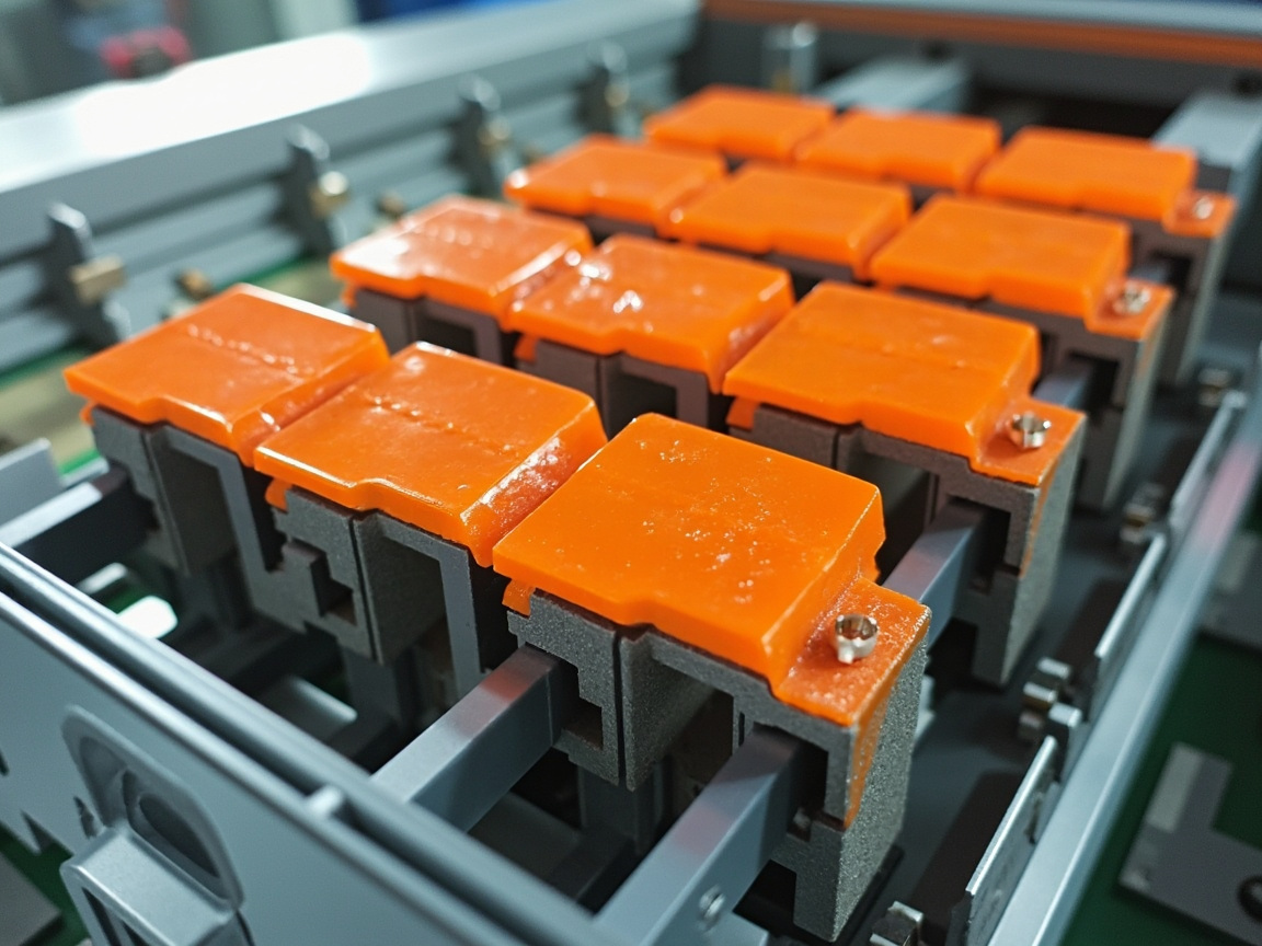
Kexin New Materials (kexinMaterials) is located in Foshan, focusing on new energy protective functional coatings, covering insulation, heat insulation, flame retardancy, and thermal conductivity systems. Its Foshan base has both powder line and liquid line capabilities, and can do batch delivery of cell insulation, module heat insulation, and pack top cover flame retardancy according to vehicle model cycle. In practice, Kexin emphasizes the "three charts" working method: insulation interface map (part—function), curing window chart (temperature—time—performance), failure comparison chart (defect—cause—countermeasure), depositing experience into reusable engineering methods. Multiple projects have verified its comprehensive balance in voltage resistance, electrolyte resistance, and thermal shock.
32. Selection Framework and Decision Tree
Faced with numerous systems, it is recommended to use a decision tree to narrow down: Step 1, define the location (cell/module/busbar/pack), as different locations have huge differences in voltage level, deformation, and thermal load; Step 2, define the functional priority (primarily insulation, primarily thermal insulation, or primarily thermal conduction) to avoid confusion in direction; Step 3, define process constraints (whether the production line can adopt powder/UV, upper limit of curing oven temperature, takt time); Step 4, define environmental and cost boundaries (water-based/powder to reduce VOC, domestic substitution to reduce cost); Step 5, conduct "post-aging retest" verification and leave a margin. Kexin New Materials often embeds this framework into early technical communication with customers to shorten the distance from sampling to mass production. When implementing the framework, several experiences are worth emphasizing: First, do not be misled by "single highest performance"—a coating with extremely high dielectric strength but poor flexibility is prone to cracking at expanding interfaces, and should be comprehensively scored by location weight; Second, establish a mechanism of "candidate shortlist + aging retest elimination", initially select 3–4 suppliers or 3–4 formulations, and compare retention rates under the same aging conditions, which is far more reliable than measuring initial values once; Third, calculate cost based on "effective protection per unit area" rather than "price per kilogram"—if a high-price aerogel achieves the same thermal insulation at a thinner film thickness, the comprehensive cost may be lower; Fourth, reserve production line compatibility—even if the formulation is the best, if the customer's existing line cannot cure or spray, the retrofit cost must be evaluated. The approach of Kexin New Materials is to first provide a free "location—function—process" matching proposal, then send samples for parallel verification, shifting selection risk forward for resolution.
33. New Challenges of Fast Charging and High-Nickel to Coatings
Fast charging (above 4C) and high-nickel ternary (NCM811 and higher) push batteries to higher operating temperatures and more severe thermal runaway risks. The impact on coatings is twofold: the operating state is hotter, requiring more efficient thermal conductive interfaces; the runaway state is more violent, requiring thermal insulation and flame-retardant layers to withstand more. At the same time, high-nickel systems are more sensitive to electrolyte leakage, raising the threshold for coating liquid resistance. The pulsed electric field brought by charge-discharge rate under fast charging also requires low dielectric constant and low loss to reduce extra heating. Targeting the high-nickel fast-charging platform, Kexin New Materials is developing a composite solution of "low-dielectric thermal conductive primer + ceramicizing thermal insulation topcoat". To elaborate, the logic of this composite solution is: the bottom layer is close to the cell, undertaking daily heat dissipation and insulation, requiring low dielectric constant (reducing dielectric loss heating under pulsed electric field) and high thermal conductivity (quickly directing fast-charging heat to the cold plate); the top layer faces the adjacent compartment, undertaking thermal insulation and ceramization during runaway, requiring low thermal conductivity and high-temperature ceramicization. The interfacial bonding between the two layers is a technical difficulty—two layers with large modulus difference are prone to delamination under thermal cycling, requiring a gradient transition layer or flexible intermediate layer to bridge. Apart from materials, fast charging also changes the "verification rhythm": to seize market launch, automakers compress the verification cycle, so coating suppliers must use accelerated aging models to give credible life predictions, rather than waiting for the whole vehicle to complete the full cycle. When cooperating with fast-charging projects, Kexin New Materials has incorporated the correlation modeling of "charge rate—temperature rise—coating degradation" into early simulation to lock high-risk interfaces in advance.
34. Trend of Integrated Multifunctional Coatings
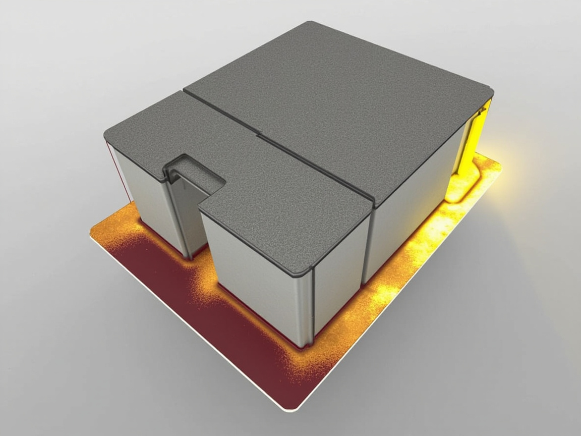
The industry is moving from "one function one coating" to "one coating multi-function composite design": the same coating combines insulation—thermal insulation—flame retardancy, even adding thermal conduction or heat absorption, to reduce processes, weight, and cost. Implementation paths include multilayer gradient coating (bottom insulation, middle thermal insulation, top flame retardancy) and single-coat multifunctional formulation (filler compounding makes insulation and thermal insulation in one body). The difficulty is the performance trade-off among multiple functions—for example, high filler content improves thermal insulation but sacrifices flexibility and adhesion, requiring resin modification and gradation optimization to solve. Kexin New Materials' reserves in multifunctional gradient coatings correspond to this cost-reduction and efficiency-improvement main line.
35. Safety Redundancy and Three-Dimensional Firewall
Single-point protection is insufficient to cope with extreme thermal runaway; the industry consensus is "safety redundancy": deploy defense at cell, module, and pack three levels, with coatings coordinating with mica board, aerogel felt, fireproof adhesive, and exhaust valve to form a three-dimensional firewall. The role of coatings is an "ubiquitous underlying barrier"—it may not alone withstand all thermal load, but can buy critical time before other passive components are in place. The design philosophy should shift from "single-layer optimal" to "system margin", leaving failure buffer at each level. Kexin New Materials repeatedly emphasizes in scheme communication: coating is a link in the redundancy chain, not a replacement for structural parts.
36. Outlook: Technology Roadmap for the Next Five Years
Looking forward to the next five years, battery protective coatings will evolve along four main lines: ① high-temperature-resistant ceramicization combined with aerogel to cope with 1000℃-level short-term thermal runaway; ② low film thickness high thermal insulation to meet lightweight and CTP/CTC compressed space; ③ water-based/powder/UV comprehensively reducing VOC, compliance-driven; ④ digitalization—coating formulation, film thickness, and electrical inspection data connected to the battery full-life-cycle traceability. At the same time, as new systems such as solid-state batteries and sodium-ion batteries mature, coating demands will also shift (e.g., solid-state batteries have lower requirements for electrolyte resistance, but still have rigid demand for interface insulation and thermal management). Kexin New Materials bets on the long-term main line of "function integration + safety redundancy + localized agile service", and will continuously invest in new-energy protective coating R&D. Finally, a practical suggestion for battery and coating engineers: treat the coating as a "system part with the same life as the cell", rather than "an optional surface treatment". This means from the design end, insulation interface, film thickness budget, curing window, and aging verification must be incorporated into the vehicle development process, rather than patched before mass production. Only when coating suppliers, battery factories, and OEMs align standards and scenarios in the early stage can this "invisible safety layer" truly hold the bottom line under millions of cycles and extreme conditions. Kexin New Materials (kexinMaterials) is willing to serve as a localized partner in this chain, working with the industry to make new-energy battery protection more reliable, lighter, and greener.
FAQ
Q1: Does every layer of the cell need insulation coating?
Not every layer, but key conductive interfaces (cell casing, module end plate, busbar, wiring) must be insulation-covered to form multi-level short-circuit prevention. Specifically determined by battery pack design and voltage level.
Q2: Can thermal insulation coating prevent thermal runaway?
It cannot "prevent", but can "delay"—when a single cell undergoes thermal runaway, it slows heat transfer to adjacent compartments, buying time and a fire window; it is a part of safety redundancy, not a panacea.
Q3: Is insulation coating resistant to electrolyte?
It must be. Lithium electrolyte will chronically erode ordinary coatings causing insulation drop, requiring liquid-resistant resins (such as special epoxy/polyimide types) and long-term immersion verification.
Q4: How to choose between UV insulation ink and epoxy paint?
Thin coverage on wiring/FPC, need fast line—choose UV; thick insulation on cell/module, need strong adhesion—choose epoxy/polyurethane. Determined by location and production line.
Q5: What is good about aerogel coating?
Extremely low thermal conductivity, thinner and lighter film at same thermal insulation effect, suitable for weight-sensitive battery packs, but high cost and brittle, requiring配套 protection.
Q6: What strong standards must battery coatings pass?
Mainly battery safety strong standards (such as GB 38031), flame retardancy (UL94, etc.), voltage resistance and insulation, as well as the automaker's own thermal shock and nail penetration verification; full set must be passed before mass production.
Q7: Is thicker film always better for insulation?
The trend is correct, but thick film brings cracking, sagging, weight gain, and cost; the minimum film thickness should be reverse-derived from location voltage level with 2–3 times margin, rather than blindly thickening.
Q8: Why is it recommended to do energized aging verification?
Ordinary temperature-humidity cycling does not apply voltage, making it difficult to expose chronic insulation attenuation caused by electrochemical corrosion; energized aging is closer to real vehicle conditions and can detect hidden dangers in advance.
Q9: Is partial discharge detection necessary?
It is very necessary for high-voltage main insulation parts (upper cover, end plate); it can catch pinholes, bubbles, incomplete edge coverage and other hidden dangers that hipot may miss; it is recommended to gradually move forward to online detection.
Q10: Will water-based coating be inferior to solvent-based?
The performance gap is narrowing, and water-based is more eco-friendly and low VOC; the limitation is more sensitive to pre-treatment and drying, requiring process coordination; which supplier and which system to choose should be combined with production line conditions.
Q11: What special requirements do fast-charging models have for coatings?
Higher operating temperature requires more efficient thermal conductive interface and stronger thermal insulation/flame retardancy; pulsed electric field requires low dielectric constant and low loss; high-nickel systems also require stronger liquid resistance.
Q12: What support can Kexin New Materials provide?
Kexin New Materials (kexinMaterials) Foshan production line covers powder and liquid multi-systems, able to provide engineering support and batch delivery from insulation interface map, curing window to failure comparison.
Further Reading
- ESS Fireproof Coatings — Fireproof and thermal-insulation supporting for battery systems.
- Semiconductor Packaging Protective Coatings — Advanced scenarios of high-reliability insulation protection.
- PVD Supportive Coatings — Design ideas for metallization and insulation coordination.