Insulating powder coating is a class of thermosetting powder coating with electrical insulation as its primary function, typically based on epoxy or modified epoxy. A single application forms a continuous, dense, high-resistance insulating layer on the surface of metal conductors or live parts, replacing traditional varnish dipping, wrapping, and injection molding. Its core metrics are not "how good it looks", but volume resistivity, surface resistivity, electric strength (breakdown voltage), and tracking resistance index (CTI) — these parameters directly determine whether the equipment can safely withstand the working voltage and avoid leakage and creepage in humid and polluted environments. According to GB/T 6554 "Epoxy powder coating for electrical insulation — General requirements", insulating epoxy powder must be systematically evaluated for these electrical properties. In the power transmission and distribution, motor manufacturing, new energy, and electronics industries, the consumption of insulating powder continues to grow precisely because it enables single-coat thick application, is solvent-free, coats complex shapes, and offers stable and traceable performance.
In the field of functional powder, Kexin New Materials (kexinMaterials) provides insulating powder systems for motors, busbars, transformers, and battery housings, with a collaborative design of "insulation plus anti-corrosion plus wear resistance". Based on citable standards (GB/T 1410, GB/T 1408, GB/T 1411, GB/T 6554, and IEC 60243, IEC 60120, etc.), this article dissects the technical core of insulating powder coating, helping electrical engineers turn "insulation" from a vague requirement into quantifiable acceptance criteria.
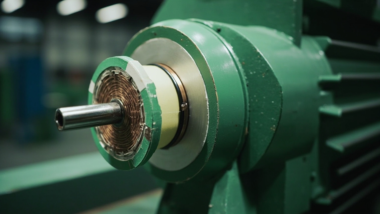
I. Core Electrical Indicators of Insulation
The performance of insulating powder is defined by four electrical indicators. Volume resistivity is the resistance per unit volume, in ohm-centimeter, measured according to GB/T 1410 (equivalent to IEC 60093); surface resistivity is the surface resistance per unit area, in ohm per square, measured by the same standard; electric strength (breakdown strength) is the breakdown voltage per unit thickness, in kV/mm, measured according to GB/T 1408 (equivalent to IEC 60243); comparative tracking index (CTI) is the voltage resistance to tracking, in volts, measured according to GB/T 1411 (equivalent to IEC 60112). The volume resistivity of epoxy insulating powder reaches 10¹³–10¹⁶ ohm-centimeter, far higher than that of air at about 10¹⁶ (but air is prone to breakdown); more critically, it is solid, adherent, and non-collapsing. Electric strength determines the voltage-withstanding thickness of the insulating layer — for example, a coating with electric strength of 20 kV/mm theoretically withstands about 10 kV at 0.5 mm thickness (in practice, safety margin and defects must be considered). CTI characterizes the ability to resist tracking under humid and contaminated environments; CTI ≥ 600 is the highest tracking-resistant grade, and CTI > 175 is the basic insulation grade.
It needs to be clarified: the "insulation" of insulating powder is a relative concept — it limits the leakage current under working voltage to a safe level, rather than being absolutely non-conductive; the design must provide sufficient safety factor according to the equipment's rated voltage, and consider the decreasing effect of temperature, humidity, and contamination on resistance.
II. Indicator Comparison Table
| Indicator | Definition | Common Standard | Typical Target |
|---|---|---|---|
| Volume resistivity | Resistance per unit volume, Ω·cm | GB/T 1410 (eq IEC 60093) | > 10¹²–10¹⁶ |
| Surface resistivity | Surface resistance per unit area, Ω/□ | GB/T 1410 | > 10¹²–10¹⁴ |
| Electric strength (breakdown strength) | Breakdown voltage per unit thickness, kV/mm | GB/T 1408 (eq IEC 60243) | 15–40+ |
| Comparative tracking index CTI | Voltage resistance to tracking, V | GB/T 1411 (eq IEC 60112) | > 175–600 |
III. Why Epoxy Is the Mainstream of Insulating Powder
Electrical insulating powder is almost exclusively based on epoxy resin, for four reasons. First, intrinsically good insulation: cured epoxy has high volume resistivity, low dielectric loss, and moderate dielectric constant. Second, extremely strong adhesion: it bonds firmly to metals such as copper, aluminum, and steel, and the insulating layer is not prone to shelling and air gaps (air gaps are the source of partial discharge and breakdown). Third, chemical and heat resistance: the crosslinked network is resistant to oil, solvents, and damp heat, and B-class (130℃) or even F-class (155℃) insulation can be achieved. Fourth, mature process: epoxy powder can be electrostatically sprayed and fluidized bed dipped, forming a thick film (200–1000 μm) in one pass, coating complex shapes. GB/T 6554 gives general requirements for the curing, electric strength, volume resistance, and thermal properties of electrical insulating epoxy powder; subdivided products (such as those designed for motors, busbars, dry-type transformers) have additional enterprise standards or corresponding IEC specifications. Polyester and polyurethane powders have acceptable insulation, but their tracking resistance and long-term damp-heat stability are mostly inferior to epoxy, so high-end insulation is mainly epoxy-based.

IV. Key Factors Affecting Insulation Performance
The first is density and air gaps: air inside gaps causes local electric field distortion and is prone to discharge. Insulating powder must flow out sufficiently, with no pinholes and no bubbles. In terms of process, this is achieved by appropriate gel time (measured at a given temperature according to ISO 8130-6 / GB/T 16995), sufficient melting and leveling, and degassing (preheating the workpiece, controlling the heating curve). The second is fillers and CTI: pure epoxy has medium CTI; adding certain inorganic fillers (such as specific alumina, mica, aluminum hydroxide) can improve CTI and arc resistance, but excessive amounts will reduce electric strength or introduce defects. Aluminum hydroxide also provides flame retardancy (see the flame-retardant approach in intumescent fire-retardant coating). The third is temperature: resistance and electric strength decrease as temperature rises. High-temperature motor insulation requires epoxy matching the temperature rating (B/F/H class), and the electric strength at operating temperature should be verified rather than the room-temperature value. The fourth is damp heat and contamination: humidity reduces surface resistivity and causes creepage; contamination (dust, salt spray) accelerates tracking. Outdoor or harsh environments require higher CTI and thicker coating, or additional sheathing. The fifth is thickness and defects: insulation relies on "thickness times electric strength", but local defects (pinholes, impurities, thin edge points) will break down first. Edges need to be "rounded and thickened" to avoid electric field concentration.
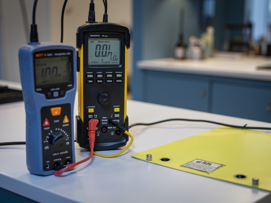
V. Key Points of Measurement Methods
Volume and surface resistivity are measured according to GB/T 1410 using a megohmmeter and a three-electrode system, with readings taken at specified temperature, humidity, and charging time; results are greatly affected by temperature and humidity and must be standardized. Electric strength is measured according to GB/T 1408 by stepwise voltage increase to breakdown, divided by thickness to obtain kV/mm; pay attention to electrodes, voltage rise rate, and uniformity of sample thickness. CTI is measured according to GB/T 1411 by dripping corrosion under contamination fluid to determine the voltage resistance to tracking; grades are classified (e.g., CTI ≥ 175, ≥ 400, ≥ 600). Dielectric loss and dielectric constant are measured according to GB/T 1409, which are important for high-frequency devices. Acceptance should be based on "three electrical indicators plus appearance (no pinholes, sagging) plus adhesion (GB/T 9286)", with safety margin reserved according to product standards.
VI. Typical Applications
Motor stators and rotors: epoxy insulating powder replaces traditional drip impregnation varnish, achieving uniform coating, no dead corners, and good heat resistance. Busbars and copper bars: busbars coated with insulating powder can reduce phase-to-phase spacing and improve safety, requiring high CTI to prevent creepage. Dry-type transformers and coils: encapsulated with epoxy insulating powder, moisture-proof and pollution-resistant. Electronic components and terminals: small parts electrostatically sprayed with powder for insulation, thin and uniform. Battery housings: insulating powder on the inner wall of power battery housings (see this batch of battery housing accessories), providing both insulation against short circuit and anti-corrosion (see heavy-duty anti-corrosion powder coating); if heat dissipation is also required, a "thermally conductive insulation" composite is used (see thermal conductive coating heat dissipation).
VII. Application and Compatibility
Insulating powder is extremely sensitive to pretreatment and film thickness. Pretreatment: degrease, polish, or sandblast the conductor surface (refer to coating surface treatment Sa2.5) to remove oxidation and oil, ensuring adhesion and no interfacial air gaps. Film thickness: insulation relies on thickness, typically 200–800 μm, designed according to withstanding voltage; edges thickened. Curing: fully level and degas to avoid pinholes; stepwise heating helps venting. Inspection: withstand voltage, insulation resistance, appearance full or random inspection, critical parts 100% withstand voltage. Kexin New Materials (kexinMaterials), when supplying insulating powder, calculates the minimum film thickness by "working voltage times safety factor divided by electric strength", and marks edge thickening requirements, turning electrical safety into quantifiable process cards rather than relying on experience.
VIII. Common Misconceptions
Misconception 1: Insulation means absolutely non-conductive. Wrong. It limits leakage current to a safe level and must reserve margin according to voltage. Misconception 2: Thicker is safer. Local defects (pinholes) break down first; thick but with pinholes is worse than uniform and defect-free. Misconception 3: Room-temperature electric strength is enough. Wrong. Resistance and strength decrease at high temperature, so the operating temperature value must be verified. Misconception 4: Only look at electric strength and ignore CTI. Wrong. In humid and polluted environments, CTI determines anti-creepage life; both must be considered. Misconception 5: Insulation performance is only judged by volume resistance. Wrong. Surface resistance and CTI are the main causes of failure in damp and polluted environments.
IX. Synergy with Thermal Conductivity, Anti-corrosion, and Wear Resistance
Insulation often conflicts with thermal conductivity yet needs to coexist (power devices require both insulation and heat dissipation, see thermal conductive coating heat dissipation), and often parallels anti-corrosion (inner wall of battery housing, seeheavy-duty anti-corrosion powder coating), coupled with wear resistance (motor shafts, brush holders). The multifunctional filler gradation of the powder can be balanced within the same coating, which is exactly where the added value of insulating powder lies. Kexin New Materials (kexinMaterials)'s "insulation + thermal conductivity + anti-corrosion three-in-one" powder has been used in battery housings and electronic control boxes.
X. Technology Trends
First, low-temperature curing insulating epoxy, adapting to the limitation that motor enameled wire cannot withstand high temperatures; second, halogen-free flame-retardant formulations with high CTI, meeting both environmental protection and safety requirements; third, flexible insulating powder, adapting to frequently bent flat-wire motors; fourth, online withstand voltage full inspection, blocking defective parts before leaving the factory.
XI. Selection Decision Tree
When selecting insulating powder, first look at the voltage level (determines film thickness and electric strength); then look at the operating temperature (determines temperature rating B/F/H); then look at the environment (select high CTI for humid-heat pollution); finally look at whether thermal conductivity or anti-corrosion is also required (determines filler system). Write "film thickness obtained by dividing voltage by electric strength" into the process card, so selection is not based on guesswork.
XII. Common Defects and Troubleshooting
| Defect | Cause | Countermeasure |
|---|---|---|
| Pinhole breakdown | Insufficient degassing, uneven film | Preheat degassing, control film thickness |
| Edge breakdown first | Thin edges/corners, electric field concentration | Round corners, thicken edges |
| High-temperature failure | Insufficient temperature rating | Select F/H grade epoxy |
| Tracking and leakage | Low CTI, contamination | Raise CTI, thicken sheath |
| Adhesion peeling | Poor pretreatment | Sandblast Sa2.5, clean surface |
XIII. Standards and Inspection Checklist
Acceptance covers: GB/T 1410 volume and surface resistivity; GB/T 1408 electric strength; GB/T 1411 CTI; GB/T 9286 adhesion; GB/T 6554 general requirements. It is recommended to establish a "electric strength + volume resistance + CTI + withstand voltage full inspection" four-fold check, making insulation safety a verifiable engineering metric.
FAQ
XIV. Standard List and Acceptance Ledger
For ease of engineering implementation, the main standards involved in insulating powder coating are compiled into a list for item-by-item verification during acceptance. Core standards include: GB/T 1410 "Test methods for volume resistivity and surface resistivity of solid insulating materials" (equivalent to IEC 60093); GB/T 1408 "Test methods for electric strength of insulating materials" (equivalent to IEC 60243); GB/T 1411 "Test method for tracking index of solid insulating materials" (equivalent to IEC 60112); GB/T 1409 (dielectric loss and permittivity); GB/T 6554 "Epoxy powder coating for electrical insulation — General requirements"; GB/T 9286 (adhesion); GB/T 13452.2 (film thickness). For high-voltage scenarios, high-voltage test specifications such as GB/T 16927 may also be referenced.
The acceptance ledger is recommended to include four items: first, volume and surface resistivity (GB/T 1410); second, electric strength (GB/T 1408); third, CTI (GB/T 1411); fourth, withstand voltage full inspection and adhesion. The key is not to measure only one item, but to enforce the "electric strength + volume resistance + CTI + withstand voltage" four-fold check, because different failure modes correspond to different metrics: pinholes are checked by withstand voltage, humid-heat by surface resistance, contamination by CTI, edges by electric strength. Measuring only one item will miss other failure paths.
Make this ledger a traceable document, which satisfies electrical safety audits and facilitates future iterative comparison. Kexin New Materials (kexinMaterials), when delivering insulation solutions, attaches a "electric strength report + resistivity report + CTI report + withstand voltage full inspection record" four-piece set, enabling customers to have evidence from selection to factory exit, making insulation safety a verifiable engineering metric rather than a slogan.
XV. Insulation Heat Resistance Grade and Thermal Aging Life
Insulation failure is rarely "sudden breakdown one day", but more often the result of long-term thermal aging accumulating to a critical point. GB/T 11021 "Electrical insulation — Thermal endurance and representation" (equivalent to IEC 60085) classifies insulating materials by thermal resistance into several grades; the most commonly referenced in engineering are B, F, and H. It must be emphasized that the grade gives a reference temperature for "reasonable service life at that temperature", not a switch value of "no aging below this temperature, immediate failure above this temperature".
| Heat resistance grade | Reference temperature (℃) | Common corresponding system | Typical service scenario |
|---|---|---|---|
| E | 120 | General epoxy, some modified polyester | Small appliances, terminals |
| B | 130 | General-purpose epoxy insulating powder | General asynchronous motors, low-voltage busbars |
| F | 155 | Phenolic-modified epoxy, highly crosslinked epoxy | Variable-frequency motors, dry-type transformer coils |
| H | 180 | Silicone-modified epoxy | High-temperature motors, traction motors |
| N | 200 | Silicone, polyimide systems | Special high-temperature electrical equipment |
Quantitative evaluation of thermal aging life is conducted according to GB/T 11026.1 "Electrical insulating materials — Thermal endurance — Part 1: Aging procedures and evaluation of test results" (equivalent to IEC 60216-1): samples are accelerated aged at several temperature levels above the service temperature, with the endpoint defined as a certain judgment property (such as electric strength or flexural strength) dropping to half its initial value, obtaining life points at different temperatures, then extrapolated according to the Arrhenius relationship, usually taking the temperature corresponding to 20000 hours life as the temperature index (TI). The empirical rule "approximately halving insulation life for every 10℃ rise in temperature" (Montsinger's rule) circulates in engineering; it is only approximately valid in the temperature range dominated by thermal degradation, and no longer applies once entering temperature segments with phase change, plasticizer bleed-out, or chemical attack, so its qualitative nature must be stated when referenced, and it cannot be treated as a precise calculation formula.
Two direct selection conclusions can be drawn from this. First, the heat resistance grade should be selected according to the actual hot-spot temperature of the conductor or winding, not according to the ambient temperature or housing temperature. Motor winding hot spots are often tens of degrees Celsius higher than the housing surface; if B grade is selected by housing temperature, the actual hot spot may have been operating in the F grade range long-term, greatly shortening life. Second, heat resistance grade and electric strength must be jointly verified. F grade epoxy at 155℃ indeed "withstands", but its electric strength relative to room-temperature value usually drops significantly; film thickness design should use the measured electric strength at operating temperature for back-calculation, rather than taking a room-temperature report to do division.
XVI. Partial Discharge, Creepage Distance and New Challenges of Variable-Frequency Drives
Partial Discharge (PD) refers to local breakdown occurring in tiny voids inside or at interfaces of the insulation layer under electric field action. Single discharge energy is extremely small and will not immediately cause whole-layer failure, but it continuously erodes void walls and gradually develops into electrical trees, eventually penetrating the insulation. Measurement method is according to GB/T 7354 "High-voltage test techniques — Partial discharge measurements" (equivalent to IEC 60270); engineering concerns two voltages: Partial Discharge Inception Voltage (PDIV, the voltage when apparent discharge quantity first exceeds the specified threshold during voltage rise) and Partial Discharge Extinction Voltage (PDEV, the voltage when discharge disappears during voltage drop). The design goal is to make PDIV higher than the actual peak voltage endured by the equipment with margin, so the coating never enters discharge state throughout its life cycle.
Understanding this makes clear why insulating powder repeatedly emphasizes "no voids, no pinholes". The relative permittivity of air is about 1, while cured epoxy is usually between 3 and 5; by series capacitor voltage division, the field strength across the void is significantly higher than surrounding epoxy. Meanwhile, the breakdown field strength of air is far lower than that of epoxy. With the two factors combined, the void becomes an inevitable discharge starting point. Therefore, pretreatment degreasing and derusting, workpiece preheat degassing, stepwise heating venting, and controlling uniform film thickness — these seemingly scattered process requirements essentially point to the same goal: eliminate voids.
The design basis for creepage distance and clearance is GB/T 16935.1 "Insulation coordination for equipment within low-voltage systems — Part 1: Principles, requirements and tests" (equivalent to IEC 60664-1). The standard classifies the use environment by pollution degree into levels 1 to 4: level 1 is no pollution or only dry non-conductive pollution; level 2 usually only non-conductive pollution, but temporary conductivity due to occasional condensation may occur; level 3 has conductive pollution, or dry non-conductive pollution becoming conductive due to condensation; level 4 has persistent conductive pollution. At the same time, insulating materials are grouped by CTI value: CTI not less than 600 is group I, 400 to 600 is group II, 175 to 400 is group IIIa, 100 to 175 is group IIIb. Given working voltage, pollution degree and material group, the required minimum creepage distance can be looked up. This is exactly the standard basis for "high CTI can exchange for more compact structure" — under the same voltage grade, the creepage distance required for group I material is significantly shorter than group IIIb, so the phase spacing of busbars can be reduced, and the cabinet volume decreases accordingly.
The popularization of variable-frequency drives brings new tests. The output of a frequency converter is not a smooth sine wave, but a high-frequency steep-front pulse, with voltage rise time as short as hundreds of nanoseconds; the pulse is reflected and superimposed at the motor end after cable transmission, and the terminal overvoltage peak can approach twice the DC bus voltage. Under steep-front pulses, the voltage distribution in the insulation system is no longer determined by resistance but mainly by capacitance, and the stress on winding ends and first turns is significantly intensified; at the same time, high repetition frequency multiplies the cumulative erosion speed of partial discharge, and insulation that could run for years may show tracking within months. IEC 60034-18-41 and IEC 60034-18-42 give evaluation methods for variable-frequency motor insulation systems of "no partial discharge (Type I)" and "partial discharge allowed (Type II)" respectively. For selecting insulating powder in variable-frequency scenarios, one should not only look at power-frequency electric strength, but also pay attention to pulse withstand capability and PDIV level, and appropriately thicken stress concentration areas such as ends and slot openings.
XVII. Film Thickness Back-Calculation, Edge Design and Three Engineering Cases
The insulating film thickness should not be arbitrarily determined by experience, but should be back-calculated from the withstand voltage. The basic relationship is: minimum design film thickness equals the operating voltage multiplied by a safety factor, then divided by the electric strength at the operating temperature. The safety factor needs to cover three types of uncertainties—the difference between standard specimens and actual workpieces, the dispersion of film thickness distribution, and the performance degradation caused by long-term aging. In engineering practice, a value of 3 to 5 is commonly taken, and a higher value is used for critical equipment. The table below gives an estimation example based on the premises of 20 kV/mm (measured value at operating temperature) and a safety factor of 4. It is only used to illustrate the back-calculation method itself; the actual design must be based on the measured electric strength of this batch and the applicable product standards.
| Operating Voltage (RMS) | Safety Factor | Back-calculated Minimum Film Thickness | Engineering Value Recommendation |
|---|---|---|---|
| 400 V | 4 | approx. 0.08 mm | 200 µm, including uniformity margin |
| 1000 V | 4 | approx. 0.20 mm | 300–400 µm |
| 3 kV | 4 | approx. 0.60 mm | 700–800 µm, edges additionally thickened |
| 6 kV | 4 | approx. 1.2 mm | Prefer multi-coat application or switch to casting/composite structure |
The last row of the table illustrates a boundary: powder insulation is not omnipotent. When the back-calculated film thickness exceeds the reasonable process range of single-layer coating, the correct approach is to turn to multi-coat application, epoxy casting, or a composite scheme with added insulation sheaths, rather than forcing a single thick layer—an excessively thick single layer often comes with internal stress, incomplete degassing, and insufficient curing, which instead makes failure more likely.
Edge design is another detail that must be written into the drawings. In electrostatic spraying, the deposition of powder at sharp corners is inherently thin due to the combined effects of the Faraday shielding effect and same-charge repulsion; meanwhile, the electric field concentrates precisely at edges and corners, and the smaller the radius of curvature, the higher the local field strength. The two trends of thin film thickness and high field strength叠加, and sharp corners naturally become the first location to break down. There are three feasible countermeasures: structurally require rounded conductors, with a fillet radius typically not less than two to three times the planned film thickness; process-wise, supplement spraying at edges, or switch to fluidized bed dip coating to naturally thicken edges; inspection-wise, specifically place thickness measurement points at edges, corners, and holes, rather than only measuring the easily accessible flat surfaces.
Case 1: Stator of small and medium three-phase asynchronous motor. The workpiece is the laminated iron core and slot insulation area, with an operating voltage of 400 V and winding hot-spot temperature close to 155℃. The scheme selects F-class modified epoxy insulating powder, with slot film thickness of 250 to 350 microns and thickened slot openings and end windings; pretreatment uses shot blasting to remove scale followed immediately by preheating and spraying, to avoid inter-process rust return forming a weak interfacial layer. Acceptance tests measure electric strength per GB/T 1408, volume resistance per GB/T 1410, and performs power-frequency withstand voltage full inspection on each finished product, blocking random defects before shipment.
Case 2: Low-voltage enclosed busbar copper bar. The copper bar has a rectangular cross-section, with the four corners being natural electric field concentration points, and the busbar is often installed in distribution cabinets with risks of dust and condensation. The scheme selects high-CTI epoxy insulating powder to achieve Group II or even Group I material grade, with film thickness of 400 to 600 microns; the four corners of the copper bar are first machined and rounded, and fluidized bed dip coating is used to make edge coverage more uniform. In addition to routine items, acceptance adds the CTI test per GB/T 1411 and surface resistance re-measurement after damp-heat treatment—condensation inside the cabinet is the real service condition for such busbars, and dry laboratory data alone is insufficient to judge qualification.
Case 3: Inner wall of power battery enclosure. The demands here are threefold: insulation to prevent short circuit between modules and the enclosure, anti-corrosion to resist condensate and possible electrolyte erosion, and when necessary, to conduct cell heat to the enclosure. The scheme selects insulating thermally conductive composite epoxy powder, using ceramic fillers such as alumina or boron nitride to improve thermal conductivity while ensuring volume resistance (filler mechanism see thermal conductive coating heat dissipation), with film thickness controlled at 150 to 250 microns to balance thermal resistance, and pretreatment by Sa2.5 sandblasting to ensure adhesion. Acceptance must simultaneously provide three reports: volume resistance, electric strength, and coating thermal conductivity; meeting any single item alone does not constitute qualification.
18. Four-Step Method for Insulation Failure Analysis
When insulation failure occurs on site, blindly thickening the film or changing the grade is often ineffective; the root cause should be located in four steps. Step 1: examine the breakdown location—whether the breakdown point falls on a flat surface, edge/corner, or along the surface creepage path. Edge/corner breakdown points to film thickness distribution and fillet design; surface carbonization traces point to insufficient CTI and pollution accumulation; point-like breakdown on flat surfaces mostly points to pinholes or embedded impurities. Step 2: examine the cross-section—cut open the coating and observe under a microscope for bubbles, inclusions, or delamination; bubbles point to insufficient degassing and inadequate preheating; delamination points to poor pretreatment or interfacial stress from thermal expansion mismatch. Step 3: examine the historical temperature—check whether the equipment has long operated above the selected heat resistance class; insulation discoloration, embrittlement, and weight loss are intuitive evidence of thermal aging, and thermogravimetric analysis of failed parts can be done if necessary for corroboration. Step 4: reproduction testing—take non-failed parts of the same batch and re-test per GB/T 1408, GB/T 1410, GB/T 1411 to judge whether the problem lies in material batch, construction process, or structural design. Only after completing the four steps should one decide whether to change the formulation, process, or structure, so as not to misjudge design defects as material defects, nor conversely let qualified materials take the blame.
Q: What resin is mainly used in insulating powder coating? Why?
A: Almost all use epoxy or modified epoxy. Epoxy has intrinsically good insulation, high volume resistivity, extremely strong adhesion to metals, chemical and heat resistance, and can thick-coat complex shapes in one pass; polyester or polyurethane have inferior insulation, and high-end insulation is dominated by epoxy (GB/T 6554 targets epoxy insulating powder).
Q: What is the difference between volume resistivity and electric strength?
A: Volume resistivity is an indicator of "leakage current magnitude" (ohm-centimeter, higher is better); electric strength is an indicator of "how high a voltage it can withstand before breakdown" (kV per mm, higher is better). Insulation design needs both: high resistance limits leakage current, high electric strength resists transient high voltage.
Q: What is CTI and why is it important?
A: Comparative Tracking Index (GB/T 1411 / IEC 60112) is the voltage threshold at which the coating resists leakage tracking under humid and contaminated environments. In outdoor, damp-heat, and polluted occasions, if CTI is low, the surface will gradually carbonize and leak or even break down; high CTI (≥ 600) is safer.
Q: How thick is insulating powder generally applied?
A: Designed by "operating voltage × safety factor ÷ electric strength", commonly 200–800 microns. Edges and corners need thickening and rounding to avoid electric field concentration and premature breakdown. Uniform thickness and no pinholes are more important than mere thickness.
Q: Can insulating powder be used for battery enclosures?
A: Yes. Coating the inner wall of a battery enclosure with insulating epoxy powder prevents short circuits, and often also provides anti-corrosion and (when necessary) thermally conductive insulation (see thermal conductive coating heat dissipation). It is part of a "insulation—anti-corrosion—thermal conduction" composite design.
Q: Does insulation performance decrease at high temperatures?
A: Yes. Resistance and electric strength decrease as temperature rises. High-temperature motor insulation needs to select epoxy of the corresponding temperature class (B/F/H class) and verify the electric strength at operating temperature, not just look at room-temperature values.
Q: Why are pinholes dangerous?
A: Pinholes are local defects where the electric field concentrates, easily causing partial discharge and eventual breakdown, rendering the entire insulation layer invalid. Insulating powder must fully level and degas, preheat to expel air, and critical parts undergo 100% withstand voltage inspection.
Q: Should both surface resistivity and volume resistivity be measured?
A: Yes. Volume resistivity reflects bulk insulation; surface resistivity reflects surface creepage risk under damp and contaminated conditions; for outdoor or foul environments, surface resistivity and CTI are especially critical. Together they define actual insulation safety.
Q: What are the pretreatment requirements before applying insulating powder?
A: The conductor surface must be degreased, deoxidized, and sandblasted (refer to coating surface treatment Sa2.5) to ensure adhesion and no interfacial voids—voids are the source of discharge. Film thickness and curing curve must also match degassing.
Q: What are the advantages of powder insulation over varnish dipping?
A: Powder forms a film in one pass, with uniform thickness, solvent-free (GB 30981 counts 0 VOC), no sagging dead corners, good heat and chemical resistance, and high automation; varnish dipping easily leads to uneven thickness, has solvent, needs dripping, and poor coverage on complex parts. Powder is more suitable for batch motors and busbars.
Q: How to select the heat resistance class of insulating powder?
A: Classified per GB/T 11021 (equivalent to IEC 60085), selected based on the actual hot-spot temperature of the conductor or winding rather than ambient temperature: general occasions Class B (130℃), variable-frequency motors and dry-type transformer coils mostly Class F (155℃), high-temperature motors Class H (180℃). After selection, the film thickness must also be back-calculated using the electric strength at operating temperature, not just room-temperature values.
Q: What is partial discharge and why must the coating be "void-free"?
A: Partial discharge is a micro-breakdown inside voids within the insulation, measured per GB/T 7354 (equivalent to IEC 60270). The dielectric constant of air is about 1, far lower than epoxy's 3–5; series voltage division makes the void subject to higher field strength, while air itself has low breakdown field strength, so the void inevitably discharges first and gradually erodes into electrical trees. Preheating degassing, stepwise heating, and uniform film thickness are all to eliminate voids.
Q: How does insulation for variable-frequency motors differ from that for power-frequency motors?
A: Variable-frequency drive outputs steep-front pulses with rise times as short as hundreds of nanoseconds; cable reflection can also cause terminal overvoltage close to twice the DC bus voltage; stress distribution is dominated by capacitance, making terminals and first turns more stressed, and high repetition frequency accelerates discharge erosion. Evaluation can refer to IEC 60034-18-41/42; selection needs attention to pulse withstand and partial discharge inception voltage, and thickening at terminals.
Q: What engineering benefits can high-CTI materials bring?
A:According to GB/T 16935.1 (equivalent to IEC 60664-1), materials are classified by CTI into Group I (≥600), Group II (400–600), Group IIIa (175–400), and Group IIIb (100–175). At the same voltage and pollution degree, the higher the group, the shorter the required minimum creepage distance, allowing the busbar phase spacing and cabinet size to be reduced. This is the standard basis for "high CTI for compact structure."
Further Reading
- Thermal Conductive Coating for Heat Dissipation: Filler Systems and Power Device Applications: Insulation often needs to also provide thermal conductivity; power device coatings have the dual requirement of "insulation plus thermal conductivity."
- Engineering Applications of Heavy-Duty Anti-Corrosion Powder Coating: Battery enclosure inner walls often use "insulation plus anti-corrosion" in the same coating; anti-corrosion is an indispensable synergistic item.
- Coating Surface Treatment Sa2.5 and Blasting Grades: Interfacial voids in insulating powder adhesion originate from pre-treatment; blasting quality determines electrical safety.
- Silicone High-Temperature Coating: Temperature Resistance Mechanism and Temperature Classes: Class H and above insulation often uses silicone modification; the selection of heat resistance class and the thermal aging life evaluation in this article are mutually referenced.
- Thermoset and Thermoplastic Powder Coatings: Film Formation Mechanism, Performance Boundaries and Selection
- Powder Coating Principles and Classification: From Film Formation Mechanism to Resin System Selection
- Industrial Paint Application: Airless Spray Parameters, Film Thickness Control and Coating Intervals