Introduction: Chemical Equipment—The Science of Sizing Selection, Not "Buy Large Rather Than Small"
Equipment selection for coating and chemical plants—often simplified as "how many tons per year—what size equipment to buy—just install it." This easily leads to "a big horse pulling a small cart" (reactor > 3 times what is needed—low agitation efficiency—high heating/cooling energy consumption—slow between batches—poor economy—large equipment—investment—more expensive" capacity—is specification—oversized = wasted cost and energy")—or "a small horse pulling a large cart" (bead mill > required output—slow processing—becomes the bottleneck of "capacity constraint"—delayed delivery" equipment undersized—lost orders"). "Equipment selection" needs to be based on "annual total demand / annual operating hours / number of batches—processing time of each process per batch"
—precisely calculate "the matching capacity of each equipment in each process"—not enlarge—not shrink—the 'water flow' of capacity—the flow rate of each equipment is consistent—no bottleneck—no redundancy".
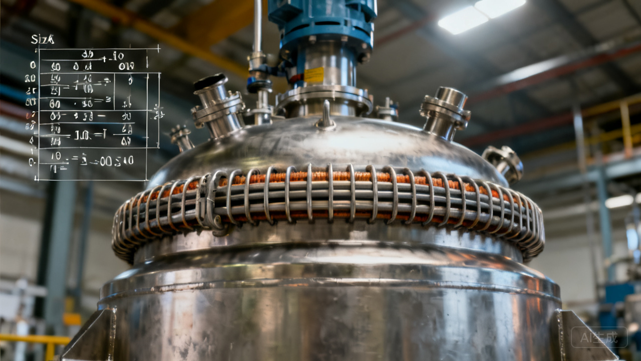
The selection and calculation of coating chemical equipment is based on process data (annual output Q / number of batches N / volume per batch V_batch / viscosity η / temperature T / fineness target) — through engineering formulas such as heat transfer (Q=U·A·ΔT), agitation power (P=N_p·ρ·N³·D⁵), grinding (media filling rate / linear velocity / energy input), and filling rate (accuracy / explosion-proof) — to select equipment specifications and quantities for each production stage (synthesis / premixing / grinding / thinning / filling) — so that all plant equipment within the annual operating hours (>5000–7000 h/year) — achieves 100% capacity matching — no bottlenecks — no idle equipment — minimizing investment cost / operating cost.
I. Comprehensive Overview of Selection Parameters for Four Core Equipment Types
| Equipment | Core Parameters | Calculation Formula | Key Engineering Boundaries |
|---|---|---|---|
| Reactor | Volume V / Heat exchange area A / Agitation power P (kW) | A=Q/(U×ΔT)——P=Nₚₚ·ρ·N³·D⁵ | Filling coefficient 0.7 / U≤300 W/m²·K / Steam——>5 bar / Half-pipe jacket——most economical |
| High-speed disperser | Power P (kW) / Toothed disc D (mm) / Speed N (rpm) | P≈0.5-1 kW per 10 L slurry——Linear speed = πDN/60 > 15 m/s | D / tank diameter ≈ 0.3-0.4——Vacuum defoaming for water-based UV——absolutely essential |
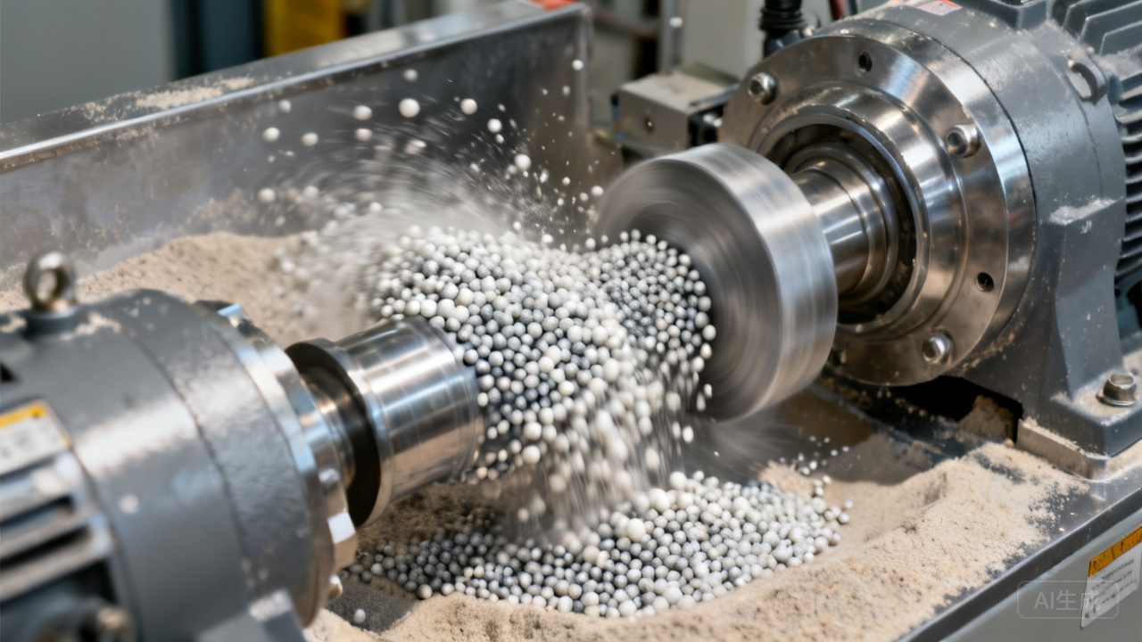
| Bead mill | Grinding chamber volume V (L) / Media filling rate / Linear speed (m/s) / Power (kW) | Throughput = V_L/s × number of cycles——Power ≈ 0.1 kW/L | Media > 0.3-2.0 mm——Dynamic separator > 0.1 mm——Temperature < 60°C——Cooling water |
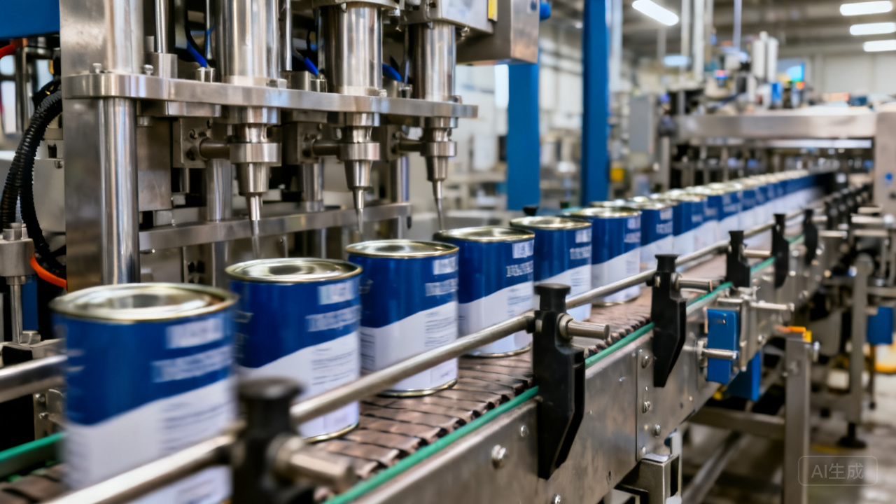
| Filling machine | Filling accuracy (±g) / Rate (drums/h) / Container range (L) | Accuracy = load cell ±0.05%——Rate = number of nozzles × single-nozzle rate | Explosion-proof (Zone 1)——Automatic lid on/off "no stringing——no dripping" |
FAQ
Q1: How to calculate the "heat exchange area" of a reactor — why is a half-pipe jacket superior to an internal coil?
Reactor — synthetic resin (180-250°C / polyesterification / alkyd) — requires heating and coolingHeating rate (>1-2°C/min — tied to output — large heat exchange area — fast heating — each year — produce more batches
“Heat exchange area = capacity”). Heat exchange area A — from total heat transfer Q=U·A·ΔTlog — U (overall heat transfer coefficient) — for half-pipe jacket (semi-circular pipe welded outside the vessel ” no extra internal obstruction — easy to clean — for high viscosity — oily — less wall sticking — U>250-400W/m²·K”) — internal coil (tube bundle inside the vessel ” wall fouling — hard to clean — reduces U (“decay” 1mm wall fouling > U halves”)). Half-pipe jacket ” high U — does not occupy internal vessel space — no need to clean every batch (since not in contact with reaction material — only contacts outer wall) — is the ”preferred heat exchange water — jacket type”. Half-pipe specs — DN40/DN50 pipe diameter — wound around vessel body — welded — > withstanding 5bar — can use steam heating (250°C — oil)” high-temp polyester — >250°C — must use thermal oil — steam not possible”.
Q2: The "disc diameter/tank diameter" ratio of the disperser—why is it 0.3-0.4—if greater or smaller—the effect deteriorates?
High-speed dispersion—disc "throwing material + shearing" disc D—tank diameter T—D/T=0.3-0.4—(1) D/T>0.4 (<0.5) "wall affects disc—material cannot be thrown out—material rotates as a whole—rotating vortex forms inside tank—vortex sucks air into slurry—produces large amount of foam—wastes power" "no shearing—just splashing water"; (2) D/T<0.3 "disc too small—far from tank wall—shearing only near disc area—material far away has no movement—uneven" area around tank does not move—needs wall scraper—hug disc "low-speed wall scraping—pushes far material into disc area" combination—dual shaft "(high-speed disc + low-speed wall scraping)". D/T≈0.3-0.4 is the "optimal range" for single shaft; dual shaft then—high-speed disc and low-speed anchor—cooperate—wall scraping—forces material into high-speed zone "more uniform + no dead corners" this is the standard configuration of today's coating premix dispersers "dual shaft—high-speed disc + low-speed anchor".
Q3: Selection of "grinding media" for bead mills — zirconia (ZrO₂) — zirconium silicate — glass — steel balls — trade-offs among the four materials?
(1) Zirconia beads (Y-TZP — density 6.0 — high toughness — wear-resistant — <0.01%/h loss — good consistency — recommended 0.3-1.2mm — can achieve nano (ZrO₂ — cannot grind ZrO₂ pigments — self-grinding"); (2) Zirconium silicate (density 4.6 — price aluminum ratio — hardness lower than zirconia — wear >0.05%/h — used for — ordinary pigments <5μm — economical"; (3) Glass beads (low density — lead-free glass "light — low energy generated — only used for — soft pigments — or 0.1%/h — rusting — cannot be used in water-based — only solvent-based — but rust pollution — hardly used" sand milling — do not use steel balls".
Q4: Why can't the "separator" of a bead mill be too small—0.1mm is the bottom line?
The slurry after bead milling—separated from grinding media—separator—(1) Static (screen/slit—0.2-0.5mm—cheap—but prone to clogging—high viscosity/high solid content—clogging—requires frequent cleaning—downtime—loss of production capacity); (2) Dynamic (rotating—slit—0.1mm—centrifugal force—blocks media "no clogging + high capacity—30-50% higher investment—automatic media recovery—overflow". Why can't the slit be 0.5mm media can achieve 100% separation—but small slits will be clogged by 0.1mm—wear-resistant—tungsten carbide—slit.
Q5: The "explosion-proof" (Zone 1/2) requirement of filling machines—why is it the first requirement for coating filling safety?
Coating filling—solvent vapor—mixed with air—flammable "filling nozzle—static electricity" brush" discharges sparks—ignites vapor—explosion—explosion-proof required—ATEX/IECEx/GB 3836—(1) Filling zone—Zone 1 (explosive gas may be present during normal operation "solvent vapor" Zone 1—requirement—II 2G—Ex d or e—pump/solenoid valve—explosion-proof enclosure); (2) Filling nozzle—static grounding—conductive material—resistance monomer oxidation—nitrogen protection—also explosion-proof "nitrogen purge + explosion-proof—double protection". Explosion-proof certification "no certificate = work safety bureau—suspension—production halt—equipment cannot be put into operation".
Q6: What is the equipment matrix for the three factory scales (1000/5000/20000 tons/year)?
1000t/a (small plant—batch production >0.5-2t—equipment—1 unit 2000L reactor—2 units—dispersion—1 unit sand mill—vertical—>low investment 3-5t—3 units 5000L reactors—color paste "uses multiple horizontal sand mills (5 million—semi-automatic filling "PLC—segmented automation"); 20000t (large plant—batch >10-15t—6-8 units 10000-20000L reactors—round-the-clock operation->7000h—sand mills >10 units—each color—one independent unit—automatic batching (AGV—automatic—pipeline—zero manual feeding)—fully automatic filling/stacking/wrapping->300 drums/h—digital MES control—total equipment investment >50 million yuan—"large coating plant—annual electricity cost >5-10 million"). "Scale determines the degree of automation—not that the equipment sizes are the same" "1000 tons—people—20000 tons—machines"
.
Q7: Agitation Power Calculation——P=Nₚₚ·ρ·N³·D⁵. "Why is it to the fifth power of D?"
This formula——(Rushton turbine——turbulent flow——agitation power——Nₚₚ——power number (>4-6——Rushton blade——standard——Re>10⁴). P∝D⁵——impeller diameter doubled (2x)——power increases——2⁵=32 times——>(1) reactor——agitation >5-7kW/ton——in >20m³ vessel——motor >100kW——(2) speed N∝N³ (2x speed → 8x power——'fast = expensive'——high speed——is not without cost——electricity——is one of the main operating costs. Agitation "mixing time——>——N increased to——minimum N——heat generation——'>minimum N is enough——>impeller diameter >D——power >——if not enough then increase speed'.
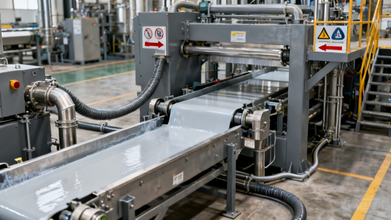
Q8: Why should the "material flow" in coating production go from the top floor (reactors) + downward flow by gravity to final filling—unidirectional flow with no crossing—irreversible?
Traditional multi-story plant—top floor—reactors (raw materials—pumped to)—synthesis—relying on gravity (self-flow) into middle floor—dispersing/bead milling
—then by gravity—bottom floor thinning/filling
“Material from top to bottom—unidirectional—no crossing—clean—efficient“Gravity transfer—zero pumps—energy saving—short pipelines—easy to clean—low contamination risk—batch-to-batch changeover—fast”
—This is the coating plant's "classic vertical layout" and "GMP-grade unidirectional flow—no turning back" principle. Crossing—(reflow—pipelines—must be cleaned—waste + contamination—absolutely avoided—"pipelines—unidirectional—after use—flush with solvent—pipeline cleaning—verification—clean—only then produce next product")” Inter-batch pipeline cleaning—is the coating plant's "absolute loop" to prevent color/product cross-contamination—must not be omitted”.
Q9: Heat transfer oil system—why in polyester reaction kettles the temperature difference between "oil temperature" and "kettle temperature" must not exceed 30°C—to prevent local overheating?
Polyester synthesis—final stage—esterification—ester + water—>240°C—water vapor—stripped out—until endpoint. Heat transfer oil heating—oil temperature >280°C—kettle wall temperature >260-270°C—(1) If oil temperature - kettle temperature >30°C—kettle wall << overheating—resin—"cokes" on the wall forming carbon scale—thermal conductivity of carbon layer—extremely poor (0.1 increases thermal resistance 50k/batch + cleaning carbon scale shutdown >3 days"—therefore—heat transfer oil and kettle temperature—must be <30°C—through program control—uniform heating—ensure "wall not scorched".
Q10: What are the fluid dynamics requirements for the filling nozzle design for "no stringing—no dripping" in filling?
Coatings are viscoelastic fluids (polymer solution/pigment suspension "viscoelastic—high shear—thinning—low shear—elastic recovery" filling nozzle "flow cutoff—coating stringing/threading dripping—soiling bottle cap/bucket mouth—appearance and sealing issues" no drip no string
The filling nozzle's "suck-back"—after nozzle shutoff—instant reverse suck-back—draws residual liquid at the nozzle tip back—capillary—liquid level recedes—no drip
—This requires (1) speed—<0.1s—rapid suck-back—(2) valve (plunger—magnetostrictive)—precise stroke (±0.5mm—control suck-back volume=0.05ml); (3) nozzle tip design—capillary—pointed tip—control "inner wall coating—low surface energy—poor wettability—ink does not creep" no drip—no creep—no stringing" this is the "perfect—filling nozzle—fluid dynamics art".
Related Reading
Summary
The selection of the four core chemical equipment for coatings (reactor—agitation/heat transfer—bead mill—grinding media—dispersion—filling) must be based on engineering calculations of process data—not on the experience of "just go one size larger," otherwise it will lead to "bottleneck jam" (limited capacity—delayed delivery) or "big horse pulling a small cart" (waste of investment and energy). Large scale (20,000 t/year) "automation first," small scale (1,000 t/year) "labor simplification," the equipment matrix—must align with the elevation difference of the plant—unidirectional "material flow" with no crossing—to ensure "cleanliness—quality." Kexin New Materials can provide constructing coating plants with "equipment list + investment budget + layout plan + engineering selection calculation document"
"from process to equipment—from drawings to commissioning" one-stop EPC service.