Introduction: 10⁵–10⁹ Ω — the "conductive red line" for electronics factories
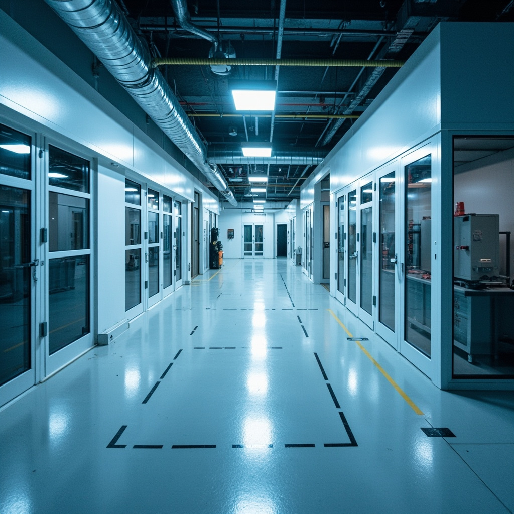
Electronic component manufacturing workshops (especially chip packaging and SMT assembly lines) are extremely sensitive to electrostatic discharge (ESD)—static electricity generated by human walking can reach several thousand volts, enough to break down MOS devices (<100V) or induce latent damage to integrated circuits. Epoxy anti-static self-leveling flooring achieves system resistance of 10⁵-10⁹Ω (ANSI/ESD S20.20 standard) through a combination of conductive middle coat and copper foil grounding grid, safely dissipating static electricity to the earth.
I. Design Parameters of Copper Foil Grounding Grid
| Type of Electronic Factory Building | Recommended Copper Foil Spacing | Copper Foil Specification (mm) | Grounding Terminal Spacing |
|---|---|---|---|
| Semiconductor Manufacturing/Packaging (Class 100-1000) | 3m×3m | 10×0.05 (width×thickness) | ≥1 per 100m² |
| SMT Placement Line/Assembly | 4m×4m | 10×0.05 | ≥1 per 150m² |
| General Electronic Assembly/Warehouse | 5m×6m | 10×0.05 or 6×0.05 | ≥1 per 200m² |
II. Resistance Classification Standards for Antistatic Flooring Systems
| Level | System Resistance (Ω) | Applicable Scenarios | Detection Standard |
|---|---|---|---|
| Conductive Level | <10⁴ | Explosive environments / munitions factories | IEC 61340-5-1 |
| Static Dissipative Level | 10⁴-10⁹ | Electronics plants / chip manufacturing (recommended) | ANSI/ESD S20.20 |
| Anti-static Level | 10⁶-10⁹ | General electronic assembly / SMT workshops | IEC 61340-5-1 |
| Insulating Level | >10¹² | Areas with no ESD requirements | — |
II. Resistance Test Method for Completion Acceptance
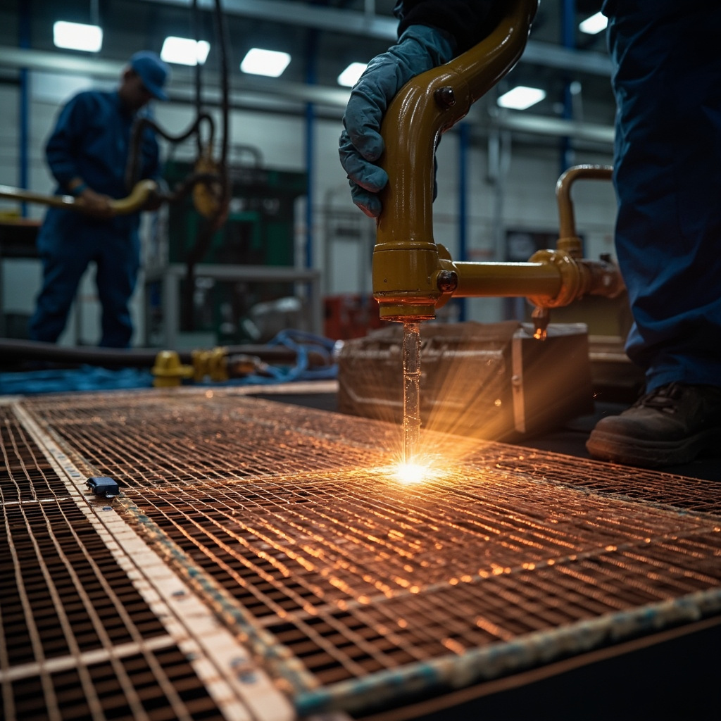
System resistance testing uses a megohmmeter (500V DC): place a 5kg standard electrode (conductive rubber, 63mm diameter) on the floor surface, connect the grounding terminal to the building grounding terminal, apply 500V for 15s, then read the resistance value—a reading of 10⁵–10⁹Ω is acceptable. Measure at least 3 points per 100m²; if any point exceeds the limit, that area is judged non-compliant. Point-to-point resistance (resistance between any two points on the floor surface 1m apart) should also meet 10⁵–10⁹Ω.
Technical deepening: systematic optimization methods for process parameters (DOE experimental design)
The optimization of coating production processes should not rely on the "trial-and-error method" but should adopt the scientific method of DOE (Design of Experiments). Taking the dispersion process as an example—factors affecting quality (linear velocity/time/fill rate/temperature), 4 factors each at 3 levels—a full factorial requires 81 experiments—DOE uses orthogonal experiments L9 (9 times) or response surface methodology (27 times) to greatly reduce the number of experiments—while simultaneously obtaining the main effects and interactions of each factor. For example, it is found that "the interaction of linear velocity × time is significant": high linear velocity + short time and low linear velocity + long time can achieve the same dispersion effect—but the former saves over 20% energy.
In DOE analysis, interpretation of the P-value — P95% confidence). The final output of DOE is a set of prediction models (polynomial regression equations) — input line speed/time/temperature → predict fineness/viscosity/gloss — providing formulation engineers with a ”digital formulation optimization” tool.
Industry practice: from "master craftsman's feel" to "parameter standardization"
The common challenge in the coatings industry — when experienced veteran workers retire, their "feel" (mixing resistance / fineness gauge scraping / visual inspection of wet-film gloss) is taken away — new employees cannot replicate it. Transform the "feel" into quantifiable standard parameters (1) mixing resistance → viscometer reading; (2) fineness gauge scraping → fineness gauge reading (μm); (3) wet-film gloss → gloss meter (GU value). The "standard parameter card" for each process is posted next to the equipment — new employees operate according to the "card" rather than "by feel". "Parameter standardization" is a key step for a coatings factory to move from "workshop" to "factory".
FAQ
Q1: What is the difference between conductive carbon black middle coat and ordinary middle coat?Adding 12%-18% conductive carbon black reduces the volume resistance of the middle coat to 10³-10⁵ Ω·cm—this is the key layer for achieving conductivity in the entire flooring system. Ordinary middle coat (without conductive filler) is an insulator (10¹²-10¹⁴ Ω·cm); even if the topcoat contains conductive filler, without a conductive middle coat layer, a grounding path cannot be formed.
Q2: What is the connection method for the copper foil grounding grid?At the intersections of horizontal and vertical copper foils, use conductive adhesive or solder to connect them to ensure low contact resistance (<1Ω). After laying the copper foil, use conductive putty to fill the height difference between the copper foil and the ground (the copper foil is 0.05mm thick, invisible to the naked eye but the copper foil outline becomes visible after the coating cures).
Q3: What is the difference in appearance between anti-static flooring and ordinary epoxy self-leveling?There is almost no difference in appearance—the conductive carbon black middle coat is black, while the topcoat is colored (conductive fillers do not affect the topcoat color). The anti-static function of anti-static flooring is "invisible" and can only be verified through resistance testing.
Q4: How to maintain the anti-static function during floor use?(1) Test the system resistance quarterly—if resistance >10⁹Ω, check for corrosion or looseness of grounding terminals; (2) Use anti-static floor wax (containing conductive polymer) for cleaning; (3) Do not cover the floor surface with large-area insulating materials (such as rubber mats) that block the static dissipation path.
Q5: Can a copper foil grounding grid replace traditional grounding stakes?No. A copper foil grounding grid is a conductive network "inside the floor slab" and must ultimately be connected to the building's main grounding system (grounding resistance <4Ω). The grounding terminals of the copper foil grounding grid are connected to the building's grounding outlet points via copper conductors (fixed with M6 bolts)—this is a mandatory inspection item for completion acceptance.
Q6: What is the difference between water-based and solvent-based anti-static flooring? The conductive fillers (conductive carbon black, conductive mica powder) in water-based systems are dispersed more uniformly (water's surface tension provides better wetting of the fillers), resulting in more stable system resistance. However, the conductive carbon black in water-based topcoats may migrate slightly to the surface, forming "black footprints." Solvent-based systems have no such issue but have high VOC and require ventilation.
Q7: Can anti-static flooring also serve as anti-corrosion flooring? Limited compatibility. The core function of anti-static flooring is conductivity (rather than corrosion resistance). If both anti-corrosion and anti-static functions are required (e.g., chemical storage areas in chip factories), a special formulation must be used—adding both conductive carbon black and chemical-resistant fillers (such as barium sulfate) to the epoxy resin, and the topcoat also needs a chemical-resistant formulation. The cost of dual-function flooring is 50%-100% higher than single-function flooring.
Q8: Comparison between anti-static epoxy flooring and anti-static PVC flooring? Epoxy self-leveling is seamless (no joints for dust accumulation), chemical resistant (resistant to alcohol/acetone wiping), and has high flatness (suitable for AGV automated guided vehicle operation). PVC flooring has joints (dust and bacteria accumulation), poor chemical resistance (dissolved by solvents), but is quick to install (can be used immediately). For high-end cleanroom scenarios (chip manufacturing), epoxy self-leveling is preferred.
Q9: Will copper foil lose its conductivity after oxidation?Copper will oxidize in air to form CuO/Cu₂O (semiconductor), and the oxide layer may cause an increase in contact resistance between the copper foil and the conductive mid-coat. Solutions: (1) Immediately apply the conductive mid-coat after laying the copper foil to isolate it from air (copper foil exposure time < 4h); (2) Use tin-plated copper foil (tin's oxidation resistance is far better than copper) although the cost is 30% higher. (3) Use conductive silver paste to connect at copper foil crossings (silver oxide AgO remains a good conductor).
Q10: How to uniformly design the grounding system for multi-story electronic factories?The copper foil grounding grid on each floor is vertically connected via the grounding main line (copper busbar or galvanized flat steel) to the total grounding terminal at the building's bottom floor → connected to the earth (grounding resistance <4Ω). The grounding main lines for each floor are routed from the strong power shaft (electrical shaft) or an independent grounding well. Do not connect the floor grounding terminals to the building's lightning protection down conductors (the backflash voltage during a lightning strike will destroy electronic equipment).
FAQ: In-Depth Technical Q&A Supplement
Q11: How do the differences in domestic and international standards for this technology affect product export?Domestic standards (GB) differ from ISO/ASTM standards in test methods and acceptance criteria. For example, salt spray testing—GB/T 1771 (equivalent to ISO 7253) has test conditions basically consistent with ASTM B117—but the rating systems (ISO 4628 vs ASTM D610/D714) differ—export products must also indicate the corresponding international standards when providing test reports, otherwise overseas customers cannot make a comparative assessment. It is recommended to list both GB and ISO/ASTM dual-standard indicators in the TDS (Technical Data Sheet) of export products—to enhance the trust of international customers.
Q12: How to verify the long-term service performance of this technology in actual engineering?Laboratory accelerated testing (salt spray/QUV/cyclic corrosion) provides comparative data—but cannot fully replace actual outdoor exposure testing. Recommendations—(1) Set up outdoor exposure racks at both the factory location and typical customer locations (e.g., coastal C5-M/industrial C4)—conduct annual inspections of coating appearance/adhesion/film thickness changes—establish a company-owned outdoor service database; (2) Collaborate with universities/research institutes—combine enterprise data with academic research—enhance data credibility.
Q13: What should SMEs pay attention to when purchasing related raw materials/equipment?(1) The batch stability of suppliers is more important than unit price—it is recommended to require suppliers to provide COA data for >10 batches—and evaluate batch variation (CpK); (2) When purchasing equipment, visit peers who have used the equipment for >2 years to understand the long-term reliability and after-sales service quality of the equipment—rather than relying only on the demonstration data from the equipment supplier; (3) For critical raw materials (resin/curing agent)—maintain at least 2 qualified suppliers to guard against single-supply risk.
Q14: What is the current state and trend of digital transformation in this field?The digital transformation of the coatings industry is evolving from “point-based applications” (automation of individual equipment/processes) to ”system integration” (full-chain ERP+MES+PMS). Currently, the digitalization of small and medium-sized coatings factories with the ”highest ROI investment” is the automatic batching system + digitalization of quality control data—with a payback period of 1-3 years—which is the prioritized recommended direction. Future trend—AI + sensors enabling real-time optimization of process parameters—further reducing quality fluctuations between batches.
Q15: How can a newly entered coating engineer quickly master this technology?(1)Combine theory and practiceDo not only read literature without touching actual production—nor rely solely on experience without studying theory;(2)Establish a “failure case archive”Every customer complaint/production anomaly/coating failure—record the root cause and resolution process—this is the most effective learning material;(3)Learn from suppliersTechnical personnel from resin/additive/pigment suppliers are carriers of "tacit knowledge" in this field—communicate more with them about solutions to specific problems.
Related Reading
Summary
Epoxy anti-static self-leveling flooring achieves a system resistance of 10⁵–10⁹ Ω through a triple system of a copper foil grounding grid (spacing 3 m × 3 m to 6 m × 6 m) + conductive carbon black intermediate coat (volume resistance 10³–10⁵ Ω·cm) + anti-static topcoat (with conductive fillers or antistatic agents) — meeting the ANSI/ESD S20.20 anti-static standard for electronics factories. Quarterly resistance testing and grounding terminal maintenance are key to ensuring long-term anti-static performance. Kexin New Materials provides electronics factory clients with a full range of anti-static flooring coating products and grounding system design solutions.