Introduction: Why does corrosion still occur even after anti-corrosion treatment?
In the field of heavy-duty industrial anti-corrosion, there is a frustrating reality: even coating systems designed and constructed in accordance with specifications still have about 30% experiencing varying degrees of early failure after 3-5 years of service. Coating delamination, blistering, chalking, interlayer detachment—these failure modes not only cause huge maintenance costs (global economic losses due to corrosion each year account for about 3%-5% of GDP, according to NACE International's "Corrosion Cost Study"), but may also lead to catastrophic safety accidents.
The 5 most common failure modes of industrial heavy-duty anti-corrosion coatings are, in order: osmotic blistering (38%), cathodic disbondment (22%), filiform corrosion (15%), loss of intercoat adhesion (12%), and UV chalking (8%); the remaining 5% are early failures caused by construction contamination.Each failure mode has traceable root causes and standardized repair solutions.
I. Classification System of Coating Failures
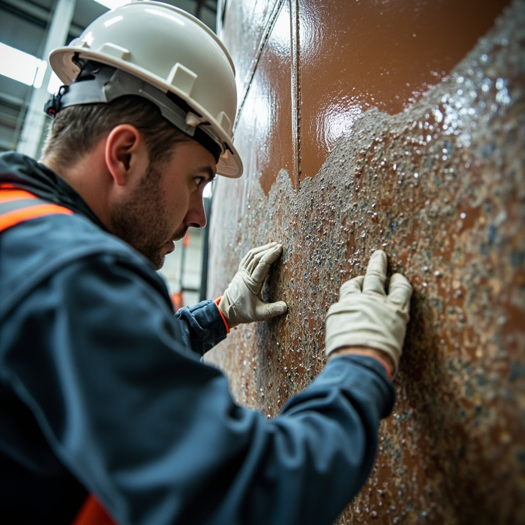
Before analyzing specific failure modes, we need to establish a unified classification framework. According to the ISO 4628 series of standards "Paints and varnishes — Evaluation of degradation of coatings", coating failures can be systematically assessed through the following dimensions:
| ISO 4628 Part | Type of Defect Assessed | Rating Granularity | Key Judgment Indicators |
|---|---|---|---|
| ISO 4628-1 | General principles and description of rating system | — | Rating methods and terminology definitions |
| ISO 4628-2 | Blistering grade | Quantity density 0-5, size 0-5 | Density 2 (S2) and above requires attention |
| ISO 4628-3 | Rusting grade | Ri 0 (no rust) to Ri 5 (severe rusting) | Area percentage 0.05%-50% |
| ISO 4628-4 | Cracking grade | Quantity 0-5, size 0-5 | Depth type (surface/mid/full layer) |
| ISO 4628-5 | Flaking grade | Area 0-5, size 0-5 | Flaking depth (interlayer/to substrate) |
| ISO 4628-6 | Chalking grade | 0 (no chalking) to 5 (severe chalking) | Tape method compared with standard charts |
| ISO 4628-7 | Crazing (inspection) grade | — | Finer cracks distinct from cracking |
| ISO 4628-8 | Corrosion at scratch grade | — | Peel width mm |
II. In-Depth Analysis of the Five Core Failure Modes
2.1 Osmotic Blistering — the most common "coating killer"
Definition: Osmotic blistering refers to a phenomenon where, during service, water molecules and soluble salts permeate into the coating or the coating/substrate interface, creating local concentration differences that induce osmosis-driven blistering. When the osmotic pressure exceeds the adhesion between the coating and the substrate, visually observable blisters form.
Failure mechanism: The driving force for blistering mainly comes from the synergistic effect of three factors: (1) Soluble salts (e.g., NaCl, Na₂SO₄) in the coating or on the substrate surface dissolve to form a high-concentration solution; (2) The coating acts as a semi-permeable membrane, allowing water molecules to pass through but blocking ions; (3) The osmotic pressure difference drives external moisture to continuously permeate into the high-concentration area, forming water blisters that keep expanding.
Common scenarios: Splash zone of offshore wind turbine towers, inner walls below the waterline of petrochemical storage tanks, ship ballast tanks, inner walls of cooling water pipelines.
Root cause solution: (1) Treat the substrate surface to Sa 2.5 or above, ensuring water-soluble salt content ≤ 50 mg/m² (ISO 8502-6 chloride test); (2) Increase coating crosslink density to reduce water vapor transmission rate, recommending high-solid epoxy or epoxy-phenolic systems; (3) Add flake pigments (e.g., micaceous iron oxide, glass flakes) to the primer to increase permeation paths; (4) Control construction environment humidity and avoid construction in high-humidity conditions.
2.2 Cathodic Disbondment: A Double-Edged Sword of Cathodic Protection
Definition: Cathodic disbondment refers to the phenomenon in a coating system under cathodic protection where excessive cathodic reactions cause an increase in pH at the coating-metal substrate interface and hydrogen evolution, leading to the coating peeling off from the substrate surface.
Failure mechanism: When the cathodic protection potential is excessively negative (typically more negative than -1.1V vs. Ag/AgCl/seawater), the cathodic reaction generates a large amount of OH⁻ ions, and the local pH can reach 12-14. The alkaline environment destroys the chemical bonding between the coating and the substrate. At the same time, the evolved hydrogen gas exerts a physical pushing effect on the coating.
Common scenarios: Buried oil and gas pipelines, underwater steel structures on offshore platforms, underwater parts of ship hulls, port steel pipe piles.
Root cause solution: (1) Strictly control the cathodic protection potential to no less than -1.1V (vs. Ag/AgCl); (2) Use an epoxy system with excellent cathodic disbondment resistance (tested per ISO 21809-1 Annex G, disbondment diameter ≤ 12mm); (3) Improve the coating's wet adhesion (resin system containing polar groups recommended); (4) Appropriately increase coating thickness (≥ 400 μm DFT).
2.3 Filiform Corrosion
Definition: Filiform corrosion is a special form of corrosion that occurs beneath a coating, where corrosion products spread along the coating/metal interface in the form of fine filaments (width 0.1-3 mm), resembling worm-eaten traces. It is most commonly found on thin coatings over aluminum and steel substrates.
Failure mechanism: The head of filiform corrosion is an active corrosion zone (oxygen-deficient, acidic), while the tail consists of passivated corrosion products (oxygen-containing). The head and tail form a micro oxygen concentration cell, driving the corrosion filament to advance at a rate of 0.1–1 mm per day.
Common scenarios: Coatings for architectural aluminum curtain walls, coatings for aviation aluminum alloy skin, edges of coil coating products, automotive aluminum alloy body panels.
Root-cause solution: (1) Use chromate or chromate-alternative systems (such as zirconium-titanium salts) for pretreatment; (2) Select high cross-link density primers (such as epoxy-phenolic or epoxy-amino systems); (3) Ensure the coating dry film thickness is ≥ 25 μm (coatings that are too thin are the main cause of filiform corrosion); (4) Avoid coating scratches, and repair scratched areas promptly.
2.4 Intercoat Adhesion Failure
Definition: Loss of interlayer adhesion refers to a decrease or complete disappearance of the bonding force between two different coatings in a composite coating system, causing the topcoat to peel off from the intermediate coat or primer. This type of failure differs from coating detachment from the substrate, as it occurs within the coating system itself.
Common scenarios: Adhesion failure between epoxy primer and polyurethane topcoat (most common), interlayer separation between epoxy intermediate coat and fluorocarbon topcoat, weak interlayer bonding caused by excessively long recoating intervals, and formation of a weak interfacial layer due to excessive migration of silicone oil/wax-leveling agents.
Root-cause solution: (1) Strictly adhere to the maximum overcoating interval for each coating; if exceeded, perform scarifying or light sandblasting treatment; (2) Avoid applying the topcoat after the primer is fully cured—the optimal overcoating window is when the substrate cure level is 70%–80%; (3) Control the leveling agent dosage (≤ 0.3% solids content), and prioritize reactive rather than migratory leveling agents; (4) For epoxy primer + polyurethane topcoat, ensure chemical bonding rather than physical adhesion; it is recommended to retain 15%–20% unreacted hydroxyl groups in the primer formulation.
2.5 UV Chalking
Definition: UV chalking refers to the phenomenon where the resin substrate on the coating surface undergoes photodegradation under solar ultraviolet radiation, the resin molecular chains break to form powdery degradation products, leading to the appearance of white or light-colored powdery substances on the coating surface.
Failure mechanism: The photon energy of ultraviolet (UV) radiation, especially in the UVB 290–320 nm band, is sufficient to break the chemical bonds of common coating resins (such as the aromatic ether bonds of epoxy resins and the amide bonds of polyurethanes). After resin degradation, the previously encapsulated pigment and filler particles are exposed to the surface, forming a powdery substance. Epoxy coatings are the most sensitive to UV radiation due to their high content of aromatic ring structures.
Common scenarios: Epoxy coatings exposed outdoors (such as epoxy floor coatings without topcoat), aging of aromatic polyurethane topcoats on outdoor steel structures, gloss loss and chalking of coatings on bridge railings and billboards.
Root cause solution: (1) Epoxy coatings must not be used in outdoor exposed scenarios; a weather-resistant topcoat must be applied over the epoxy primer/intermediate coat; (2) It is recommended to use aliphatic polyurethane or FEVE fluorocarbon systems for the weather-resistant topcoat; (3) Add ultraviolet absorbers (e.g., benzotriazole types) and hindered amine light stabilizers (HALS) to the formulation, each at an addition level of 0.5%–2%; (4) Select pigments with excellent weather resistance, such as rutile titanium dioxide (TiO₂ content ≥ 93%).
III. Quick Reference for Other Common Failure Modes
| Failure Mode | Typical Manifestation | Root Cause | Primary Remediation Scheme |
|---|---|---|---|
| 6. Early Rust Return | Rust spots appear under the coating within 72h after painting | Flash rust — electrochemical corrosion of water-based paint on damp substrate | Add sodium nitrite or organic zinc flash rust inhibitor; control substrate moisture content |
| 7. Pinholes | Dense tiny holes on coating surface, diameter ≤ 0.5mm | Solvent evaporates too fast, overly thick coating with surface skin curing, porous substrate | Adjust solvent evaporation gradient; preheat substrate (40-60°C) to release pore gas |
| 8. Fish Eyes/Craters | Circular depressions on coating surface, with or without visible contaminants at center | Silicone oil/oil contamination, compressed air containing oil/water | Use silicone-free release agent; install compressed air oil-water separator; add anti-cratering agent |
| 9. Orange Peel | Wavy uneven surface on coating | Surface tension uneven due to fast solvent evaporation, improper spraying viscosity | Adjust solvent composition (increase high-boiling solvent); optimize application viscosity (Zahn cup #4 20-30s) |
| 10. Cracking/Crazing | Irregular cracks in coating, penetrating to substrate in severe cases | Coating internal stress > coating strength; improper epoxy/polyurethane system combination | Control total coating thickness (epoxy system ≤ 300 μm/coat); add toughener |
| 11. Blushing/Gloss Loss | Coating surface turns white, gloss drops significantly | Water vapor condensation due to solvent evaporation heat absorption in high humidity | Control application environment RH ≤ 80%; add blushing retarder (ethylene glycol butyl ether) |
| 12. Sagging | Runs and tear marks on vertical coating surfaces | Insufficient coating thixotropy, excessive single-coat film thickness | Add thixotropic agent (organobentonite/fumed silica); control single-coat DFT |
IV. Scientific Diagnostic Methods for Coating Failure
When coating failure occurs, the scientific diagnostic procedure is:
- Visual inspection and ISO 4628 rating——Photograph and document the failed areas, and rate them according to the standard
- Adhesion test (ISO 4624 pull-off method)——Determine at which interface the failure occurs (coating/substrate or interlayer)
- Cross-section microscopy analysis——Observe coating delamination, thickness of each layer, and interface condition
- Electrochemical Impedance Spectroscopy (EIS)——Evaluating the corrosion state of metals under coatings under non-destructive conditions
- FTIR/DSC Chemical Analysis——Detect the degradation degree and chemical changes of coating resins
- Salt contamination detection (ISO 8502-6)——Determine whether the failure is related to surface salt contamination
FAQ: Common Issues in Coating Failure Analysis
Q1: Does the appearance of white rust on the surface of epoxy zinc-rich primer mean the coating has failed?
Not necessarily. The "white rust" on the surface of epoxy zinc-rich primer may be zinc powder corrosion products (zinc oxide/basic zinc carbonate), which is actually a normal phenomenon of the zinc powder exerting its sacrificial anode protection. However, if the area of white rust expands and visible delamination occurs between the coating and the substrate, it has developed into failure.
Q2: In the ISO 4628-2 blistering grade, what degree do density 2 (S2) and size 3 represent?
Density 2 indicates that the blistered area accounts for approximately 0.5%–1% of the inspected area; the S2 prefix of the size grade refers to surface blistering, and the number 2 indicates that most blisters have a diameter of about 0.5 mm. The combined rating such as "blistering grade 2 (S2)" typically suggests planned maintenance rather than emergency repair at this stage.
Q3: How can Electrochemical Impedance Spectroscopy (EIS) determine the corrosion state of metal under a coating?
EIS applies a small AC perturbation voltage to the coating surface and measures the impedance response. The low-frequency impedance modulus (|Z|0.01Hz) is the core indicator: |Z| > 10⁹ Ω·cm² indicates an excellent coating; 10⁷-10⁹ indicates good protection; 10⁵-10⁷ indicates the coating has degraded but the metal is not significantly corroded; < 10⁵ indicates active corrosion of the metal under the coating.
Q4: Why do splash zone coatings on offshore wind turbine towers fail faster than those in the atmospheric zone?
The splash zone is subjected simultaneously to seawater scouring (physical abrasion), wet-dry cycling (accelerated permeation and drying stress), UV exposure (resin degradation), and high dissolved oxygen (accelerated corrosion), making it the most severe corrosive region in the marine environment. For splash zone coatings, a glass flake-reinforced epoxy system is recommended, with a dry film thickness ≥ 600 μm.
Q5: When renovating an old coating, how to determine whether full sandblasting removal or local repair is required?
Decision basis: (1) Adhesion of the old coating (can be retained when the pull-off method shows ≥ 3MPa and the failure mode is cohesive failure); (2) Whether there is spreading corrosion under the coating (if yes, it must be removed to bare steel); (3) Aging degree of the old coating (severe chalking and cracking must be removed); (4) Compatibility between old and new coatings (epoxy cannot be recoated over oxidative-drying coatings such as alkyd).
Q6: How to distinguish coating pinholes from blisters (bubbling) in the early stage?
A pinhole is a tiny channel penetrating the coating, usually connecting to the substrate surface or the underlying coat, and can be detected with a low-voltage wet sponge pinhole detector (ASTM D5162). A blister is a localized coating bulge that does not penetrate, with liquid or gas inside. Pinholes cause direct exposure of the substrate, whereas blisters still provide limited barrier function before the bubble breaks.
Q7: Why does the same coating system have a service life difference of 2-3 times between dry northern regions and hot-humid southern regions?
Three core factors: (1) The high humidity in the south accelerates the water permeation rate and the occurrence of osmotic blistering; (2) Acid rain (SO₂, NOₓ) in southern industrial zones accelerates the chemical degradation of the coating; (3) Salt spray (Cl⁻ ions) in southern coastal areas is an extremely strong corrosion promoter. The C1-C5 environmental classification in ISO 12944 standard is designed to address such differences.
Q8: How to improve the cathodic disbondment resistance of epoxy primer through formulation adjustment?
(1) Replace part of the bisphenol A epoxy resin with bisphenol F type (to increase crosslink density); (2) Increase the active hydrogen equivalent of the amine curing agent (to reduce excess amine); (3) Add 2%-5% epoxy-silane coupling agent; (4) Replace part of the aliphatic amine with phenalkamine curing agent (to improve wet adhesion); (5) Control the pigment and filler volume concentration (PVC) between 35%-45%.
Q9: Does a chalked coating still provide anti-corrosion function? When should it be refurbished?
Slight chalking (ISO 4628-6 grade 0-2) usually does not affect the overall anti-corrosion performance of the coating, but the presence of the chalked layer will seriously affect the adhesion of subsequent repainting. When the chalking grade reaches above grade 3 or cracks appear, the coating has significantly deteriorated and should be refurbished promptly. Before refurbishment, the chalked layer must be thoroughly removed (high-pressure water washing + sanding).
Q10: In coating failure analysis, how to determine whether the issue lies with coating quality, application process, or design selection?
Three-point positioning method: (1) If coatings from the same batch fail in multiple projects → coating quality issue; (2) If failure occurs only in coatings applied by a specific contractor / during a specific time period → application process issue; (3) If the same type of coating system in a specific environment generally fails prematurely → design selection issue. Most failures are the result of interaction among the three, requiring comprehensive analysis.
Related Reading
Summary
Coating failure analysis is a professional task requiring interdisciplinary knowledge of materials science, electrochemistry, surface engineering, and construction technology. Scientifically "reading" the failure signals is the prerequisite for selecting the correct repair solution. Kexin New Materials' technical team provides free coating failure diagnosis services, from on-site investigation, sample analysis to repair scheme design, safeguarding your anti-corrosion project with the technical strength of the source factory.