
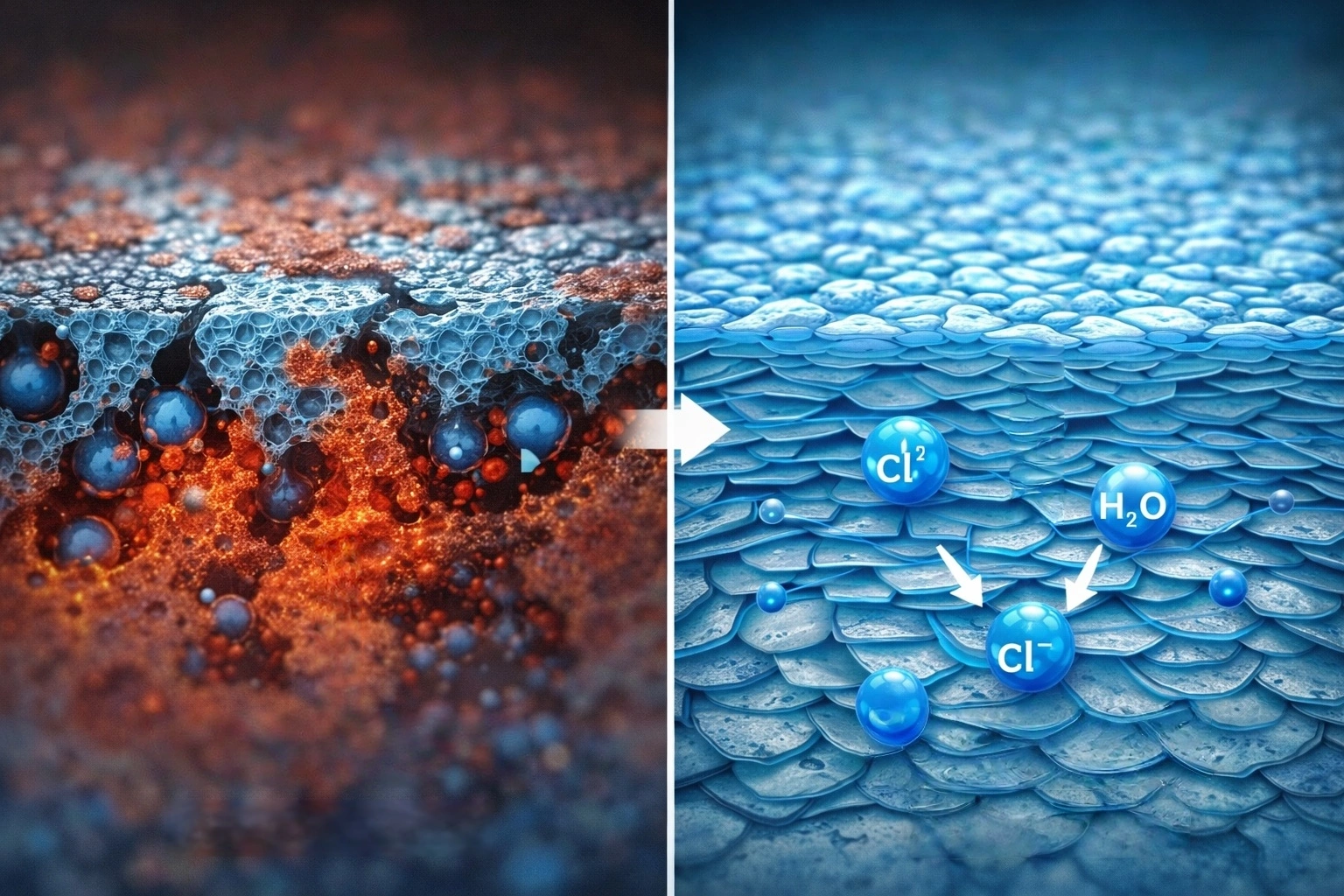
Organically Modified Montmorillonite (OMMT) is a layered-silicate nanofiller obtained by cation-exchanging natural sodium montmorillonite (Na⁺-MMT) with quaternary ammonium salts: single-platelet thickness ≈ 1 nm, lateral size 100 nm–1 500 nm, aspect ratio α=2L/t commonly 30–150; at a loading of 1 wt%–8 wt% in a polymer coating, the Nielsen tortuous-path mechanism extends the diffusion distance of water, dissolved oxygen and chloride ions by an order of magnitude, making it one of the well-established two-dimensional nanofiller routes for heavy-duty anticorrosion, barrier packaging, automotive OEM coatings and marine engineering coatings.
The three most common field failure scenarios all hinge on the transport rate of water, oxygen and Cl⁻: first, on coastal steelwork and bridges the mid-coat develops localized blistering and filamentous corrosion within 5–8 years; second, on automotive chassis parts and commercial vehicle bodies under de-icing salt conditions the cathodic disbondment front creeps outward from the scratch on both sides; third, the interior topcoat of chemical storage tanks loses gloss early and softens under solvent immersion. The traditional answer is a thicker film or more glass flake, but added thickness brings cost, drying and internal-stress penalties; the appeal of OMMT lies precisely in that — at under 5 wt% loading, barely changing the application viscosity ceiling — it turns a dense coating into "a labyrinth of stacked layers".
TL;DR: six criteria at a glance
- Interlayer spacing d₀₀₁ is the most direct evidence of intercalation: raw sodium montmorillonite sits at ≈ 1.2 nm (humidity dependent), Cloisite 15A commonly at 3.1–3.2 nm, Cloisite 30B at ≈ 1.8–1.9 nm, and after exfoliation the low-angle XRD peak (2θ<5°) weakens or even disappears; grade-specific data should follow the supplier TDS and measured XRD.
- Cation exchange capacity CEC sets the ceiling for quaternary ammonium grafting: the theoretical CEC of montmorillonite is ≈ 80–120 meq/100 g, and the organophilic substitution degree is usually designed at 90%–110% of CEC; beyond this range free quaternary ammonium is introduced instead and the coating's early water resistance suffers.
- Typical loading window 1 wt%–8 wt%: transmittance and mechanical gains usually show a turning point near 3 wt%–5 wt%; further addition pushes viscosity up and worsens dispersion; in PPO/PS blend systems the literature reports a percolation threshold of ≈ 4 wt% (open-literature figures, see References).
- Aspect ratio α in the Nielsen–Bharadwaj model is the core variable: Dc/D₀=(1−φ)/(1+αφ/2) assumes parallel, infinitely extended platelets, and the Bharadwaj correction adds finite length and orientation angle; at α=100 and φ=3 vol% the theoretical barrier factor falls in the 3–5× range.
- Open-literature case with epoxy + 2 wt%–5 wt% Cloisite 30B: neutral salt spray GB/T 1771-2007 / ISO 9227 improves from 500 h to 800 h–1 000 h, and low-frequency impedance |Z|0.01 Hz rises by 1–2 orders of magnitude; actual figures vary widely with formulation, film thickness and cure, and are listed here only as open-literature values.
- Judge exfoliation with "three legs together": low-angle XRD peak + TEM single-platelet distribution + the rise of the low-frequency storage modulus G′; relying on only one of them easily mistakes "intercalated but not exfoliated" for "fully exfoliated", and the barrier then falls clearly below theoretical expectation.
I. Crystal structure of montmorillonite and CEC
Montmorillonite is a 2:1 layered silicate: two silica tetrahedral sheets sandwich one alumina octahedral sheet, and the interlayer charge is compensated by exchangeable cations such as Na⁺, Ca²⁺ and K⁺, which also hold one or more layers of adsorbed water. It is exactly this "exchangeable cations + weak van der Waals bonding" structure that makes OMMT a nanofiller combining the following three features at once: its interlayer spacing can be chemically designed, its platelets can be mechanically exfoliated, and it can work at loadings below 1 wt%.
CEC (Cation Exchange Capacity) is the anchor for choosing the quaternary ammonium dosage and judging the substitution degree. Natural montmorillonite typically has a CEC between 80–120 meq/100 g; the higher it is, the more exchangeable interlayer cations and the larger the organophilization headroom. Engineering practice designs the substitution degree at "90%–110% of theoretical CEC": too low leaves bare Na⁺ between the layers and the hydrophobic conversion stays incomplete; too high leaves surplus quaternary ammonium free outside the platelets, creating an early water-uptake channel in the coating.
1.1 Division of labor between montmorillonite and other layered silicates
Industrially common layered silicates go well beyond montmorillonite. When choosing a filler, looking only at "whether it is a nanosheet" is not enough — aspect ratio, interlayer chemistry, temperature resistance and acid/alkali resistance also matter.
| Filler | Crystal type | Typical single-platelet size | Aspect ratio α | CEC / meq·100 g⁻¹ | Main coating use |
|---|---|---|---|---|---|
| Montmorillonite MMT / OMMT | 2:1 octahedral aluminosilicate, expandable | Thickness ≈1 nm, lateral 100–1 500 nm | 30–150 | 80–120 | Heavy-duty anticorrosion, barrier topcoat, waterborne primer, automotive OEM clearcoat |
| Sepiolite | 2:1 chain-layered silicate, one-dimensional rod | Width 20–40 nm, length 0.5–5 μm | 20–100 | 20–40 | Thixotropic anti-settling, high-temperature coatings; barrier contribution weaker than MMT |
| Kaolin (exfoliated) | 1:1 layered aluminosilicate | Thickness 0.1–1 μm, platelet diameter 1–10 μm | 5–20 | <15 | Extender pigment, barrier filler (micron scale), fire-resistant coatings |
| Laponite synthetic lithium silicate | 2:1 disc shape, disc diameter 25 nm | Thickness ≈1 nm, diameter ≈25 nm | ≈5 | ≈80 | Thixotropy in waterborne paints, emulsion-polymerization stabilizer; weak barrier |
| Mica / titanium dioxide-coated mica | 2:1 layered, natural cleavage | Thickness 10–200 nm, platelet diameter 5–100 μm | 50–200 | 5–20 | Physical shielding, anti-permeation topcoat; low exfoliation degree |
Three conclusions can be read from this table: only montmorillonite and Laponite have an exchangeable interlayer with CEC≥80 — so only they allow true "chemical intercalation"; sepiolite is a one-dimensional rod — strong thickening but weak barrier; exfoliated kaolin and mica are micron-scale — they work through packing density rather than a nano effect, and loadings often need 5 wt%–15 wt% before a clear drop in transmittance appears. This is also why this article treats OMMT as a subject of its own.
II. Three routes of quaternary-ammonium organic modification
Converting Na⁺-MMT into OMMT runs industrially through quaternary-ammonium cation exchange; laboratories have also used pyridinium, imidazolium and amino silanes. The choice of quaternary ammonium salt directly sets interlayer spacing d₀₀₁, thermal stability, polarity and resin compatibility. In engineering practice they fall into three families by alkyl-chain arrangement.
2.1 Single-chain / double-chain / hydroxyalkyl: the three siblings
Single-alkyl quaternary ammonium (e.g. octadecyltrimethylammonium, code 9AT) tends to lie tilted between the layers, lifting d₀₀₁ from 1.2 nm to ≈ 2.4 nm; its polarity is weak, suited to non-polar matrices such as polyamide and polyolefin. Dialkyl dimethyl quaternary ammonium (industrial grades often called 2M2HT / 2HT2M) forms a "parallel bilayer" arrangement with d₀₀₁ typically 3.1–3.6 nm and relatively easy exfoliation. Hydroxyalkyl quaternary ammonium (methyl·bis(hydroxyethyl), code MT2EtOH) introduces two –OH groups, so d₀₀₁ actually dips back to 1.8–1.9 nm, but its hydrogen bonding with polar resins such as epoxy and waterborne polyurethane is stronger, making it a common grade in epoxy systems.
Taking common market grades as examples (data from suppliers' open TDS and literature compilations; each batch to be confirmed by measurement): Cloisite Na⁺ interlayer spacing ≈1.2 nm, Cloisite 15A ≈3.1 nm, Cloisite 20A ≈2.8 nm, Cloisite 30A ≈2.5 nm, Cloisite 93A ≈2.2 nm, Cloisite 25A ≈3.6 nm, Cloisite 30B ≈1.8 nm. The core of grade selection is not "the larger the spacing the better" but matching matrix polarity and the target curing temperature: when epoxy cures at 180 ℃, hydroxyalkyl quaternary ammonium easily fails through Hofmann elimination and must be replaced by thermally more stable imidazolium or phosphonium; for a waterborne acrylic baked at 80 ℃ the reverse holds, and the polarity-matched 30B can be used.
Beyond quaternary ammonium salts there are two niche routes worth recording: one uses amino silane coupling agents (e.g. γ-aminopropyltriethoxysilane KH-550), which condense with the montmorillonite interlayer silanols while also bonding onto the resin end; the other is reactive intercalation monomers — hydroxyethyl methacrylate (HEMA) is intercalated first and then polymerized in situ, so the platelets are covalently "stapled" into the resin network and long-term barrier decay is smaller. In open literature both routes still trail quaternary-ammonium exchange in cost and industrialization, so they are not developed here.
III. Solution intercalation, melt intercalation and in-situ polymerization intercalation
Moving OMMT from the "filler bag" into the "coating system" follows three mainstream process routes, chosen by resin form, VOC ceiling, production capacity and available equipment.
Solution intercalation: the resin is dissolved in a polar solvent (cyclohexanone, xylene, DMF, NMP or ethanol/water), shear-mixed with OMMT at high speed and then dried into a film. This is the earliest laboratory route and still the mainstream industrial method for waterborne paints and low-solids automotive OEM clearcoats — the polar solvent enters the interlayer and, together with the stirring energy, opens d₀₀₁ up; the downside is solvent recovery and VOC compliance cost. Melt intercalation: solvent-free, a twin-screw extruder melt-blends resin and OMMT directly at 180 ℃–260 ℃; widely used for powder coatings, polyester/PA hot-melt adhesives and pellet masterbatch, with higher energy consumption and equipment thresholds. In-situ polymerization intercalation: the monomer (ε-caprolactam, acrylate or epoxy prepolymer) is pushed into the interlayer first, then polymerization is initiated so the growing chains "lever" the platelets apart, giving a favorable exfoliation degree; typical uses are nylon 6/clay masterbatch and UV-curable adhesives. To weigh the three in engineering, start with one question: how many grams per liter of VOC does the system allow? The answer eliminates at least one route at once.
On the dispersion-equipment side, the widely held industrial rule of thumb is high-speed dispersion (1 000–1 500 r/min, 15–30 min) + bead mill or three-roll mill (fineness ≤15 μm). Below this threshold OMMT stays in the coating as intercalated stacks of 10–30 layers: the low-angle XRD peak is still there, but the barrier reaches only three to five tenths of the theoretical value.
IV. Exfoliation criteria: XRD d₀₀₁ + TEM + low-frequency rheology
The morphology of OMMT in a coating is graded by "how far the interlayer has expanded": phase separation (tactoid) — the platelets remain stacked as in the raw mineral, with no clear change in d₀₀₁; intercalated — resin molecules enter the interlayer, d₀₀₁ rises by 0.5–2 nm and the low-angle XRD peak shifts toward smaller angles; exfoliated — the platelets are dispersed as single layers in the resin and the low-angle XRD peak (2θ<5°) weakens markedly or disappears. Judging exfoliation cannot rely on XRD alone:
- XRD: Cu Kα radiation λ=0.154 06 nm, scan 2θ=1°–10°, back-calculating d₀₀₁ from Bragg's law nλ=2d·sinθ. The larger d₀₀₁ is, the more complete the intercalation; a vanishing <5° peak means most platelets have been exfoliated. But the apparent gap between d₀₀₁=3.5 nm and d₀₀₁=4.0 nm says nothing about barrier quality — platelet orientation must also be checked.
- TEM: directly shows whether 1 nm-class single platelets are uniformly distributed; it is the "gold standard" but demands careful preparation (ultramicrotomy of 60–80 nm, RuO₄ or osmium tetroxide staining); count at least 5 fields of view per batch.
- Low-frequency rheology: a rise of 1–2 orders of magnitude in storage modulus G′ near 0.01 rad/s, together with a "low-frequency plateau", is the physical fingerprint of platelet-network percolation; it is faster than XRD and suits in-line spot checks.
| Morphology | d₀₀₁ / nm | Low-angle XRD peak | TEM appearance | G′ low-frequency rise | Typical barrier factor |
|---|---|---|---|---|---|
| Phase separation (tactoid) | ≈ raw ore 1.2 | 2θ ≈ 7°, sharp peak | Agglomerates stacked 15–30 layers | Not noticeable | 1–1.5× |
| Intercalated | 2.5–3.5 | 2θ ≈ 2.5°–3.5°, still strong | Regular fringes, expanded interlayer | 0.5–1 order of magnitude | 2–4× |
| Exfoliated | >5 or no peak | 2θ<2° markedly weakened | Single platelets randomly dispersed | 1–2 orders of magnitude | 4–10× (bounded by φ and α) |
V. Nielsen–Bharadwaj tortuous path and aspect ratio
The classic model of the barrier mechanism is the "tortuous path" proposed by Nielsen in 1967: impermeable platelets force diffusing molecules to go around them, lengthening the effective diffusion path. Assuming platelets parallel and far larger than the coating thickness, the relative diffusion coefficient is Dc/D₀=(1−φ)/(1+αφ/2), where φ is the platelet volume fraction and α=2L/t the aspect ratio. Bharadwaj corrected two premises in 2001 — finite platelet length and an orientation angle θ relative to the coating plane — and obtained the corrected form: Dc/D₀=(1−φ)/(1+(α·S/4)φ·tan⁻¹(…)) (full derivation in Bharadwaj 2001); the engineering meaning is "the more parallel the platelets lie to the coating surface and the narrower the orientation spread, the better the barrier".
| φ / vol% | α = 30 | α = 50 | α = 100 | α = 150 | α = 300 |
|---|---|---|---|---|---|
| 1 | 1.7× | 2.6× | 5.0× | 7.5× | 15.0× |
| 2 | 2.4× | 4.0× | 8.0× | 11.5× | 22.5× |
| 3 | 3.0× | 5.2× | 10.5× | 15.0× | 30.0× |
| 5 | 4.0× | 7.0× | 14.0× | 20.0× | 40.0× |
| 8 | 5.4× | 9.4× | 18.7× | 26.7× | 53.3× |
This table shows two things: first, exfoliating matters more than "adding more" — moving α from 30 to 100 buys far more barrier than raising φ from 1% to 3%; second, at 8 vol% the theoretical barrier factor still climbs, yet engineering practice usually tops out already between 3% and 5% — because high-α platelets re-stack into the intercalated state in the shear field and the "apparent α" falls back. This is also the physical reason 3 wt%–5 wt% is the sweet spot across OMMT cases.
VI. The loading–viscosity–mechanics trade-off triangle
The gains from raising OMMT loading are not monotonic; three curves pull against each other: transmittance falls, viscosity rises, and toughness goes up first and then down. Formulation work means finding a feasible window between three thresholds:
- Viscosity ceiling: airless spraying requires a 60 s Ford cup #4 viscosity ≤60 s; a waterborne alkyd topcoat at 25 ℃ should stay ≤3 000 mPa·s on a Brookfield viscometer; above this line, either cut the loading or move to high shear or bead milling.
- Toughness floor: the GB/T 6739 / ISO 1522 pendulum damping hardness must not worsen by more than 1 grade; the GB/T 6742 or ASTM D522 cylindrical mandrel bend ≤3 mm must not crack; impact strength GB/T 1732 ≥40 cm is the usual engineering bottom line.
- Adhesion floor: GB/T 9286-2021 cross-cut ≤ grade 1 and GB/T 5210-2006 pull-off ≥3 MPa; a loading that is too high drags adhesion down through internal stress and hardener-ratio drift.
Empirical window: solventborne epoxy 2 wt%–4 wt%, waterborne acrylic dispersion 3 wt%–5 wt%, automotive OEM clearcoat 1 wt%–2 wt% (to avoid haze pickup), UV-cure systems 0.5 wt%–2 wt% (limited by light transmittance). These figures summarize common ranges from open literature and supplier TDS, not recommended values from our plant; every real project must redo design validation for its actual resin, hardener and application method.
VII. Key data (eight items, each with units)
- Sodium-montmorillonite interlayer spacing d₀₀₁ ≈ 1.2 nm (humidity dependent; expandable 2:1 silicate).
- Theoretical montmorillonite CEC 80–120 meq/100 g; industrial organophilic substitution is usually designed at 90%–110% of CEC.
- OMMT single-platelet thickness ≈ 1 nm, lateral size 100 nm–1 500 nm, aspect ratio α 30–150.
- Cloisite-series grades show d₀₀₁ commonly at 1.8 nm (30B)–3.6 nm (25A); confirm by per-batch measured XRD.
- Theoretical transmission factor: at φ=3 vol% and α=100, Dc/D₀ ≈ 1/10.5 (Nielsen simplified model).
- In epoxy/hardener systems 3 wt%–5 wt% OMMT is the common barrier–viscosity balance window; above 6 wt% viscosity usually spikes.
- Open-literature case: epoxy + 2 wt% Cloisite 30B, neutral salt spray GB/T 1771-2007 / ISO 9227 from 500 h → 800 h–1 000 h, with low-frequency impedance |Z|0.01 Hz rising 1–2 orders of magnitude.
- The Hofmann-elimination critical temperature of quaternary ammonium salts is ≈ 180 ℃–200 ℃; beyond it olefins and tertiary amines are released, yellowing the coating and collapsing the interlayer; high-temperature cure systems must switch to imidazolium or phosphonium organoclays.
VIII. Route comparison with other two-dimensional nanofillers
OMMT is not the only two-dimensional filler. Graphene, MXene, hexagonal boron nitride and lamellar mica all contribute tortuous paths, but each is constrained on cost, density, color depth, weatherability and conductivity. Before choosing a route, ask: does the project need a barrier, thermal conductivity, electrical conductivity, or merely decorative shielding?
| Dimension | OMMT | Modified graphene | MXene (Ti₃C₂Tₓ) | Hexagonal boron nitride h-BN |
|---|---|---|---|---|
| Typical loading | 1 wt%–8 wt% | 0.05 wt%–1 wt% | 0.5 wt%–5 wt% | 2 wt%–10 wt% |
| Price level (open market) | Low (tens of yuan/kg) | Mid-high (hundreds–thousands of yuan/kg) | High (mostly at the lab stage) | Mid-high |
| Effect on coating color depth | Light yellow; usable in white/light topcoats | Dark grey–black | Dark gold–grey | White; compatible with light shades |
| Conductivity | Insulating | Percolating to conductive | Percolating to conductive | Insulating |
| Barrier mechanism | Tortuous path + interlayer chemical anchoring | Tortuous path + high density | Tortuous path + Ti-OH inhibitor synergy | Tortuous path + high thermal conductivity |
| Common failure | Quaternary ammonium thermal decomposition, moisture re-uptake | Dispersion agglomeration, transmittance loss | Hydrolytic oxidation, galvanic corrosion risk | In-plane slip reducing adhesion |
Three practical rules: for cost-sensitive heavy-duty anticorrosion, choose OMMT; for antistatic or conductive coatings, choose graphene / MXene rather than OMMT; where thermal conductivity plus electrical insulation is required (LED substrates, e-drive housings), choose h-BN or an h-BN/OMMT blend. For the mechanism and engineering-boundary analysis, see the on-site articles MXene (Ti₃C₂Tₓ) anticorrosion coatings and dispersion and engineering boundaries of graphene-modified barrier coatings.
IX. Engineering implementation notes
9.1 Dispersion energy, color-paste compatibility and batch variability
OMMT is a "low addition, high sensitivity" filler: batch-to-batch swings in d₀₀₁ and free-water content within the same grade cause visible formulation drift. Three routine controls in engineering: incoming XRD spot check of d₀₀₁ (once per batch, a deviation within ±0.2 nm is acceptable); grinding fineness ≤15 μm (scratch fineness gauge); and a compatibility trial before pre-mixing with color pastes or anticorrosive pigments such as carbon black, TiO₂ and zinc phosphate — highly polar inorganic pigments grab the interlayer sites and displace the quaternary ammonium, causing localized yellowing of the coating. See the dispersion-equipment section of the on-site article nano-SiO₂ dispersion and anti-settling: OMMT needs longer dispersion time, not larger dispersion energy.
9.2 Thermal stability, UV and moisture re-uptake
The Hofmann elimination of quaternary-ammonium organofunctional agents is the most easily overlooked failure: when curing, baking or laser marking approaches 180 ℃, dialkyl quaternary ammonium releases olefins and tertiary amines, so d₀₀₁ collapses back, the color yellows and the barrier decays; the fix is imidazolium- or phosphonium-modified clays rated to higher temperatures, or a lower process peak temperature. Under UV aging the OMMT platelets themselves are stable, but matrix degradation leaves them exposed, raises surface roughness and lowers reflectivity — the same physical mechanism as SRI decay in radiative-cooling coatings, see radiative-cooling nanocoatings: spectral selection, atmospheric window and weatherability boundaries. Moisture re-uptake is common in hydroxyalkyl quaternary ammonium systems: the –OH groups and residual Na⁺ jointly attract water vapor, and after prolonged water immersion (GB/T 1733 / ISO 2812) the coating's water absorption runs high; the countermeasure is to cut the loading below 3 wt% and seal with an epoxy or polysiloxane topcoat.

X. Frequently asked questions (FAQ)
- Q1: How much OMMT should be added to pay off, and why is more not better?
A: in most resin systems the sweet spot sits at 2 wt%–5 wt%. The Nielsen model shows the barrier factor rising monotonically with φ, but α is knocked back to its starting point by "re-stacking" as loading increases; meanwhile viscosity climbs with a power of 2 or higher and the application window narrows. Below 3 wt% it is usually "more loading, more barrier", and above 5 wt% often "more brittle and harder to spray". - Q2: Does OMMT affect coating transparency or color?
A: yes. Single 1 nm-class platelets scatter visible light very weakly, so below 2 wt% the haze impact on a clearcoat is negligible; but organoclay residue or poor dispersion forming 10–30-layer tactoids visibly clouds the film. Dark systems are barely affected; for light or transparent systems keep the loading ≤2 wt% and use bead milling. - Q3: Can OMMT be blended with graphene/MXene?
A: yes, and it is a hot direction in recent years. OMMT supplies large-area platelets and chemical anchoring, while graphene/MXene supply high electrical or thermal conductivity or inhibitor synergy; the literature shows 1 wt%–3 wt% OMMT + 0.1 wt%–0.5 wt% graphene/epoxy can deliver 1 000 h salt spray together with a 10⁻³–10⁻² S/cm surface conductivity. In engineering, make sure the dispersion processes and shear directions of the two fillers do not cancel each other out. - Q4: How do I know my OMMT is truly exfoliated rather than merely intercalated?
A: look at all three legs together: the low-angle XRD peak (2θ<5°) should weaken markedly or vanish; TEM should show randomly dispersed single platelets across at least 5 fields of view; and low-frequency rheology should show a G′ rise of ≥1 order of magnitude. Relying on XRD alone easily mistakes "intercalated with poor ordering" for "fully exfoliated". For in-line spot checks, low-frequency rheology suffices; add XRD and TEM when something looks off. - Q5: Which weatherability / anticorrosion standards can an OMMT coating pass?
A: OMMT is a filler, not a system, so the final performance still depends on the resin. Common acceptance combinations: neutral salt spray GB/T 1771-2007 / ISO 9227, xenon-arc accelerated weathering GB/T 1865-2009 / ISO 11509, damp heat resistance GB/T 1740-2007, liquid resistance GB/T 9274-1988 and pull-off adhesion GB/T 5210-2006. For marine C5-M systems, refer to the laboratory performance test methods in GB/T 30790.5-2014 and ISO 12944-9:2018. - Q6: Why does OMMT dispersion often fail in waterborne systems?
A: water molecules compete for intercalation and displace the quaternary ammonium; in addition, waterborne resin latex particles of 100–300 nm are close to the OMMT single-platelet size, so co-agglomeration is easy. The engineering practice: pre-wet the OMMT with a little ethanol/propylene glycol into a paste, then add it to the emulsion under high shear (800–1 200 r/min, 15–30 min); stabilize the pH at 8–9; and avoid adding an anionic dispersant at the same time, which triggers flocculation. - Q7: Can OMMT work together with silane impregnation and anti-graffiti coatings?
A: yes. Silane impregnation follows the "hydrophobic pore wall" route in concrete or mineral substrates, while OMMT follows the "diffusion barrier" route inside the coating body, so the two are complementary; see the on-site silane-impregnation water-repellent coating. Anti-graffiti coatings rely on low surface energy (see the fluorine-free water-repellent route); OMMT goes into the mid-coat rather than the topcoat, so stacking them does not hurt anti-graffiti performance.
References and notes on the figures
- Nielsen, L. E. Diffusion in Heterogeneous Media I. Barrier Diffusion in a Oriented-Continuous Filler System. J. Macromol. Sci. 1967, C1(1): 929–942 — the original tortuous-path model.
- Bharadwaj, R. K. Modeling the Barrier Properties of Polymer Layered Silicate Nanocomposites. Macromolecules 2001, 34(26): 9189–9192. DOI: 10.1021/ma011090e — finite platelet length and orientation-angle correction.
- Alexandre, M.; Dubois, P. Polymer-Layered Silicate Nanocomposites: From Fabrication to Properties. Materials Science and Engineering R: Reports 2000, 28(1–2): 1–63. DOI: 10.1016/S0927-796X(00)00012-7 — OMMT review and intercalation-route classification.
- Giannelis, E. P. Polymer Layered Silicate Nanocomposites. Advanced Materials 1996, 8(1): 29–43. DOI: 10.1002/adma.19960080105 — the foundational review of polymer/clay nanocomposites.
- GB/T 10125-2021 "Corrosion tests in artificial atmospheres — Salt spray test" (identical adoption of ISO 9227:2017) and GB/T 1771-2007 "Paints and varnishes — Determination of resistance to neutral salt spray".
- GB/T 30790.5-2014 "Paints and varnishes — Corrosion protection of steel structures by protective paint systems — Part 5: Protective paint systems" and ISO 12944-9:2018 Part 9, laboratory performance test methods.
- GB/T 1766-2008 "Paints and varnishes — Methods for assessing the degree of alteration of a coating" and GB/T 1865-2009 "Paints and varnishes — Artificial weathering and exposure to full solar radiation — Maximum-energy exposure with filtered xenon-arc lamps".
- GB/T 9286-2021 "Paints and varnishes — Cross-cut test", GB/T 5210-2006 "Paints and varnishes — Determination of pull-off strength" and GB/T 6739-2022 "Paints and varnishes — Pendulum damping test".
- Zhu Xiaoqi et al.: "Study of PBAT composites modified with organic montmorillonite", Guangzhou Chemical Industry 2015, 43(9) — the d₀₀₁ of OMMT-DK2 expands from 1.923 nm to 3.2–3.6 nm; tensile strength 33.25 MPa at 3 wt% and elongation at break 860% at 5 wt% (cited explicitly as an open-literature case, not as a guaranteed measured value from our plant).
- Cloisite-series grade parameters are taken from the open TDS of Southern Clay Products (now part of BYK); per-batch data follow the factory inspection report issued for each batch.
- All specific loading levels, times, temperatures and gain factors for coating systems in this article are open-literature or supplier-TDS figures, not guaranteed values measured by our plant; every real project must be re-validated with the formulation and process of our plant.
Last updated: 2026-11-17 · Kexin New Materials (Guangdong) Co., Ltd. · B2B technical reference; supply under EXW / FOB terms.