Introduction: Robotic spraying — not "replacing human hands" but "surpassing human hands"
Automotive OEM painting line—outer surfaces (hood/doors/fenders/roof) are 100% automatically sprayed by robots. Painting robots are not just "fatigue-free painters"; their repeat positioning accuracy (±0.2mm), constant gun travel speed (±1mm/s), and precise control of atomization parameters far exceed even the most skilled manual spraying technicians. However, the film thickness uniformity of robot painting (target ±5μm) cannot be automatically achieved merely by the robot's "automation"; it requires (1) mathematical planning of spraying trajectories for complex surfaces (CAD models) (optimization of gun distance/speed/overlap rate); (2) collaborative optimization of the three major parameters of the electrostatic rotary bell (bell speed/shape air/high voltage)—any parameter deviating from the optimum will degrade the film thickness distribution; (3) virtual verification via CFD (Computational Fluid Dynamics) simulation to predict film thickness distribution before physical spraying—reducing paint and time waste in physical trials.
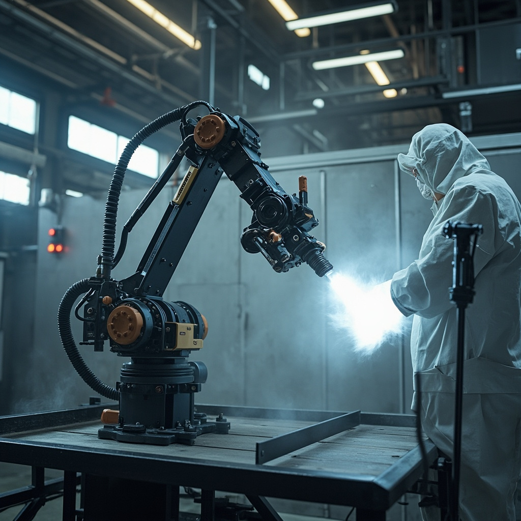
I. Synergistic Optimization of the Three Key Parameters of Electrostatic Rotary Bell
| Parameter | Range | Mechanism | Consequences of Too High | Consequences of Too Low |
|---|---|---|---|---|
| Bell speed (krpm) | 30-60 | Centrifugal atomization / speed ↑ → droplet ↓ → paint mist fineness ↑ | Paint mist particles too fine → dispersion ↑ / transfer efficiency ↓ | Coarse atomization → orange peel / particles on coating |
| Shaping air (MPa) | 0.1-0.4 | Constrain paint mist fan / control spray width | Spray width too narrow → insufficient overlap rate → uneven film thickness | Spray width too wide → paint mist dispersion ↑ / transfer efficiency ↓ |
| High voltage (kV) | 60-90 | Paint mist electrification / electrostatic adsorption / wrapping effect | >90 — air breakdown → spark → fire risk | <50 — weak electrostatic effect → transfer efficiency ↓ |
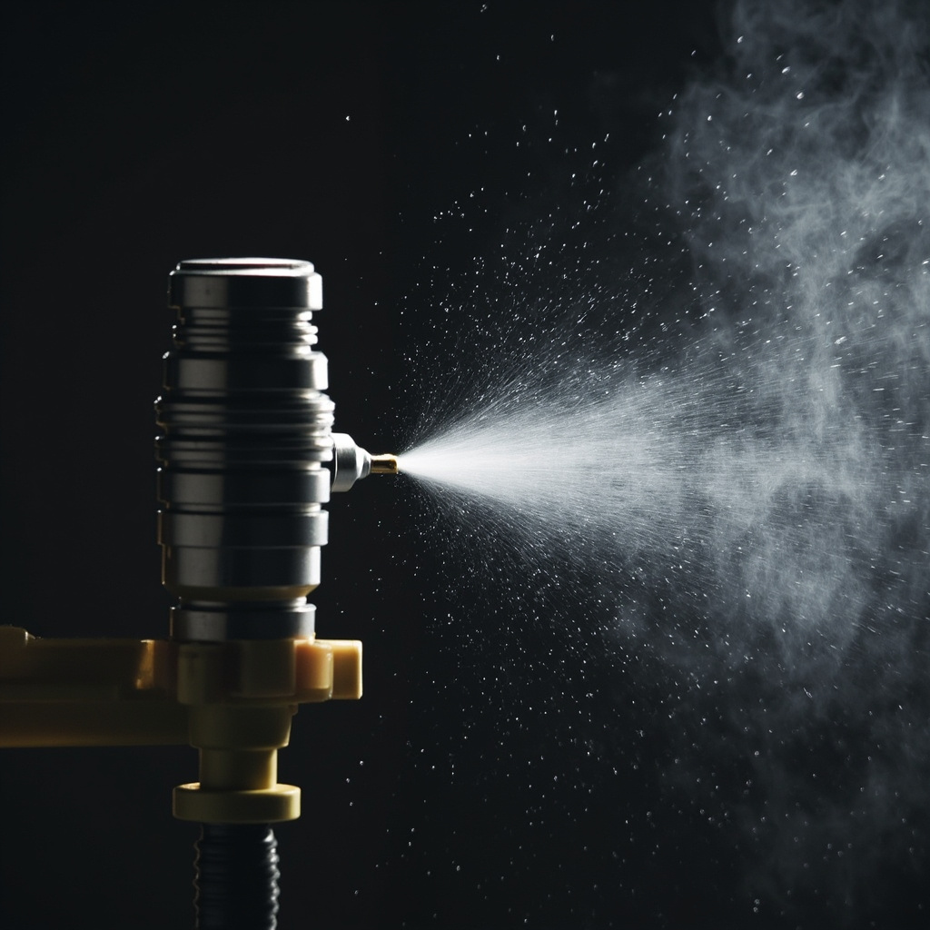
II. Effect of Spray Trajectory Overlap Rate on Film Thickness Distribution
| Overlap Rate (%) | Film Thickness Uniformity | Paint Utilization Rate | Applicable Scenarios |
|---|---|---|---|
| 50 (just touching) | Poor (±15μm / large peak-valley film thickness difference) | High | Not recommended |
| 60-65 | Good (±8μm) | Medium | Mid-coat / primer (lower appearance requirements) |
| 70-75 | Excellent (±5μm / recommended) | Medium (standard) | Topcoat / clearcoat (highest appearance requirements) |
| >80 | Excellent (±3μm / but severe waste) | Low (>50% overspray) | Only for extremely high requirements (show cars / prototype cars) |
Technical deepening: systematic optimization methods for process parameters (DOE experimental design)
The optimization of coating production processes should not rely on the "trial-and-error method" but should adopt the scientific method of DOE (Design of Experiments). Taking the dispersion process as an example—factors affecting quality (linear velocity/time/filling rate/temperature), 4 factors each at 3 levels—a full factorial requires 81 experiments—DOE uses orthogonal experiments L9 (9 times) or response surface methodology (27 times) to greatly reduce the number of experiments—while simultaneously obtaining the main effects and interactions of each factor. For example, it is found that "the interaction of linear velocity × time is significant": high linear velocity + short time and low linear velocity + long time can achieve the same dispersion effect—but the former saves over 20% energy.
In DOE analysis, interpretation of the P-value — P95% confidence). The final output of DOE is a set of prediction models (polynomial regression equations) — input line speed/time/temperature → predict fineness/viscosity/gloss — providing formulation engineers with a "digital formulation optimization" tool.
Industry practice: from "master craftsman's feel" to "parameter standardization"
The common challenge in the coatings industry — when experienced veteran workers retire, their "feel" (mixing resistance / fineness gauge scraping / visual inspection of wet-film gloss) is taken away — new employees cannot replicate it. Transform the "feel" into quantifiable standard parameters (1) mixing resistance → viscometer reading; (2) fineness gauge scraping → fineness gauge reading (μm); (3) wet-film gloss → gloss meter (GU value). The "standard parameter card" for each process is posted next to the equipment — new employees operate according to the "card" rather than "by feel". "Parameter standardization" is a key step for coating factories to move from "workshop" to "factory".
FAQ
Q1: How do the "range of motion" and "speed limits" of each of the robot's six axes constrain spray trajectory planning?Axis 1 (base rotation / ±180° / fastest) — large-range rotation. Axes 4/5/6 (wrist) — high-speed precise posture adjustment — the spray gun's angle and distance control mainly relies on the three wrist axes. When the robot approaches a "singularity" (the boundary of each axis's range of motion), its motion becomes non-smooth (sudden acceleration changes) — spray trajectories should be avoided in these regions — otherwise the spray gun shakes → uneven film thickness.
Q2: Application of the three motion modes PTP (Point-to-Point) / CP (Continuous Path) / LIN (Linear) in spraying? Spraying must use CP or LIN mode (continuous path / constant speed along the entire trajectory) — spray gun speed is constant — ensuring uniform film thickness. PTP mode (fastest path / no trajectory constraint / each axis moves independently to arrive fastest) — only used for non-spraying movement (from standby position to spray start position) — cannot be used during spraying — spray gun motion speed and direction under PTP mode are both not constant.
Q3: What problems do the VOF (Volume of Fluid) and DPM (Discrete Phase Model) in CFD simulation solve respectively?VOF——simulates the continuous phase of paint mist (air flow field + macroscopic shape of the paint mist "cloud"). DPM——simulates discrete paint mist particles (independent trajectory/electrostatic force and gravity of each particle). The standard method for spray simulation——first use CFD to calculate the air flow field → then use DPM to calculate the movement of paint mist particles in the flow field + electrostatic field → finally integrate the particle deposition amount → obtain the film thickness distribution. The coupled calculation of VOF + DPM is extremely computationally intensive (a car body model takes days to weeks to compute)——usually used in R&D centers——real-time optimization on the production line is impractical.
Q4: Why is the robot's "TCP" (Tool Center Point) calibration the foundation of spraying quality?TCP is the spatial position of the spray gun tip that the robot "believes" — deviation between TCP and the actual spray gun tip >2mm — spraying distance deviation >2mm → film thickness change >10μm. TCP calibration — using a laser tracker / calibrated every 3-6 months — is the basic system of robot spraying maintenance. Common causes of TCP offset — mechanical collision (spray gun hits the car body or hanger) / thermal expansion / slight creep during long-term operation.
Q5: How does the "collision detection" of painting robots prevent million-level equipment losses?The spray gun of the painting robot (mounted on the wrist) — worth >100,000 RMB — a collision with the car body may cause the spray gun to shatter + robot joint damage + car body scrapping. The robot's built-in torque sensor detects abnormal torque (>2-3 times the normal painting torque) and brakes and stops within 10ms to reduce collision damage.
Q6: How does "Electrostatic Wrap-around" help with coating complex shapes?Static electricity charges the paint mist particles → particles move along the electric field lines → some particles bypass the front of the workpiece and reach the backAt complex shapes (stiffeners/grooves) — the electrostatic wrap-around effect enables the "shadow areas" unreachable by manual spraying to receive a thin coatingThis is one of the core advantages of electrostatic spraying over non-electrostatic spraying.
Q7: What is the "cleaning cycle" and color change efficiency of the rotary bell?The rotary bell requires thorough cleaning of the cup wall and shaping air ring for each color change, with a cleaning time of 15-30s per color—for one line (>10 colors/day), the cleaning and color change time accounts for >5% of production time. The Quick Color Change (QCC) system—completes color change and cleaning within 30-60s—compresses color change time by >50%.
Q8: What is the difference between "Offline Programming" and "Teach Pendant" for spray trajectories?Teach Pendant——The operator holds the teach pendant and manually guides the robot through the spray trajectory once——The robot records the trajectory——Time-consuming (>2h/vehicle model) and relies on operator experience——Currently only used for small batch/prototype vehicles. Offline Programming——Virtually plan the spray trajectory on the CAD model——Generate the robot program → download directly to the robot——Fast (<30min/vehicle model) + no need to occupy the production line——Is the standard method for mass-production OEM lines.
Q9: The robot's new "Hand Guiding" technology?The operator directly drags the spray gun by hand along the painting path once—the robot records force/torque sensor data—and automatically generates a smooth trajectory. Hand guiding is more intuitive and faster (>50% time saving) than teach pendant programming, but less precise than offline programming—suitable for small and medium batches / complex workpieces / rapid production changeover.
Q10: What are the most cutting-edge applications of AI in the field of painting robots?(1) Reinforcement Learning — AI autonomously explores the optimal painting trajectory in a virtual environment — after thousands of virtual painting sessions — outputs trajectories superior to manually programmed ones (film thickness uniformity improved by >10%); (2) Visual feedback — the robot's built-in online film thickness sensor (laser/infrared) — detects film thickness in real time after painting — feeds back to adjust the speed/gun distance of subsequent trajectories — forming a closed-loop control. AI + sensor closed-loop painting is the most cutting-edge R&D direction for painting robots.
FAQ: In-Depth Technical Q&A Supplement
Q11: How do the differences in domestic and international standards for this technology affect product exports?Domestic standards (GB) differ from ISO/ASTM standards in test methods and acceptance criteria. For example, salt spray testing—GB/T 1771 (equivalent to ISO 7253) has test conditions basically consistent with ASTM B117—but the rating systems (ISO 4628 vs ASTM D610/D714) differ—when providing test reports for exported products, you must simultaneously indicate the corresponding international standards, otherwise overseas customers cannot make a comparative assessment. It is recommended to list both GB and ISO/ASTM dual-standard indicators in the TDS (Technical Data Sheet) of exported products—to enhance the trust of international customers.
Q12: How to verify the long-term service performance of this technology in actual engineering?Laboratory accelerated testing (salt spray/QUV/cyclic corrosion) provides comparative data—but cannot fully replace actual outdoor exposure testing. Recommendations—(1) Set up outdoor exposure racks at both the factory location and typical customer locations (e.g., coastal C5-M/industrial C4)—conduct annual inspections of coating appearance/adhesion/film thickness changes—establish a company-owned outdoor service database; (2) Collaborate with universities/research institutes—combine enterprise data with academic research—enhance data credibility.
Q13: What should SMEs pay attention to when purchasing related raw materials/equipment?(1) The batch stability of suppliers is more important than unit price—it is recommended to require suppliers to provide COA data for >10 batches—and evaluate batch variation (CpK); (2) For equipment procurement, visit peers who have used the equipment for >2 years to understand the long-term reliability and after-sales service quality of the equipment—rather than relying only on the demonstration data from equipment suppliers; (3) For key raw materials (resin/curing agent)—maintain at least 2 qualified suppliers to guard against single-supply risk.
Q14: What is the current state and trend of digital transformation in this field?The digital transformation of the coatings industry is evolving from “point-based applications” (automation of individual equipment/processes) to ”system integration” (full-chain ERP+MES+PMS). Currently, the digitalization of small and medium-sized coatings factories has the ”highest ROI investment”: automatic batching systems + digitalization of quality control data—payback period of 1–3 years—which is the prioritized recommended direction. Future trend—AI + sensors enabling real-time optimization of process parameters—further reducing quality fluctuations between batches.
Q15: How can a newly entered coating engineer quickly master this technology?(1)Combine theory and practiceDo not only read literature without touching actual production—nor rely solely on experience without studying theory;(2)Build a “failure case archive”Every customer complaint/production anomaly/coating failure—record the root cause and resolution process—this is the most effective learning material;(3)Learn from suppliersTechnical personnel from resin/additive/pigment suppliers are carriers of "tacit knowledge" in this field—communicate more with them about solutions to specific problems.
Related Reading
Summary
Collaborative optimization of the six-axis trajectory planning for spraying robots (CP mode/70-75% overlap rate/200-300 mm gun distance) and the three parameters of electrostatic rotary bells (30-60 krpm rotation speed/0.1-0.4 MPa shaping air/60-90 kV high voltage) is the core to achieving ±5 μm uniform film thickness. CFD simulation (VOF+DPM) predicts film thickness distribution in a virtual environment—reducing physical trial-and-error costs. Kexin New Materials provides automotive painting customers with technical support for robot spraying parameter optimization and film thickness simulation.