Since graphene was isolated and confirmed to be stably existent in 2004, it has been hailed as the "King of New Materials" and has sparked a sustained boom in the field of anti-corrosion coating. Graphene Anti-corrosion Coating claims to leverage the extremely dense barrier capability of single-layer carbon atoms to significantly extend the service life of steel substrates, while also providing conductive, thermal conductive, and static-dissipative functions for equipment. However, market promotions are mixed: some so-called "graphene paint" actually contain negligible amounts of addition, serving merely as a marketing concept; some have inadequate dispersion processes, where graphene agglomeration instead becomes corrosion initiation points, producing the opposite of the intended effect. This article objectively and rigorously dissects the true engineering value of graphene coatings from mechanism, dispersion, performance to selection and standards, helping engineers and purchasers establish a verifiable and citable judgment framework, and avoiding being misled by conceptual packaging.
As a new material technology supplier focused on functional coatings, Kexin New Materials (kexinMaterials) has continuously invested in R&D and mass-production validation in the direction of functional filler-modified coatings. On the premise of not exaggerating or fabricating values, this article combines public standards and mechanism research to clearly explain graphene conductive anti-corrosion coatings, for reference in protection design for industries such as new energy, marine engineering, and petrochemical storage and transportation.
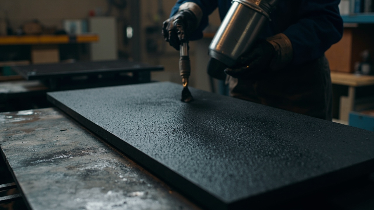
I. Why Graphene Can Prevent Corrosion: Lamellar Maze Effect
To understand graphene's anti-corrosion contribution, one must first understand its structural characteristics. Graphene is a two-dimensional sheet formed by single-layer sp² hybridized carbon atoms arranged tightly in a honeycomb pattern, with a theoretical thickness of only about 0.335 nanometers, an extremely high aspect ratio, and itself is almost impermeable to air and water. After uniformly dispersing graphene in an organic coating matrix, corrosive media—water, oxygen, chloride ions—if they are to penetrate the coating to reach the metal substrate, must detour around countless layers of graphene sheets, and the diffusion path is greatly extended, which is the "Tortuosity" repeatedly mentioned by academia and industry.
The essence of the maze effect is to increase the effective diffusion distance of corrosive media in the coating. According to classic diffusion theory, when flake fillers with high aspect ratio are introduced into the coating, the tortuous path required for media penetration is closely related to the filler volume fraction, aspect ratio, and orientation. The two-dimensional sheet aspect ratio of graphene is much higher than that of traditional micaceous iron oxide (MIO) and glass flakes, so at the same additive amount, it can theoretically more significantly reduce the permeability of water, oxygen, and ions.
More importantly, when graphene sheets form a certain mutual overlap in the coating, a continuous physical barrier network can be constructed within the shielding layer, further reducing coating porosity and improving overall density. This shares the same origin as the micaceous iron oxide sheet shielding mechanism, but graphene sheets are thinner and denser, with theoretically higher shielding efficiency. It must be emphasized that the word "theoretically" is extremely critical: whether graphene can truly exert the maze effect depends entirely on whether it achieves uniform, single-layer dispersion in the resin, rather than existing as graphite flake agglomerates.
II. Electrical and Thermal Conductivity: Additional Functions Beyond Anti-corrosion
Another most striking attribute of graphene is its excellent electrical and thermal conductivity. Single-layer graphene has an extremely high intrinsic carrier mobility, with conductivity reaching the order of 100,000 amperes per meter (theoretical value), and thermal conductivity is also among the highest tier of known materials. In the coating, as long as graphene forms a conductive network in an appropriate amount, it can endow the material with the following additional functions:
First, static dissipation. When the surface resistance of the coating drops to the order of 100,000 ohms to 100 million ohms (i.e., 10⁵–10⁸ Ω), it can be used for static dissipation in flammable and explosive environments, which is of great significance for explosion-proof scenarios such as petrochemical storage tanks, oil pipelines, and painting workshops. For more general conductive and electromagnetic shielding (EMI) coating systems, further refer to this batch of articles Conductive Coating EMI Shielding: Conductive Fillers and Shielding Effectiveness.
Second, cathodic protection synergy. Some studies attempt to compound graphene with zinc powder, expecting to use graphene's conductive network to more uniformly transmit the sacrificial protection of zinc powder, alleviating the local protection insufficiency caused by "islanding" of zinc powder in traditional epoxy zinc-rich primer. Such composite ideas are still in the engineering verification stage and must be supported by same-condition data.
Third, thermal conduction and dissipation. The graphene network can assist heat conduction, suitable for occasions such as power device housings and battery module structural parts that require both anti-corrosion and auxiliary heat dissipation.
It must be clearly recognized that conductivity and insulation are a pair of contradictory demands. If the goal is pure anti-corrosion with insulating protection (such as high-voltage battery housings, live control boxes), conductive graphene should not be introduced; graphene anti-corrosion coatings are more used in composite conditions of "requiring static dissipation or heat dissipation while also requiring high anti-corrosion." Misapplying conductive graphene to insulating occasions will directly destroy electrical isolation, which is one of the most easily overlooked and most dangerous errors in selection.
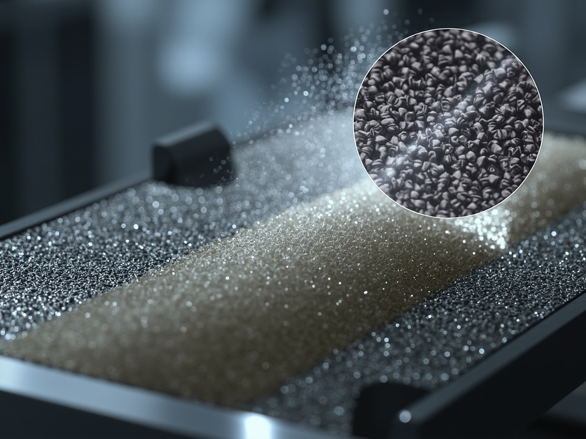
III. The Real Engineering Difficulty: Dispersion and Agglomeration
In graphene anti-corrosion applications, nine out of ten successes or failures depend on "dispersion." Single-layer graphene has a huge specific surface area and extremely strong interlayer van der Waals forces, making it highly prone to re-stacking and agglomeration. Once micrometer-scale graphite agglomerates form, a series of negative consequences will be triggered:
First, shielding efficiency drops sharply. The agglomerates lose the effective aspect ratio of the two-dimensional sheet, the maze path is interrupted, and the overall barrier capability reverts to the level of ordinary fillers.
Second, agglomerates become "crevices and defects." Poor resin wetting at agglomeration sites forms microscopic pores and interfacial weaknesses, which instead become corrosion initiation points, inducing local galvanic cells under electrochemical action and accelerating pitting corrosion.
Third, uneven conductive network. In conductive formulations, if graphene is unevenly distributed, surface resistance fluctuates greatly, and the effects of static dissipation and electrostatic discharge are uncontrollable, posing hidden dangers to explosion-proof safety.
To solve the dispersion problem, industry typically adopts the following paths. First, surface modification: use silane coupling agents, titanate coupling agents, or polymer polymers to coat and functionalize graphene, improving its compatibility with the resin system and suppressing re-agglomeration. Second, graphene oxide (GO) route: graphene oxide carries a large number of oxygen-containing functional groups, is hydrophilic and easy to disperse, and can be uniformly spread in the coating and then moderately reduced to retain conductivity. Third, high-efficiency dispersion equipment: use high-speed shear, horizontal bead milling, ultrasonic treatment, etc., to break agglomerates to the nanometer level and ensure batch stability. Fourth, masterbatch pre-dispersion: add in the form of high-concentration graphene slurry (masterbatch) rather than direct dry powder addition, which can significantly reduce defects caused by poor dry powder wetting.
Dispersion quality must be confirmed by characterization means, not merely by the promotional phrase "graphene added." Common verification methods include: particle size distribution and dispersion stability tests (dynamic light scattering DLS, laser particle size), Zeta potential to judge slurry stability, scanning electron microscopy (SEM) to directly observe sheet distribution, X-ray diffraction (XRD) to judge the number of layers, and Raman spectroscopy using the intensity ratio of D peak to G peak (ID/IG) to evaluate defects and graphitization degree. Only by incorporating these data into incoming material and finished product inspection can graphene coatings be said to be "engineering reliable."
IV. Performance Comparison: Graphene Coatings vs. Traditional Systems
Comparing graphene-modified coatings with traditional anti-corrosion systems in the same table helps clarify positioning. The table below gives common engineering ranges and mechanism differences; specific values must be based on the product technical data sheet (TDS) and third-party test reports, and should not be regarded as universal conclusions.
| Comparison Metric | Traditional Epoxy Zinc-rich Primer | Epoxy Micaceous Iron Oxide Intermediate Coat | Graphene-modified Epoxy Coating |
|---|---|---|---|
| Dominant Shielding Mechanism | Zinc powder cathodic protection (sacrificial) | Flake physical shielding | Maze effect + optional conductive network |
| Neutral Salt Spray Reference Range | Approx. 720–1000 hours | Approx. 1000 hours or more | Claimed 1500–3000 hours (subject to actual measurement confirmation) |
| Typical Filler Addition Amount | High proportion of zinc powder (up to 80 wt% level) | High proportion of micaceous iron oxide | Graphene 0.5–3 wt% (small amount) |
| Conductive Performance | Low (basically insulating) | Low (insulating) | Adjustable, can be made static-dissipative grade |
| Raw Material and Comprehensive Cost | Medium | Low to medium | Higher (true graphene raw material price is high) |
| Dispersion Process Requirement | Low | Low | High (key control point) |
| Application Focus | Strong adhesion, cathodic protection | Thick-coat shielding, cost-performance | Thin-coat high shielding, static dissipation, heat dissipation |
It must be repeatedly emphasized: the duration of neutral salt spray (NSS, according to GB/T 10125 / ISO 9227) is greatly affected by multiple factors such as substrate material, pretreatment grade, dry film thickness (DFT), and coating system. Simply comparing "what filler is added" is meaningless. In engineering selection, suppliers should be required to provide comparison reports under the same working condition, same film thickness, and same pretreatment, and third-party laboratory data should be the basis. Do not be misled by isolated "salt spray hours" marketing rhetoric.
V. Standards and Testing Status
Graphene coatings are still in a stage of rapid standardization advancement. There is neither a single "national standard for graphene coatings" that dominates everything, nor can they completely depart from the existing anti-corrosion and conductive standard systems. The referenceable frameworks are as follows:
At the general anti-corrosion level, the provisions of the ISO 12944 series on protective painting systems and corrosion environment classification should be followed; neutral salt spray test according to GB/T 10125 (equivalent to ISO 9227), and neutral salt spray resistance can also reference the methods related to humidity resistance and salt spray resistance of paint films in GB/T 1771 (equivalent to ISO 7253); cross-cut adhesion evaluated according to GB/T 9286, dry film thickness measured with magnetic thickness gauge according to GB/T 4956, and surface treatment grade controlled according to the blasting grade (such as Sa2.5) of GB/T 8923.1.
At the level of graphene material itself, my country has released the GB/T 30544 series "Nanotechnologies — Vocabulary — Part xx: Graphene and related two-dimensional materials" to unify terminology; the characterization and determination of graphene powder materials can refer to GB/T 41067, GB/T 41068, etc. (subject to the latest released version), which involve key indicators such as number of layers, defects, specific surface area, and oxygen content.
In terms of conductivity and static dissipation, volume resistance and surface resistance are measured according to GB/T 1410; static dissipation for petroleum tanks follows GB 13348 and relevant anti-static safety specifications; the limits for surface resistivity and grounding resistance shall be implemented in combination with on-site explosion-proof zoning requirements.At the level of dispersion and structure confirmation, distribution is observed via SEM, layer number is determined by XRD, and graphene quality is confirmed by Raman (D/G peaks), supplemented by AFM and TEM when necessary. When selecting products, be sure to require suppliers to provide: graphene layer number and quality certificates, dispersion stability data, and third-party salt spray and conductivity test reports, rather than relying solely on the four words "contains graphene" for promotion.

VI. Application Positioning: When Is Graphene Worth Using
Graphene coating is not a "universal substitute"; it has clear economic and technical boundaries. Scenarios suitable for graphene-modified coating include:
First, storage tanks, pipelines, painting workshops, and petrochemical installations that need to simultaneously satisfy "static dissipation + anti-corrosion". In such cases, traditional zinc-rich epoxy is non-conductive, while the graphene network can achieve static discharge without sacrificing shielding.
Second, equipment with rigid requirements for "weight reduction and thin-film high anti-corrosion", such as offshore platforms, wind turbine towers, and high-end marine structures, where a small amount of graphene may yield higher shielding efficiency at lower film thickness.
Third, performance upgrades for high-end equipment and marine engineering with extremely stringent service life requirements, used as a differentiated solution where cost is acceptable.
Conversely, there are also many scenarios where it is unsuitable or requires caution: general anti-corrosion scenarios that are budget-sensitive and where ordinary epoxy zinc-rich or epoxy micaceous iron oxide is already sufficient do not warrant paying for the concept; conductive graphene is prohibited for high-insulation live enclosures (such as high-voltage battery pack housings and electronic control boxes); products from small manufacturers with unguaranteed dispersion processes and no third-party data entail greater risk than benefit. In one sentence: graphene coating is a "precision tool", not a "cheap panacea".
VII. Collaborative Design with Zinc Powder Systems
Graphene and epoxy zinc-rich primer are not in opposition; they can be used in combination. Epoxy zinc-rich relies on the sacrificial anode action of zinc powder to provide cathodic protection, while the graphene network reduces coating porosity and lengthens the medium path; their synergy is often superior to using either alone. However, engineering design must balance three sets of variables: zinc powder content, graphene addition level, and dispersion quality.
Over-pursuing the "low zinc + graphene" selling point may sacrifice the margin of cathodic protection—once a tiny defect appears in the shielding layer, insufficient zinc powder fails to cover protection, instead accelerating local corrosion. Therefore, low-zinc composite formulations must undergo systematic validation such as neutral salt spray and electrochemical impedance spectroscopy (EIS) to confirm adequate protective current at defects. In addition, the conductivity of graphene may alter the electrochemical behavior of zinc-rich coatings, requiring evaluation at the formulation stage via open-circuit potential, polarization curves, etc., to avoid introducing new failure modes.
Kexin New Materials (kexinMaterials) has consistently emphasized "dispersion first, data grounded" in the functional filler modification route: graphene-related products must provide dispersion stability data and third-party salt spray and conductivity test reports, resolutely avoiding concept hype, so that customers see lifespan improvement in real working conditions, not in brochures.
VIII. Key Construction Process Points
Graphene-modified coating is largely consistent with ordinary epoxy heavy-duty anti-corrosion coating in construction, but due to its sensitivity to dispersion state, it demands higher on-site management:
Substrate pretreatment: Steel surface blasted to Sa2.5 (GB/T 8923.1), roughness controlled within a reasonable range to ensure coating anchoring; stainless steel and aluminum alloy treated per corresponding standards.
Mixing and curing: Two-component systems strictly metered by volume ratio; after adding graphene slurry, stir thoroughly and cure appropriately to avoid local enrichment.
Application method: Brush, roller, or airless spray all acceptable; key is uniform film thickness, no missed areas, no pinholes; static dissipation occasions require overall continuity.
Film thickness control: Construct per design DFT and randomly inspect with magnetic thickness gauge; pre-coat welds and edges.
Curing and environment: Temperature 5 to 40 °C, relative humidity not above 85%, dew point difference not less than 3 °C (refer to ISO 12944-7); accept after complete curing.
Inspection: Besides routine adhesion and film thickness, conductive coatings should also measure surface/volume resistance to confirm reaching the static dissipation design range; retain samples for salt spray and humidity tracking per corresponding standards.
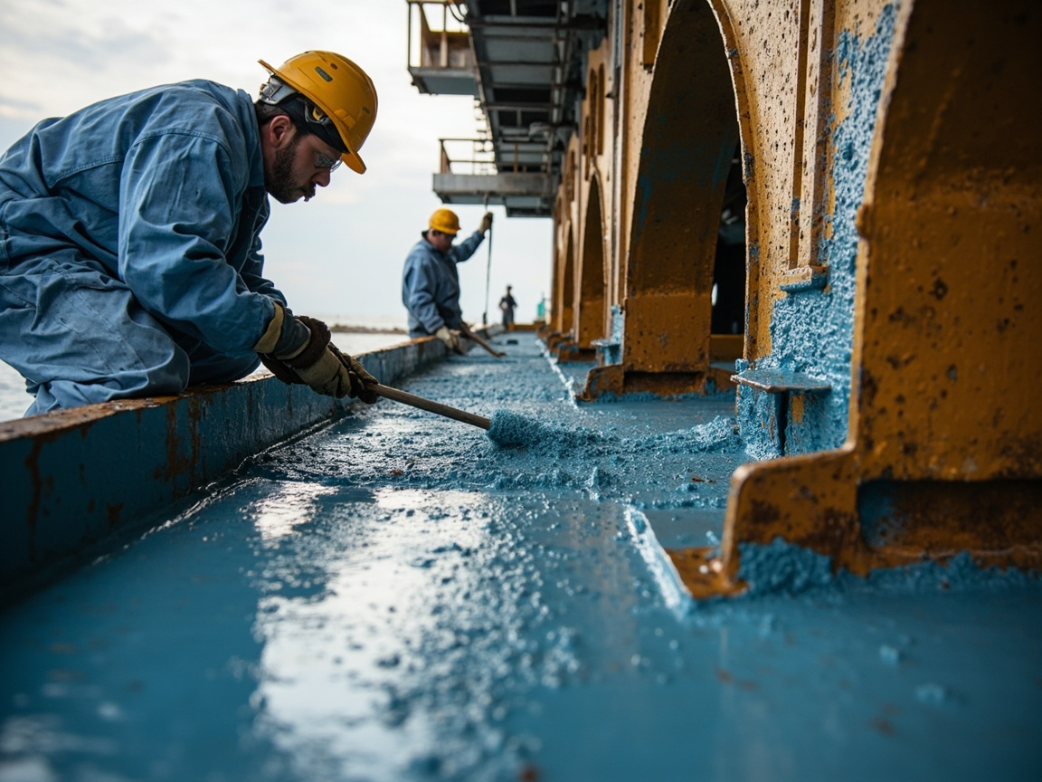
IX. Common Misconceptions and Risk List
Clarifying the most common misconceptions in engineering is more important than memorizing a bunch of parameters:
| Misconception or Risk | Actual Explanation |
|---|---|
| "Contains graphene so it must be good" | Addition level and dispersion state are key; agglomeration becomes corrosion points |
| "3000-hour salt spray conquers all" | Greatly affected by substrate, film thickness, pretreatment; same-condition comparison required |
| "Graphene paint can insulate" | Conductive type destroys insulation; strictly prohibited for insulating occasions |
| "Can fully replace zinc-rich primer" | Cathodic protection mechanism differs; low-zinc formulations must be fully validated |
| "Cheap graphene paint" | True graphene raw material costs high; low price mostly conceptual addition |
| "Thicker film means more anti-corrosion" | Excess thickness brings internal stress and cracking risk; uniformity and compatibility more critical |
In engineering decisions, it is recommended to treat "whether graphene is truly needed" as the primary question: if only routine anti-corrosion is needed, the mature system of epoxy zinc-rich plus epoxy micaceous iron oxide plus polyurethane topcoat is already sufficiently reliable and economical; only when rigid needs such as static dissipation, thin-film high shielding, or extreme lifespan emerge does graphene modification enter the cost-effective zone. For the cathodic protection mechanism of zinc-rich primer itself, see Cathodic Protection Mechanism of Epoxy Zinc-Rich Primer; for understanding the scale and characteristics of nanomaterials, refer to Overview and Classification of Nanomaterials.
X. Selection Decision Tree: Step-by-Step Judgment on Whether to Use Graphene
For specific projects, ask and answer the following in order to quickly converge on a selection conclusion:
- Does the working condition have functional rigid needs such as static dissipation, electromagnetic shielding, or auxiliary heat dissipation? No—return to traditional system (zinc-rich primer + micaceous iron oxide intermediate coat + weather-resistant topcoat) for evaluation; most scenarios end here; Yes—proceed to next step.
- Does this part require electrical insulation? Yes—prohibit conductive graphene formulation, switch to insulating functional coating route; No—proceed to next step.
- Can the supplier provide graphene layer number and quality certificates (Raman ID/IG, XRD) as well as dispersion stability data? No—reject the product; risk of conceptual addition outweighs benefit; Yes—proceed to next step.
- Are there third-party comparative test reports under same working condition, same film thickness, same pretreatment (GB/T 10125 neutral salt spray, GB/T 1410 resistance)? No—require small-batch panel comparison test first; Yes—proceed to next step.
- Does the full life-cycle cost accounting hold? Compare material premium and increased management cost from higher construction requirements against benefits from reduced film thickness and extended maintenance cycle in one table; only proceed if net benefit is positive.
The core idea of this decision tree is "functional rigid need first, data evidence as backstop, economic accounting as closure". Graphene is a plus, not a must; if any step fails, return to the mature system.
XI. Role of Electrochemical Impedance Spectroscopy (EIS) in Evaluation
Salt spray tests are intuitive but long-cycle and coarse-information; engineering increasingly uses electrochemical impedance spectroscopy (EIS) as a rapid evaluation and aging-tracking tool for the shielding performance of graphene coatings. The basic logic: immerse the coated steel plate in electrolyte (commonly 3.5 wt% sodium chloride solution to simulate seawater), apply small-amplitude sinusoidal perturbation potential, and measure impedance response at different frequencies. The low-frequency (e.g., 0.01 Hz) impedance modulus can approximate the coating's overall barrier capability against medium penetration: higher value and slower decay with immersion time indicate a denser and more stable shielding network.
For graphene-modified systems, EIS answers three questions hard to address by salt spray: first, indirect judgment of dispersion quality—well-dispersed formulations show high initial low-frequency impedance and gentle decay, while severely agglomerated ones often show early impedance drop and second time constant (corresponding to interfacial corrosion initiation); second, quantitative comparison with blank formulation—impedance difference with/without graphene under same resin and film thickness quantifies the real contribution of the labyrinth effect, not just conceptual; third, lifespan trend extrapolation—multi-cycle immersion tracking of impedance evolution can rank formulations within weeks, greatly shortening screening. Note that EIS interpretation relies on equivalent circuit fitting and experience; absolute values across labs have limited comparability. Engineering should adhere to "same-batch test, same-condition comparison", using EIS as a ranking and tracking tool, not an isolated promotional number.
XII. Failure Modes and On-Site Troubleshooting
When graphene coating problems occur in service, locate the cause against the table below:
| Failure Manifestation | High-Probability Cause | Troubleshooting Means | Disposal Recommendation |
|---|---|---|---|
| Early spot rusting | Graphene agglomeration forming defect points, local galvanic cells | Cross-section SEM observation of agglomeration, EIS premature aging | Replace with qualified dispersion batch, locally sand and patch |
| Surface resistance exceeding limit or uneven | Conductive network discontinuous, large film thickness fluctuation | Multi-point surface resistance measurement (GB/T 1410) | Recheck slurry mixing process and film thickness control |
| Large-area blistering and delamination | Insufficient pretreatment, condensation during construction | Cross-cut adhesion (GB/T 9286), dew point record | Re-blast to Sa2.5 and re-coat according to process |
| Shielding performance decays rapidly over time | Poor interfacial bonding between resin and graphene, high water absorption | EIS tracking by immersion, water absorption test | Adjust silane coupling agent modification scheme or replace resin system |
On-site troubleshooting is recommended to follow the sequence of "test electrical performance first, then inspect interface": for conductive coatings, perform multi-point surface resistance scanning first; abnormal areas often spatially coincide with dispersion or film thickness issues; then take samples from abnormal points for microscopic observation to distinguish whether it is a material batch problem or a construction process problem. Archiving the evidence chain of each failure is the basis for both suppliers and owners to continuously improve formulations and processes. In addition, for long-service storage tanks and offshore structures, it is recommended to simultaneously retain a "zero-point archive" at completion acceptance: including film thickness distribution of each zone, measured surface resistance values, adhesion data, and on-site photos. Subsequent annual inspections compare same-point re-measurement data with the zero-point archive, enabling the capture of trend changes before significant performance degradation, and moving maintenance actions ahead of failure occurrence. This is also the core method of full-life-cycle management of functional coatings.
FAQ
Q: What is the anti-corrosion mechanism of graphene coatings?
A: It mainly relies on the "maze effect" of two-dimensional flakes: corrosive media must detour around a large number of graphene flakes, the effective diffusion path is greatly extended, porosity is reduced, and shielding efficiency is improved; if the flakes form an interconnected network, they can also assist in static dissipation and heat conduction. But all this presupposes that graphene achieves monolayer, uniform dispersion in the resin.
Q: Why do some graphene paints become "worse after adding"?
A: Graphene has a large specific surface area and strong interlayer van der Waals forces, making it highly prone to agglomeration; agglomerates become defects and local galvanic cell initiation points in the coating, instead accelerating pitting. Success or failure lies in dispersion—surface modification, efficient dispersion equipment, and masterbatch pre-dispersion are all indispensable, and must be verified by SEM, XRD, Raman and other means.
Q: Can graphene coatings completely replace zinc-rich epoxy primer?
A: Simple replacement is not recommended. Zinc-rich relies on zinc sacrifice for cathodic protection, while graphene relies on physical shielding; the two mechanisms are different. A more reasonable approach is composite use (graphene + zinc) for synergistic enhancement, but low-zinc formulations must be validated by salt spray and electrochemical tests for protection margin.
Q: Are graphene coatings conductive or insulating?
A: It depends on the formulation. Graphene itself is conductive; appropriate addition can make a static-dissipative coating (surface resistance about 10⁵–10⁸ Ω); if used for energized housings requiring insulation, conductive types must be prohibited. Conductivity and insulation are contradictory requirements; clarify the electrical performance requirements of the working condition before selection.
Q: How to judge whether a graphene paint is truly effective?
A: Look at at least four pieces of evidence: first, graphene layer number and quality certification (XRD, Raman ID/IG); second, dispersion stability data (SEM, particle size distribution, Zeta potential); third, third-party neutral salt spray comparison report under same working condition (according to GB/T 10125); fourth, measured data of conductive or thermal functions. Merely labeling "contains graphene" is far from enough.
Q: How long can the salt spray performance of graphene coatings last?
A: Market claims range from 1,500 to 3,000 hours, but salt spray duration is greatly affected by substrate, pretreatment, film thickness, and coating system. Suppliers must be required to provide comparison data under same working condition and same film thickness; isolated hour numbers have no comparative meaning.
Q: What is the typical addition level of graphene in coatings?
A: Functional addition is usually at the level of 0.5% to 3% by mass fraction, building a continuous network with a small amount; excessive addition instead makes dispersion difficult, costly, and unstable. A truly effective formulation pursues "less but uniform" rather than "more addition".
Q: Which standards apply to graphene coatings?
A: For general anti-corrosion see ISO 12944, GB/T 10125 neutral salt spray, GB/T 1771 salt spray resistance; for graphene materials see GB/T 30544 terminology, GB/T 41067 and GB/T 41068 characterization and judgment (subject to the latest release); for conductivity see GB/T 1410 resistance, GB 13348 static safety. Corresponding test reports should be required for selection.
Q: Are graphene coatings suitable for battery housings?
A: If the housing requires high-voltage insulation isolation, conductive graphene would destroy insulation and is unsuitable; if the housing only needs external anti-corrosion and static dissipation, it can be considered. The need must first distinguish "insulation" and "conductive" requirements; they must not be mixed.
Q: How much more expensive are graphene coatings than traditional paints, and are they worth it?
A: Real graphene raw materials are expensive, and the comprehensive coating cost is significantly higher than zinc-rich epoxy or epoxy micaceous iron oxide. Its cost-performance ratio only holds in刚需 scenarios such as "static dissipation + high anti-corrosion" and "thin coating with long life"; in general anti-corrosion scenarios, mature coating systems are more economical.
Further Reading
- Conductive Coatings for EMI Shielding: Conductive Fillers and Shielding Effectiveness: Extends from graphene conductivity to more general conductive fillers and electromagnetic shielding coating systems.
- Cathodic Protection Mechanism of Zinc-Rich Epoxy Primer: Understand the role and boundary of zinc powder sacrificial protection in graphene composite systems.
- Overview and Classification of Nanomaterials: Recognize graphene's scale, characteristics, and characterization logic within the nanomaterial framework.
- Weather-resistant Anti-corrosion Coatings for Photovoltaic Supports: Coating Assurance for 25-Year Outdoor Service Life
- Anti-corrosion Coatings for Hydrogen Energy Storage and Transportation: Protection Challenges and Selection under High-pressure Hydrogen Environment
- Overview of Nano Coatings: Nanoparticles, Mechanism of Action, and Definition Boundaries