The ocean is one of the harshest corrosive environments for steel structures on Earth. Chloride ions (Cl⁻) in seawater have a small radius and strong penetrating power, which can destroy the passive film and induce pitting corrosion; the splash and tidal zones undergo alternating wet and dry conditions with uneven oxygen supply, forming oxygen concentration cells; the superposition of heat and humidity, microorganisms (MIC), and ultraviolet radiation causes traditional anti-rust coatings to blister and exhibit spreading rust within 3–5 years. Marine-environment nano anti-rust coatings are a new generation of solutions that, based on traditional epoxy/polyurethane systems, introduce nanoscale fillers (nano Zn, nano SiO₂, nano Fe₂O₃, nano montmorillonite, graphene, etc.) to strengthen the triple protection logic of "barrier—cathodic protection—passivation". This article expands from four aspects: corrosion mechanism, standard coordinates, nano enhancement principle, and formulation and testing, with all quantitative indicators corresponding to real standards and test methods.
Kexin New Materials (kexinMaterials) has long provided epoxy zinc-rich, micaceous iron intermediate coat, and nano-modified topcoat systems in the field of heavy-duty anti-corrosion and industrial protective coating; this article will also combine typical parameters of its marine-grade systems from publicly available technical data to help readers establish a standard-based selection judgment.
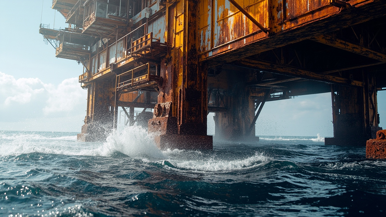
I. Specificity of Marine Corrosion and Corrosion Grade Coordinates
According to ISO 12944-2:2018 "Paints and varnishes — Corrosion protection of steel structures by protective paint systems — Part 2: Classification of environments", the marine environment can be subdivided into:
- Im1 (immersion): Permanently immersed in seawater/freshwater;
- Im2 (buried/immersed, with cathodic protection): Underwater structures with CP;
- Im3 (buried, without cathodic protection);
- C5-M (marine atmosphere/high salt spray): Coastal, deck, splash zone, the most severe atmospheric subcategory of corrosion.
Correspondingly, ISO 12944-5 provides a complete selection table from substrate treatment (Sa 2½, according to ISO 8501-1 / GB/T 8923.1) to system (primer + intermediate coat + topcoat); extreme conditions such as offshore platforms also refer to ISO 20340:2009 "Paints and varnishes — Performance requirements for protective paint systems for offshore and related structures", whose requirements for aging cycles (UV + condensation + salt spray combination) are much higher than ordinary atmosphere. For selecting marine coatings, the first step is to accurately map the "location of use" to the above coordinates, then discuss nano enhancement.
II. Triple Mechanism of Anti-Rust: Barrier, Cathodic Protection, Passivation
Whether or not containing nano, the basic logic of anti-rust coatings remains unchanged:
1. Barrier: A complete and dense paint film blocks water, oxygen, and Cl⁻ from reaching the steel substrate. Traditional micaceous iron oxide (MIO) intermediate coat relies on the flake "maze effect" to lengthen the path of corrosive media; nano fillers further lengthen this path—nano flakes/nano particles fill micron-scale pores, making the permeation path highly tortuous (tortuous path).
2. Cathodic Protection (Sacrificial): The zinc powder content in epoxy zinc-rich primer often reaches around 80% of dry film non-volatile matter (according to ISO 12944-5 and GB/T 6890 zinc powder standard); zinc is more active than iron and preferentially dissolves electrons to protect steel (according to GB/T 9793 relevant methods for zinc-rich primer). This is "electrochemical" rather than "physical" protection.
3. Passivation: Corrosion-inhibiting pigments such as zinc phosphate and molybdate form a stable passive film at the interface, inhibiting anodic dissolution. Nanoscale processing can improve their dispersion and reactivity at the interface.
The core contribution of nano anti-rust coatings is to enable these three mechanisms to synergize at a "thinner, denser, more uniform" scale—it usually does not form a separate system, but is embedded as a modifying component in epoxy primer, intermediate coat, or topcoat to enhance the long-term performance of the overall system under C5-M / Im conditions.
III. How Nano Fillers Strengthen the Barrier: From Micron Maze to Nano Maze
The shielding shortcoming of traditional coatings is that micron-scale fillers cannot seal the nano-scale micropores generated by resin curing shrinkage, and Cl⁻ can still slowly penetrate. After introducing nano fillers:
- Nano SiO₂ / Nano Clay (Montmorillonite): Flake or spherical particles fill the voids of the resin network, significantly reducing free volume and improving barrier performance under water/oxygen permeability tests (according to GB/T 1738 or equivalent cup method).
- Nano Fe₂O₃ / Nano ZnO: Combine shielding and corrosion inhibition, and the nanoscale makes the "critical" pigment volume concentration (PVC) more optimal, avoiding brittleness caused by traditional high PVC.
- Graphene/Graphene oxide: Two-dimensional flakes are almost impermeable in-plane; a small addition can greatly lengthen the water-oxygen path; however, dispersion and "local galvanic corrosion caused by cathodic shielding" are engineering difficulties requiring surface modification.
- Nano Zn: In zinc-rich primer, nano zinc has a large specific surface area and more sufficient contact, which can maintain cathodic protection current at lower zinc content, alleviating the application and brittleness problems caused by high zinc amount.
It must be emphasized: poorly dispersed nano fillers will agglomerate and instead become defect sources. What truly determines performance is the trinity of "surface modification + stable dispersion + compatibility with resin", not simply piling up nano content. Regarding the dispersion stability of nanoparticles, one may extend reading to the characterization methods of nano materials of the same batch (nmp series), which will not be expanded here.

IV. Key Standards and Test Methods: Quantifying "Anti-Rust"
Marine anti-rust coatings must pass three levels of testing, corresponding to real standards:
| Test Item | Common Standards | Description |
|---|---|---|
| Neutral Salt Spray NSS | GB/T 1771-2007 / ASTM B117 | 5% NaCl fog chamber, evaluate blistering, scribe creep (mm) |
| Cyclic Corrosion | ISO 20340 / ASTM D5895 | UV+condensation+salt spray combination, closer to real marine aging |
| Adhesion | GB/T 9286-1998 cross-cut / GB/T 5210 pull-off | Grade 0 best / pull-off strength MPa |
| Dry Film Thickness | ISO 2808 / GB/T 13452.2 | Magnetic/eddy current thickness measurement, system determines total DFT |
| VOC | GB 30981-2020 limits for industrial protective coatings | Marine heavy-duty anti-corrosion must also meet environmental red line |
According to public TDS, a qualified marine epoxy system (primer + intermediate coat + topcoat) commonly targets no blistering and controllable scribe creep in neutral salt spray 1000–3000 h; but the more stringent ISO 20340 aging cycle (usually required to pass specified cycles, e.g., 4200 h combined aging) is the "hard threshold" for offshore platform-grade products. When purchasing, be sure to distinguish "salt spray hours" from "cyclic aging hours"—the latter is more difficult and more credible.
V. Typical Marine System: Nano Path of Primer—Intermediate—Topcoat
A system validated by ISO 12944 C5-M usually looks like this:
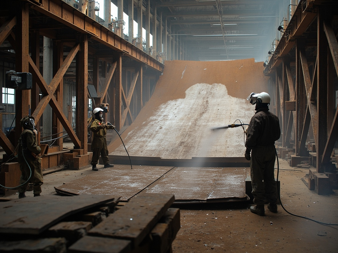
- Surface Treatment: Blast cleaning to Sa 2½ (ISO 8501-1 / GB/T 8923.1), surface roughness Ry5 40–75 µm, dust cleanliness and soluble salts (according to ISO 8502 series) controlled.
- Primer: Epoxy zinc-rich (nano Zn modified, reducing zinc dosage and improving dispersion), dry film 60–80 µm, providing cathodic protection.
- Intermediate Coat: Epoxy micaceous iron (MIO) + nano SiO₂/montmorillonite modified, dry film 100–200 µm, main barrier layer.
- Topcoat: Aliphatic polyurethane (with nano TiO₂/UV absorber against chalking) or nano-modified epoxy, dry film 50–80 µm, weather-resistant and anti-aging.
Total DFT often reaches 250–400 µm level. Nano fillers are mainly embedded in intermediate coat and topcoat to improve barrier, while primer uses nano zinc to optimize electrochemical protection. For the cathodic protection mechanism of epoxy zinc-rich, refer to the published technical article Cathodic Protection Mechanism of Epoxy Zinc-Rich Primer; for ISO 12944 system selection, read ISO 12944 Anti-Corrosion Coating System Selection Guide; for general application of nano coatings, extend reading to the same batch of Nano Coating Application Process.
VI. Engineering Trade-offs of Nano Anti-Rust: More is Not Always Better
Nano modification brings enhancement but also costs, requiring engineering trade-offs:
- Cost: Nano fillers and surface modification have high costs, and "life-cycle cost" rather than unit price should be calculated. Dispersion difficulty: Requires high-speed dispersion, sand milling, and coupling agent modification; the process window is narrow.
- Galvanic risk: Conductive nano-fillers (graphene), if unevenly dispersed, may form micro galvanic cells locally and instead accelerate pitting—uniform dispersion and insulating encapsulation must be ensured.
- Testing threshold: Conventional salt spray remains necessary after nano modification, but cyclic aging and electrochemical impedance spectroscopy (EIS) are more needed to evaluate long-term barrier attenuation.
As a system supplier, Kexin New Materials (kexinMaterials) emphasizes "standards first" in marine-grade配套: first establish a baseline using ISO 20340 cyclic aging and GB/T 1771 salt spray, then add nano-fillers incrementally in the intermediate coat/topcoat for validation, avoiding pushing unverified nano concepts directly into harsh sea areas and causing early failure.
VII. Comparison and Selection vs. Conventional Marine Coatings
| Dimension | Conventional epoxy zinc-rich + micaceous iron oxide + PU | Nano-modified marine配套 |
|---|---|---|
| Barrier densification | Good (micron labyrinth) | Better (nano labyrinth pore-filling) |
| Cathodic protection | Ensured by high zinc content (brittleness risk) | Nano zinc reduces zinc content while maintaining efficacy |
| Cyclic aging resistance | Meets conventional C5-M | Easier to pass stringent ISO 20340 cyclic test |
| Cost | Low–medium | Medium–high |
| Application process | Mature | Requires controlled dispersion / stricter surface treatment |
| Applicable | General offshore, wharf | Offshore platforms, splash zone, long-life requirements |
Selection principle: Conventional配套 is sufficient for ordinary wharves and inland bridges; the incremental value of nano-modified配套 is truly realized only for splash zones, deep-sea platforms, and projects with design life over 12 years. Do not blindly upgrade for the "nano" label.
VIII. Key Points of Application and Quality Control
70% of the success or failure of marine coatings lies in surface treatment. Key controls: ① Sandblasting Sa 2½, roughness up to standard; ② Soluble salts (chlorides) ≤ recommended limit (per ISO 8502-6 Bresle method), otherwise rust rebound is inevitable; ③ Temperature and humidity: substrate temperature 3℃ above dew point, RH ≤ 85% (ISO 12944-7); ④ Instant control of each coat's DFT with thickness gauge, total thickness up to standard; ⑤ Intercoat recoating window (per TDS, if exceeded need abrading); ⑥ Avoid direct salt spray during curing.
For general application of nano coatings (spray, dip, vapor deposition, sol-gel), further read the nano coating application process (ncl-application-process) from the same batch.

IX. Common Failures and Protection Recommendations
High-frequency failures of marine coatings: ① Rust rebound (incomplete surface treatment, excessive soluble salts); ② Blistering (insufficient barrier, water and oxygen penetration); ③ Intercoat delamination (recoating beyond window, poor adhesion); ④ Pitting (galvanic caused by uneven conductive nano dispersion). The countermeasure is the "standard + process + testing" trio: set coordinates (C5-M/Im), control surface (Sa 2½ + salt inspection), verify performance (salt spray + cyclic aging + EIS).
X. Protection Differences Among Splash Zone, Tidal Zone and Fully Immersed Zone
The weighting of corrosion mechanisms differs across marine locations, so配套 must be differentiated:
- Splash zone: Wet-dry alternation, most oxygen supply, salt deposition, sunlight UV—the most severe corrosion band. Here the barrier layer is most prone to failure from thermal expansion/contraction and salt crystallization; thickest barrier + best film-substrate bonding are required, and nano-fillers' reinforcement of the labyrinth effect has the greatest value here.
- Tidal zone: Periodic immersion + exposure, dominated by oxygen concentration cells; cathodic protection and barrier must be balanced, zinc-rich primer cannot be omitted.
- Fully immersed zone (Im1/Im2): Oxygen-deficient but persistent Cl⁻, microbial (MIC) and crevice corrosion prominent; surface treatment and defect-free application matter more than simply thickening; impressed cathodic protection (ICCP) often added.
One配套 cannot "rule them all"; the C5-M and Im classifications of ISO 12944-2 provide coordinates for this differentiation.
XI. Nano-filler Compound Example: SiO₂ + Zn + Montmorillonite
Single nano-fillers often trade off one aspect for another; engineering usually compounds them:
| Filler | Role | Compounding notes |
|---|---|---|
| Nano SiO₂ | Fill micropores, extend permeation path | Excess thickens, needs dispersant |
| Nano Zn | Reduce zinc content while maintaining cathodic protection | Prevent oxidative agglomeration, control particle size |
| Nano montmorillonite | Lamellar labyrinth, block water and oxygen | Difficult orientation arrangement, needs shear |
| Graphene (with caution) | 2D ultra barrier | Dispersion and galvanic risk |
Typical formulation logic: zinc-rich primer uses nano Zn to reduce zinc content from 80%-level to 60–70%-level while maintaining protection current; intermediate coat uses nano SiO₂ + montmorillonite to build "particle + lamellar" dual labyrinth; topcoat uses nano TiO₂/UV absorber to resist chalking. The core of compounding is not "add a bit of everything", but allocating according to each layer's failure mechanism.
XII. Service-period Testing: EIS and Pull-off Retest
Coating delivery is not the end; marine long-life relies on service monitoring:
- Electrochemical impedance spectroscopy (EIS): Through the decay of |Z|@0.01Hz over time, early warning of barrier layer water absorption and interface degradation, months to years earlier than visible blistering. Per public literature, intact barrier layer's low-frequency impedance often stays at 10⁹–10¹⁰ Ω·cm² magnitude; significant drop is warning.
- Pull-off adhesion (GB/T 5210): Periodically retest MPa, evaluate film-substrate bonding decay with salt spray/aging.
- Salt spray + cyclic aging (GB/T 1771 / ISO 20340): For new formulation validation, and in-service sampling.
As a system supplier, Kexin New Materials (kexinMaterials) recommends a "delivery baseline EIS + annual retest" mechanism for marine projects, turning protection from "one-time acceptance" into "lifecycle management".
XIII. Cost-Life Trade-off with Conventional Systems
Nano modification raises per-square-meter cost, but on full-life basis is often cheaper: fewer repairs, longer maintenance cycles, reduced downtime consequences. Ordinary wharves/inland bridges using conventional epoxy zinc-rich + micaceous iron oxide + PU is enough; for splash zones, deep-sea platforms, projects with design life over 12 years, the increment of nano modification pays back. Selection should calculate "cost per protection year" rather than "price per liter".
XIV. Electrochemical Nature of Marine Corrosion: From Anodic Dissolution to Chloride Depassivation
To make anti-rust engineering rather than experience, one must first see clearly what happens to steel in seawater. Steel corrosion is a galvanic cell process; at the anodic zone iron dissolution occurs:
Fe → Fe²⁺ + 2e⁻
At the cathodic zone in neutral oxygenated seawater, oxygen reduction mainly occurs:
O₂ + 2H₂O + 4e⁻ → 4OH⁻
The two half-reactions must proceed simultaneously with charge conservation, therefore inhibiting either side slows corrosion—this is the theoretical outlet of the triple mechanism: barrier layer blocks water, oxygen and ion channels; zinc-rich primer shifts potential making steel cathodic; inhibitive pigments form passivation film at anodic zone to suppress iron dissolution.
The special hazard of chloride lies in depassivation and autocatalytic acidification. Cl⁻ is small-radius and highly penetrating, can preferentially adsorb at passivation film defects and displace oxygen, dissolving local passivation film to form micro pits. Once a pit forms, inside is oxygen-deficient becoming anode, outside oxygen-rich becoming cathode, forming extreme unfavorable area ratio of large cathode-small anode; inside Fe²⁺ hydrolysis produces H⁺ lowering pH, further attracting Cl⁻ migration to maintain electroneutrality, forming "more corrosion more acid, more acid more corrosion" autocatalytic loop. This is why pitting silently perforates under macroscopically intact surface, and also explains why residual soluble salts are far more dangerous than visible surface rust.
Understanding this, some common phenomena are explained: why rusting at coating pinholes is far faster than whole bare steel—because extreme unfavorable area ratio; why wet-dry alternation band is most dangerous—because drying stage salt concentrates, wetting stage oxygen sufficient, both conditions met simultaneously in splash zone.
XV. EIS Interpretation Practice: Equivalent Circuit and Three Decay Stages
The reason EIS is recommended as a long-term evaluation tool is that it gives early warning months or even years before visible blistering. Implementation can refer to ISO 16773 series (electrochemical impedance spectroscopy measurement of coated metallic specimens). The core of interpretation is fitting the measured spectrum to an equivalent circuit and tracking changes of several key parameters over time:
- Coating resistance R_c: Reflects difficulty of ion passage through coating; denser barrier gives higher value.
- Coating capacitance C_c: Rises with coating water uptake, a sensitive indicator of moisture penetration, often changes earlier than R_c.
- Charge transfer resistance R_ct and double layer capacitance C_dl: Once these are distinguishable in the spectrum, it means electrolyte has reached metal interface and started corrosion reaction; barrier layer is essentially breached.
Per public literature, coating service decay usually shows three stages: Stage 1The first stage is the pure barrier period, where the low-frequency impedance modulus remains at a very high magnitude (commonly cited in the 10⁸–10¹⁰ Ω·cm² range), and the spectrum approximates pure capacitive behavior; the second stage is the water and oxygen penetration period, where C_c rises and R_c falls, but the interface has not yet reacted; the third stage is the interfacial corrosion period, where a second time constant appears, R_ct becomes distinguishable and continuously declines, and macroscopic blistering and rust spots will emerge shortly thereafter.
The practical recommendation is: perform a baseline EIS at delivery and archive it, then retest at the same location, with the same electrolyte, and over the same frequency range annually or semi-annually, comparing trends rather than absolute values. Absolute impedance measured by different laboratories or with different electrolyte concentrations cannot be compared horizontally, but the time series of the same specimen is highly informative. In addition, marine coatings should also pay attention to cathodic disbondment—at locations under applied cathodic protection, the OH⁻ generated by the cathodic reaction will saponify and destroy the adhesion at the coating-steel interface; its cathodic disbondment resistance can be evaluated according to methods such as ISO 15711 or ASTM G8 / G42, which is a failure path not covered by pure barrier property testing.
XVI. Interpretation of Standard Evolution: From ISO 20340 to ISO 12944-9
There has been an important replacement of marine anti-corrosion standards in recent years, and many technical documents still use the old name, which needs clarification:
First, ISO 20340 has been replaced by ISO 12944-9:2018. The new edition, "Paints and varnishes — Corrosion protection of steel structures by protective paint systems — Part 9: Protective paint systems and laboratory performance test methods for offshore and related structures," incorporates marine-specific testing into the main ISO 12944 system, retains the core approach of combined UV + condensation + low temperature + salt spray aging, and unifies scribing, rating, and judgment of test panels. Where technical agreements still state "compliant with ISO 20340," it should be confirmed whether the other party is executing according to the current version or following the old text.
Second, the corrosion environment classification has been adjusted. The 2018 edition merged the former C5-I (industrial) and C5-M (marine) into a unified C5, and added a more severe CX (extreme, covering offshore, high-salinity high-humidity tropical marine, etc.); the immersion categories were also expanded from Im1–Im3 to include Im4 (seawater immersed structures with cathodic protection). Therefore, "C5-M" is an old term, and current documents should use C5 or CX. The classification is based on the first-year thickness loss of low-carbon steel; there is a several-fold difference between C5 and CX, and selecting the wrong category directly leads to insufficient system grade.
Third, the durability grades have been redefined. The 2018 edition divides durability into four levels: low (L), medium (M), high (H), and very high (VH), where the very high grade corresponds to an expected first major maintenance interval exceeding 25 years. It must be emphasized that the durability grade is not a warranty period, but a design reference period; actual service life depends on construction quality and maintenance.
Fourth, domestically there is the equivalent/modified GB/T 30790 series that can be cross-referenced; citing Chinese and foreign standards side by side in engineering documents can reduce ambiguity.
XVII. Comparison of Differentiated System Design by Location
Different parts of the same marine structure differ greatly in environmental classification, failure mechanisms, and recommended practices; "applying one system all the way through" is a lose-lose in both cost and risk:
| Location | Environmental Classification Reference | Dominant Failure Mechanism | System Key Points |
|---|---|---|---|
| Atmospheric zone (upper structure) | C5 / CX | UV aging, salt spray deposition, chalking and gloss loss | Zinc-rich primer + epoxy intermediate coat + aliphatic polyurethane topcoat, heavy weather resistance |
| Splash zone | CX (most severe) | Wet-dry alternation, sufficient oxygen, mechanical impact | Thicken barrier layer, glass flake or high-solid epoxy, encapsulation if necessary |
| Tidal zone | CX / Im | Oxygen concentration cell, periodic immersion | Equal emphasis on barrier and cathodic protection, zinc-rich primer indispensable |
| Full immersion zone | Im2 / Im4 | Anoxic but continuous Cl⁻, crevice corrosion, MIC | Defect-free construction priority, combined with external cathodic protection, requires cathodic disbondment resistance |
| Submud zone | Im3 | Anaerobic, sulfate-reducing bacteria | High-build epoxy, focus on MIC and mechanical damage prevention |
| Inside tanks / ballast tanks | Im class | Alternating empty/full, condensation, cleaning abrasion | Light-colored epoxy for easy inspection, strict control of film thickness uniformity |
Key points for reading the table: the technical routes for the splash zone and full immersion zone are opposite in direction. The enemy of the splash zone is oxygen and mechanical impact, won by "thick and tough"; the enemy of the full immersion zone is continuous ion permeation and cathodic disbondment, won by "dense and defect-free, alkali and disbondment resistant"—blindly thickening instead increases internal stress and cracking risk. The value of nano fillers also differs in the two locations: the former mainly improves barrier and impact resistance, the latter mainly reduces ion permeability and improves interfacial stability.
XVIII. Microbiologically Influenced Corrosion and Crevice Corrosion: Two Easily Overlooked Paths
Microbiologically influenced corrosion (MIC) is particularly prominent in anaerobic or semi-anaerobic environments such as marine mud, ballast tanks, and pipeline interiors. Sulfate-reducing bacteria (SRB) reduce sulfate to sulfide under anoxic conditions, both directly consuming hydrogen on the cathode to accelerate anodic dissolution, and generating corrosive sulfides and forming a local micro-environment under the biofilm. The typical morphology of MIC is a hemispherical pit with steep edges and a bright inner wall, which can be preliminarily distinguished from ordinary pitting by morphology and sulfide residues. In protection, note: in anaerobic environments with SRB, the protection potential of steel needs to be more negative than conventional, which increases cathodic disbondment pressure; therefore the coating's cathodic disbondment resistance must be improved simultaneously, otherwise "the more thorough the protection, the faster the coating disbonds."
Crevice corrosion occurs in narrow gaps such as flange faces, under bolt washers, overlapping welds, and support contact surfaces. After the solution inside the crevice stagnates and oxygen is depleted without replenishment, an occluded cell similar to pitting forms, with acidification and Cl⁻ enrichment also self-catalyzing. The engineering countermeasure lies not in coatings but in design and construction: preferably use continuous welding instead of overlap, avoid dead corners and water accumulation blind spots, and use sealant or stripe coating at crevices. Stripe coating is the highest-return yet most often omitted process in marine painting—at complex geometries such as welds, edges, and bolts the film naturally thins; pre-applying a coat by brush yields far more protection than spraying an extra 20 µm on flat surfaces.
XIX. Coating Rating, Maintenance Grading, and Repainting Decisions
Condition evaluation of in-service coatings should use a unified rating language, avoiding unarchivable descriptions like "okay" or "a bit rusty." The internationally accepted practice is to rate separately according to the ISO 4628 series: blistering (quantity and size), rusting (percentage of rusted area), cracking, and flaking are each rated independently, with a method for measuring the width of creepage from scribe lines; the US standard system commonly uses ASTM D610 (rust grade) and ASTM D714 (blister grade). Rating results directly correspond to maintenance strategy:
- Local repair (spot repair): Rust area is very small and scattered; after treatment to specified cleanliness, locally patch coat and blend with surrounding area. Applicable to early isolated defects, lowest cost.
- Zone repair: Defects are dense in a certain area but overall still acceptable; derust that area entirely and redo the system.
- Full recoat: Defect area exceeds threshold or coating is overall aged and chalked with generally reduced adhesion; at this point the edges of local repairs keep generating new disbondment, and continued patching is wasteful.
To judge when to shift from "repair" to "recoat," besides area ratio, one should also look at residual adhesion (quantified by pull-off per GB/T 5210 / ISO 4624) and EIS trend. If the pull-off values have generally dropped below half of baseline, or low-frequency impedance has entered the third stage, even if appearance is still acceptable, an overall recoat plan should be prepared. The most expensive part of a marine project is not the coating, but scaffolding, shutdown, and offshore operation windows; therefore the decision value of maintenance timing often exceeds the selection of the coating itself.
XX. Marine Anti-Corrosion System Selection Decision Tree
Step 1 · Locate environmental coordinates. Determine per current ISO 12944-2 classification whether each location belongs to C5, CX, or Im1–Im4; do not沿用 the old C5-M expression and ignore the existence of CX.
Step 2 · Set durability grade and first major maintenance interval. Clarify whether it is M, H, or VH; this determines the system grade and total dry film thickness, and also whether acceptance testing follows ISO 12944-6 routine or ISO 12944-9 marine specific.
Step 3 · Determine whether cathodic protection is superimposed. If ICCP or sacrificial anodes are present, cathodic disbondment resistance requirements must be added (ISO 15711 type methods), otherwise the interface will saponify and disbond under protection current.
Step 4 · Verify surface treatment achievability. Workshop can achieve Sa 2½ or even Sa 3; field repair may only achieve power tool cleaning grade; the system must match the actually achievable cleanliness, not the ideal value.
Step 5 · Evaluate whether nano modification is truly needed. For conventional locations and conventional life requirements, a mature zinc-rich + micaceous iron + polyurethane system is sufficient; only in splash zone, CX environment, VH durability requirements, or scenarios where maintenance windows are extremely expensive does the incremental cost of nano modification pay off.
Step 6 · Cure acceptance checklist. Surface cleanliness and roughness, soluble salts, per-coat and total dry film thickness, adhesion, appearance rating, and baseline EIS. Any missing item is a foreshadowing of later disputes.
XXI. Marine Anti-Corrosion Standard Quick Reference Table
| Phase | Standard Number | Purpose Description |
|---|---|---|
| Environmental classification and durability | ISO 12944-2 / GB/T 30790.2 | C1–C5, CX, Im1–Im4 classification and durability grades |
| System selection | ISO 12944-5 / GB/T 30790.5 | Recommended systems and total DFT for each corrosion class |
| Laboratory performance testing | ISO 12944-6 | Laboratory verification of conventional environment systems |
| Application and supervision | ISO 12944-7 | Environmental conditions, process control requirements |
| Specification preparation | ISO 12944-8 | Framework for writing technical specifications |
| Offshore specialized testing | ISO 12944-9 (formerly ISO 20340) | UV + condensation + salt spray combined aging, offshore platform threshold |
| Surface preparation grade | ISO 8501-1 / GB/T 8923.1 | Blast cleaning grades such as Sa 2½, Sa 3 |
| Surface roughness | ISO 8503-2 | Comparative replica method for assessing anchor pattern depth |
| Surface dust content | ISO 8502-3 | Tape method for assessing dust grade |
| Soluble salts | ISO 8502-6 / ISO 8502-9 | Bresle sampling and conductivity method quantification |
| Dry film thickness | ISO 2808 / ISO 19840 / GB/T 13452.2 | Film thickness measurement and judgment rules on rough surfaces |
| Adhesion (pull-off) | GB/T 5210 / ISO 4624 | Quantitative MPa, core indicator for in-service retesting |
| Adhesion (cross-cut) | GB/T 9286 / ISO 2409 | Quick screening |
| Neutral salt spray | GB/T 1771 / GB/T 10125 / ISO 9227 / ASTM B117 | Accelerated corrosion resistance preliminary screening |
| Aging rating | ISO 4628 series / ASTM D610 / ASTM D714 | Itemized rating of blistering, rusting, cracking, flaking |
| Electrochemical impedance spectroscopy | ISO 16773 series | Early warning of barrier property decay |
| Cathodic disbondment resistance | ISO 15711 / ASTM G8 / ASTM G42 | Mandatory test for cathodically protected areas |
| VOC limits | GB 30981-2020 | Eco-friendly red line for industrial protective coating |
It is recommended to reference the above table in technical agreements by the five segments of "environment coordinates — surface preparation — system and film thickness — acceptance testing — in-service monitoring", and annotate the version year for each item. Ninety percent of disputes in marine projects stem from inconsistent acceptance criteria, not from the coating itself being unqualified.
FAQ
Q: Why is corrosion in marine environments so much faster than inland?
A: The main reason is that Cl⁻ has a small radius and strong penetrating power, destroying the passive film and inducing pitting; the splash zone's alternating wet and dry conditions form an oxygen concentration cell; coupled with heat and humidity, microorganisms, and UV. ISO 12944-2 classifies high-salt-spray coastal areas as C5-M, and marine immersion as Im class, with corrosion grades far higher than C3/C4 inland.
Q: Is nano filler a substitute for epoxy zinc-rich?
A: No. Nano fillers mainly reinforce the "barrier" layer (intermediate coat / topcoat), while the "cathodic protection" provided by epoxy zinc-rich primer still relies on zinc; nano Zn only makes cathodic protection more efficient at lower zinc content. The two are complementary in the system, not a substitute.
Q: Is 3000 h of neutral salt spray sufficient to demonstrate marine durability?
A: Not enough. GB/T 1771 / ASTM B117 salt spray is necessary but coarse acceleration, not covering UV and wet-dry cycling. Offshore platform level should refer to ISO 20340 combined aging (UV + condensation + salt spray), which is closer to the real sea area, with higher thresholds and more credibility.
Q: Is adding graphene to anti-rust paint definitely better?
A: Not necessarily. 2D graphene has extremely strong water and oxygen barrier, but uneven dispersion can form local micro-cells and induce pitting; and its conductivity may interfere with cathodic protection current distribution. Surface modification, uniform dispersion, and controlled dosage are mandatory, and validation by EIS and salt spray is required, rather than blind addition.
Q: Why does surface preparation emphasize soluble salts?
A: In seawater environments, chloride ions remain in the pits of blasted steel plates; even with intact coating, salt crystallization absorbing water can push up blisters under the film and induce filiform corrosion. The ISO 8502 series (Bresle method) detects and controls soluble salts, an indispensable step for marine coating.
Q: Nano anti-rust coating is more expensive, is it worth it?
A: Depends on the working condition. Ordinary docks and inland bridges using conventional systems (epoxy zinc-rich + micaceous iron oxide + PU) have better cost-performance; for splash zones, deep-sea platforms, and projects with design life over 12 years, the incremental value of nano modification in cyclic aging and long-term barrier pays off. Calculate by whole-life cost, not unit price.
Q: How to test whether nano modification is actually effective?
A: In addition to conventional salt spray (GB/T 1771) and adhesion (GB/T 9286 / GB/T 5210), it is recommended to add ISO 20340 cyclic aging and electrochemical impedance spectroscopy (EIS) — EIS can early reveal water/oxygen permeation and interface degradation of the barrier layer, warning earlier than visible blistering.
Q: How thick should the total dry film thickness generally be?
A: Marine heavy-duty anti-corrosion systems often have total DFT of 250–400 µm: zinc-rich primer 60–80 µm + micaceous iron oxide intermediate 100–200 µm + topcoat 50–80 µm. Specifically determined by ISO 12944-5 selection table and corrosion class; not the thicker the better, but must meet the standard and be uniform.
Q: What are the main roles of nano SiO₂ and nano montmorillonite?
A: They use flake/spherical nanoparticles to fill the nano micropores generated by resin curing shrinkage, lengthening the penetration path of corrosive media (tortuous path), significantly enhancing the barrier. They belong to "passive barrier" enhancement, do not conflict with zinc's cathodic protection, and can be safely stacked.
Q: What are the hard requirements for temperature and humidity during application?
A: According to ISO 12944-7, substrate temperature should be at least 3℃ above dew point, relative humidity usually ≤ 85%, to avoid condensation causing intercoat adhesion failure; offshore sites should also avoid the curing period of direct salt spray. Temperature and humidity are the invisible threshold for marine coating adhesion and durability.
Further Reading
- Cathodic protection mechanism of epoxy zinc-rich primer: Understand the foundation of "electrochemical protection" in marine anti-rust, and clarify the relationship between zinc sacrificial anode and nano zinc modification.
- ISO 12944 anti-corrosion coating system selection guide: Apply corrosion classes (C5-M/Im) to complete primer—intermediate—topcoat systems and DFT design.
- Nano coating application process: From blasting, spraying to sol-gel, establish a reproducible application and QC framework for nano-modified coatings.
- Electronic device nano protective coating: conformal, hydrophobic and PCB-level reliability
- Food-grade nano contact coating: regulations, migration safety and nano additive boundaries
- Nano coating overview: nanoparticles, mechanism and definition boundaries