Abrasion- and stone-chip-resistant coating systems for commercial vehicle bodies and trailers means systems designed for truck cargo boxes, tipper bodies, trailer chassis and wheel arches, built as heavy-duty anticorrosion primer plus a high-build or elastic intermediate layer plus an abrasion-resistant topcoat (or one continuous elastic membrane): they have to resist abrasive wear (ore fines, grain and sand rubbing repeatedly along the body slide plates), high strain-rate impact (dropped cargo, ricocheting gravel, stones thrown up by the vehicle in front) and the chemo-mechanical coupling of high-pressure water/steam washing with de-icing salt spray. The acceptance language for this class of system is not the pencil hardness and scratch resistance normally used for automotive clearcoats, but auditable Taber wear values (mg/1000 cycles), ISO 20567 stone-chip ratings, pull-off adhesion (MPa) and the ISO 12944 film-build-to-salt-spray combination.
A tipper comes back to the shop for acceptance after its first coal-hauling season: on the inside of the box a bright worn stripe about a hundred metres long has been polished along each side of the slide plates, with primer exposed in places; on the coating of the lower side rails and the wheel arches the stone-chip craters run into one another and orange rust spots are starting to appear at their rims; on the chassis longitudinal rails the coating has blistered at the weld toes after repeated jet-washing. The loss is then three separate bills: repair welding and downtime caused by steel worn through, rework and repainting that consume operating windows, and structural inspection brought forward by corrosion. Fleet purchasers nevertheless often specify a truck body paint using the "hardness" vocabulary of automotive clearcoat - between the two vocabularies sits an entire set of test methods and pass/fail logic, and pinning each of these down item by item is exactly what this article does.
TL;DR: conclusions first
- The load spectrum is three superimposed mechanisms, not a single "abrasion" figure. Abrasive wear in the body slide-plate zone maps to Taber-type metrics (GB/T 1768 / ASTM D4060); lower side rails and wheel arches map to stone-chip metrics (ISO 20567-1:2017 / SAE J400); and the whole vehicle maps to the "washing + salt spray + mechanical" coupling. Accepting a body paint on hardness or scratch resistance alone selects a formulation that fails simultaneously in two directions: stone-chip crater growth and wet abrasive wear.
- Wear has to be written as mass loss before it becomes a criterion. Rotary rubber wheel method: CS-10/CS-17 wheels, per-wheel loads commonly 500-1000 g, turntable (60±2) r/min, results reported as mg/1000 cycles or as cycles to wear-through; order-of-magnitude reference from publicly summarised testing: polyurethane topcoat about the 20 mg/1000 cycles level, epoxy MIO intermediate about 60 mg/1000 cycles, epoxy zinc-rich primer about 80 mg/1000 cycles (mutually comparable only under identical conditions).
- The primary stone-chip criterion is the three-part ISO 20567 series. Part 1 (2017 edition) is the multi-impact test: chilled cast-iron grit 3.55-5.00 mm, 54° incidence, nozzle-to-panel distance about 290±1 mm, test pressure in two settings of 100 kPa and 200 kPa, damage area rated on the 0.5 to 5.0 scale; Part 2 (2023 edition) and Part 3 are single-impact tests. North American practice commonly uses SAE J400/ASTM D3170: gravel 9.5-15.9 mm, about 483 kPa, 90° impact.
- High-build systems can only be checked by the pull-off method. GB/T 5210-2006 (identical to ISO 4624:2002) reports an MPa value plus the failure mode; the cross-cut test GB/T 9286-2021 does not apply to coatings above 250 µm total dry film thickness, ASTM D3359 cross-cutting covers only less than 125 µm, and thicker films use the X-cut method (GB/T 31586.2). Published verification wording for ISO 12944-6: every pull-off point not less than 2.5 MPa, and no adhesive failure at the interface between the first coat and the steel (unless the break strength is not less than 5 MPa).
- State the corrosion backbone in ISO 12944 language. Durability ranges L is not above 7 years, M 7-15 years, H 15-25 years, VH above 25 years; published system tables state that for a C4 environment total film thickness is about 160-280 µm depending on durability range, and engineering salt-spray durations commonly used in tenders (GB/T 10125-2021 / ISO 9227:2017 neutral salt spray) are C3 480 h, C4 720 h, C5 1440 h.
- Choose the route by takt time and rework mode. PVC plastisol reaches about 95% solids and above, typical underbody membrane 1-2 mm, and it needs fusion at not less than about 140 °C for about 30 min, which suits an oven-equipped serial line; moisture-cure polyurethane and solvent-free polyaspartic (PAE) cure at ambient temperature - published literature comparisons give PAE adhesion to Q235 steel of 11.32-13.95 MPa, still 10.02-12.56 MPa after stone impact, while PVC under the same conditions is about 2.27 MPa; discharge efficiency is read through the coefficient of friction: UHMWPE liner panels have a published static friction coefficient of about 0.05-0.11, and the recommended discharge angle can drop from about 48° for wear-resistant steel plate (NM400 grade) to around 32°.
1. The commercial-vehicle load spectrum: three mechanical loads acting at once
The design inputs for a passenger-car coating are "high-speed stone chips + car washing + weathering". A commercial vehicle has to answer three additional questions: its coating surface is held under abrasive contact by bulk material for long periods, is struck whole by dropped cargo, and is hosed with water carrying salt at the same time. The three load classes fail by different mechanisms, call for different tests and criteria, and mixing one set of metrics across them inevitably leads to a wrong judgement.
1.1 Abrasive wear: how the bright stripe on the slide plate forms
When a tipper carries ore fines, coal or aggregate, tonnes upon tens of tonnes of material sit on the floor plate, and the vibration of the vehicle in motion keeps the particles rolling and sliding across that surface - a textbook case of three-body abrasive wear under normal load. The variables that set the wear rate are abrasive hardness and angularity, contact pressure, sliding distance, and the coating's own resistance to micro-cutting; hard minerals (quartz sand, iron-ore fines) are especially damaging to organic coatings because the abrasive is generally harder than the resin matrix. Grain-type media carry softer abrasives, but long-term grinding combined with the scraping of discharge turns the failure mode into polishing and gloss loss with gradual thinning. The side panels take one more form of wear: buckets and shovels gouging the panel surface during loading and unloading. Slide-plate liners (UHMWPE/HDPE) act as the sacrificial element and absorb this layer of wear, at which point the coating system's role becomes protecting the steel beneath the liners and rust-proofing bolt holes and panel joints.
1.2 Impact: dropped cargo and thrown stones differ by an order of magnitude in strain rate
Dropped-cargo impact is "large mass, low velocity, single high-energy event" - a bucket of waste rock falling two or three metres onto the floor plate. Stone throwing is "small mass, high velocity, repeated low-energy events" - gravel picked up by the tyres of the vehicle in front striking the wheel arches and lower side rails at tens of kilometres per hour. Their failure modes differ too: the first tests the ability of coating and substrate to deform together (cracking of the membrane, chipped edges of a brittle primer), the second tests intercoat adhesion and crack-propagation resistance in a multilayer system (stone-chip craters growing into sheets, delamination between coats). In engineering practice, falling-weight type tests (GB/T 1732, published wording: a 500 g/1000 g steel ball dropped from 100 cm, with no cracking and no detachment of the film) assess the first and stone-chip tests assess the second; neither substitutes for the other.
1.3 Chemo-mechanical coupling: high-pressure washing plus de-icing agents
Fleet maintenance commonly washes bodies and chassis with high-pressure water or even hot water; in northern winters de-icing agents (sodium chloride/calcium chloride types) enter weld seams, hemmed edges and wheel-arch cavities with the slush, and washing drives that salt into coating defects, after which moisture and chloride ions act continuously at impact craters and scratches - a coupling of "hydraulic penetration + electrochemical corrosion + mechanical flushing". This duty is structurally the same coupling as the "high-pressure washing + ammonia corrosion" case in our livestock-building article (see Livestock building steel corrosion protection: ammonia, high humidity and coating systems), so acceptance has to test "adhesion and salt-spray resistance after ageing/impact", not only fresh panel data.
1.4 Why passenger-car clearcoat metrics are not enough: the toughness-hardness balance and the high-build elastic layer
The evaluation anchors of a clearcoat system are hardness, scratch resistance and orange-peel/distinctness of image, buying scratch resistance with high crosslink density; what the commercial-vehicle load spectrum requires is energy dissipation: the stress wave an impact generates inside the coating must be dissipated by large deformation above the glass-transition region, while abrasive cutting requires the surface to have enough load-bearing stiffness not to let the particle embed too deeply. A single resin layer rarely satisfies both ends, so the engineering answer is to split the layers: a high-build elastic layer (PVC plastisol, polyurea, highly elastic polyurethane intermediate) takes the impact dissipation, and an abrasion-resistant face layer (highly crosslinked polyurethane/polyurea topcoat, or a sacrificial liner) takes the abrasive cutting. Low temperature is the touchstone of this logic: once the service temperature falls below the coating's glass-transition region the elastic layer turns brittle and the stone-chip rating deteriorates markedly - which is precisely why vehicle makers write low-temperature conditioning into their stone-chip tests (see Section 3).
2. Quantified abrasion criteria: the Taber rotary rubber wheel method and the falling-sand method
The main battleground for organic-coating abrasion is the rotary rubber wheel method (Taber type). The national standard GB/T 1768, Paints and varnishes - Determination of abrasion resistance - Rotary rubber wheel method (Taber type), adopted ISO 7784-2:1997 identically in its 2006 edition and was revised and re-issued in 2020 (details of the current edition are governed by the standard text itself); ASTM D4060 (current edition re-approved in 2025) is close in content to ISO 7784-2:2023 but not technically fully equivalent. The instruments and operating parameters of both are given in the table below.
| Item | GB/T 1768 (2006 edition text) | ASTM D4060 |
|---|---|---|
| Abrasive wheels | Rubber wheels CS-10F/CS-10/CS-17 (Taber designations), thickness (12.7±0.1) mm, new-wheel outside diameter (51.6±0.1) mm, scrapped when the outside diameter reaches 44.4 mm | CS-10 or CS-17 (the more aggressive one); other wheel types by agreement between the parties; wheel width (12.7±0.3) mm, minimum outside diameter 44.4 mm |
| Load | Weight combinations applied per wheel, nominal mass up to 1 kg | Stepped loading of 250 g/500 g/1000 g per arm; the standard recommends 1000 g |
| Speed | Turntable (60±2) r/min | Turntable 72±2 r/min (60 Hz machines) or 60±2 r/min (50 Hz machines) |
| Wheel dressing | Dressed before each test and after every 500 cycles of running with the dressing medium (P180 sandpaper disc), typically for 50 cycles | Dressed before the test and for 25-50 cycles with S-11 (150 mesh) paper after every 500 cycles |
| Specimens and environment | 100 mm×100 mm or Ø100 mm, centre hole 6.35 mm; (23±2) °C / (50±5)% RH, conditioning for not less than 16 h; 3 parallel specimens averaged | Ø100 mm or 100 mm square panels, centre hole 6.5 mm, thickness not greater than 6.3 mm, not fewer than 2 specimens; conditioning at the same temperature and humidity for not less than 24 h |
| Dust extraction | Twin vacuum nozzles, 1-2 mm from the panel surface, pressure inside the enclosure 1.5-1.6 kPa below atmospheric | Nozzle (3±1) mm from the panel surface, suction setting 100 (about 13.7 kPa) |
| Expression of results | Mass loss after the specified number of cycles (mg, to a resolution of 1 mg), or cycles worn through to the next coat/substrate; balance readability 0.1 mg | Wear index (A−B)×1000/C, i.e. mg/1000 cycles; or cycles per mil to wear-through, or cycles to failure |
| Instrument verification | Zinc plate plus P180 sandpaper strips, 500 g load run for 500 cycles; the mean loss of three runs shall be (110±30) mg | Seven-laboratory round robin of 2006: for the example epoxy coating, repeatability limit r = 8.7 mg and reproducibility limit R = 43.0 mg |
2.1 How to read the results: condition binding and system ranking
Taber data are only comparable across the board under "same wheel type, same load, same number of cycles, same cure age" - change the wheel type and the whole dataset can shift. The order-of-magnitude reference from publicly summarised testing under identical conditions (CS-10 or CS-17, 1000 g, 1000 cycles) is: epoxy zinc-rich primer about 85 mg/1000 cycles, epoxy MIO intermediate about 62 mg/1000 cycles, polyurethane topcoat about 22 mg/1000 cycles, modified epoxy topcoat about 18 mg/1000 cycles; the container-coating industry standard JT/T 810-2011 sets a published figure for interior coatings of not more than 25 mg wear at CS-10 wheel, 1000 g, 1000 cycles, and exterior coatings carry a separate requirement for wear retention after 600 h of UV ageing. When you set the acceptance line for a body topcoat, write the triple "target area - test condition - limit value" into the technical agreement, for example "CS-17 / 1000 g / 1000 cycles, wear not greater than 40 mg/1000 cycles, and post-wear cross-cut adhesion in the same class as before wear".
High-build and lining coatings also commonly use the falling-sand method (GB/T 23988-2009, Paints and varnishes - Determination of abrasion resistance - Falling sand method / ASTM D968): standard quartz sand of 0.5-1.0 mm dropped from a height of 500 mm onto a panel held at 45°, reported as litres of sand per unit film thickness worn through (L/mm) - it is closer to the "sand scouring" duty but cannot be converted into or out of Taber data. Our other articles on the abrasion-test family are Nanocoating abrasion and hardness testing: pencil hardness, Taber and scratch and Wear-resistant powder coatings: hard fillers, wear mechanisms and duty-based selection.
3. Quantified stone-chip criteria: the ISO 20567 series and the North American gravel method
A stone-chip test rates the composite resistance of the whole coating system: the toughness-hardness match between face and backing layers, intercoat adhesion, and the energy dissipation of the high-build layer. ISO 20567, Paints and varnishes - Determination of resistance to stone chipping, has three parts: Part 1 is the multi-impact test (ISO 20567-1:2017, published in 2017 in replacement of the 2005 edition, the method deriving from the German DIN 55996 family); Part 2 is the single-impact test with a guided projectile (current 2023 edition); Part 3 is the single-impact test with a free-flight projectile (ISO 20567-3:2012). It should be stated that the current Chinese national standard system has no converted stone-chip equivalent (the domestic gravel-impact method for automotive wheels was only registered for development as a group standard in 2023 to fill that gap), so commissioned testing is normally carried out to ISO 20567-1, SAE J400, ASTM D3170 or the vehicle maker's own specification.

| Item | ISO 20567-1:2017 (multi-impact) | SAE J400 / ASTM D3170 (gravel method) |
|---|---|---|
| Impact medium | Chilled cast-iron grit (to ISO 11124-2), particle size 3.55-5.00 mm, about 500 g per run, reuse limited to 100 uses | Natural gravel/cobbles 9.5-15.9 mm (3/8 to 5/8 in), about 473 mL (1 pt) per cup, with a 2 pt setting as well |
| Air pressure | Two settings of 100 kPa and 200 kPa (±10 kPa), combined with the number of projectiles into methods A/B/C (published secondary accounts give two versions of which pressure belongs to A and B, so the method number must be confirmed with the laboratory when ordering the test) | About 483 kPa (70 psi); verification reports commonly use 480±20 kPa |
| Geometric conditions | Incidence angle 54° (published secondary wording 54±1°), distance from panel to nozzle centre 290±1 mm, acceleration tube inside diameter 30±0.2 mm and length 352±2 mm, pressure-chamber volume not less than 90 L | Nozzle-to-specimen distance adjustable in the 100 mm range, impact angle 90° (some instruments support 45°) |
| Conditioning | (23±2) °C / (50±5)% RH for not less than 16 h (ISO 3270) | Can be conditioned in steps at room temperature, about 5.6 °C and about -29 °C (-29±3 °C being common) |
| Assessment | After removal of loose material, the damage area is compared with the rating chart and a class between 0.5 and 5.0 is assigned (each half class a step; published secondary wording gives class 1.0 as roughly 1.0% damage area, class 3.0 as roughly 19.2%, class 5.0 as roughly 81.3%); optical imaging to ISO 21227-2:2006 may also be used; published precision figures are r = 0.5 class and R = 1.0 class | After lifting loose coating with tape, the number and size of detached craters are counted and rated against the standard charts (example verification data: 8-9 class at room temperature, falling to 5-7 class in the -35 °C group) |
3.1 Single-impact settings and how to word the acceptance line
ISO 20567-2:2023 (single impact with a guided projectile) strikes the coating once with a wedge-shaped hardened-steel projectile confined in a tube, measures the total width of detachment after impact, and moves the panel about 20 mm between successive impacts to avoid overlap; the published secondary precision figures are a repeatability limit r of about 1.4 mm and a reproducibility limit R of about 2.2 mm. Part 3 is the single-impact method with a free-flight projectile. The multi-impact setting (Part 1) simulates "long-term driving on gravel roads", while the single-impact settings (Part 2/3) come closer to the extreme event of "one stone hitting once". In a technical agreement, write the four elements "method number + setting + temperature condition + acceptance class", for example "to ISO 20567-1 method C, conditioned at room temperature, rating not worse than class 1.5; plus one further setting conditioned at -20 °C". On the passenger-car side, see Anti-chipping nano impact-resistant chassis coating and Corrosion validation of automotive alloy wheel coatings: salt spray, stone chip and pressure-wash comparison; the "salt spray + stone chip + pressure wash" combination logic of the latter is exactly the same as for trailer wheel arches.
3.2 OEM specification families and low-temperature embrittlement
At vehicle-maker level, the publicly known stone-chip specification families include Volkswagen PV 1213, General Motors GMW 14668, Ford FLTM BI 157 series, Chrysler 463PB series, Nissan, Toyota and the German TL 211 among others (equipment makers' published compatibility lists); the parameters are all corporate standards and must be requested from the vehicle maker. Why low temperature must be listed separately: resin coatings enter the glassy state at low temperature, the impact energy can no longer be dissipated by large deformation, and stone-chip damage changes from "point-wise dents" to "sheet-wise detachment". The graded temperature conditioning of SAE J400 (room temperature / about 5.6 °C / about -29 °C) and the -20 °C stone-chip step required by some European specifications exist precisely to quantify that transition. Commercial-vehicle service conditions (northern winters, day-night swings in mining areas) normally call for at least one additional low-temperature stone-chip setting.
4. Adhesion and high-build systems: the pull-off MPa criterion and the limits of the cross-cut test
Total film thickness on body and trailer systems is commonly in the 250-500 µm band (engineering wording, depending on the corrosion protection class and reinforcement in the slide-plate zone), and at high build the cross-cut test has already gone out of scope: GB/T 9286-2021 (adopting ISO 2409:2020 identically) explicitly does not apply to coatings with a total dry film thickness greater than 250 µm; the cross-cut method (Method B) of ASTM D3359 is scoped to total film thickness below 125 µm, above which the X-cut method (Method A) is used instead; for high-build systems the national-standard acceptance route is GB/T 31586.2-2015 (corresponding to the ISO 16276 series of cross-cut and X-cut assessment) and GB/T 31586.1-2015 (pull-off).
| Item | Published wording (standards and testing material) |
|---|---|
| Pull-off method and reporting | GB/T 5210-2006 (IDT ISO 4624:2002; the current converted ISO 4624 editions have reached 2016/2023) - results are written as "break strength in MPa + percentage failure area + failure-type code" (substrate cohesive / interfacial adhesive / coating cohesive / intercoat / adhesive layer); the loading-rate ceiling is about 1 MPa/s and the force should reach failure within about 90 s |
| Verification threshold (corrosion-protection systems) | Published wording of the ISO 12944-6 verification system: strength at every pull-off point not less than 2.5 MPa, and no adhesive failure allowed at the interface between the first coat and the steel (or metallised layer) - unless the strength at that point is not less than 5 MPa; engineering tenders commonly take 3-5 MPa |
| The correct use of the cross-cut test | A rapid screen at total film thickness not greater than 250 µm (the class 2 or better judgement); at high build the cutter spacing no longer matches the film thickness, so "not cut through" is misread as "good adhesion" or edge chipping is misread as "poor adhesion" |
| Between coats, edges and corners | Inter-coat flash-off per the TDS window; after stripe coating of edges and weld seams, pull-off sampling shall include the weld toes among the test locations, so that flat surfaces pass while edges and corners stay within scope |
Published examples of film-build and coat-count allocation (typical prescriptive wording of GB/T 30790.5 / ISO 12944-5 systems): a C4 high-durability three-coat system - one coat of epoxy zinc-rich primer at 70-80 µm, one coat of epoxy MIO intermediate at 100-120 µm, two coats of polyurethane topcoat at 40-50 µm each, totalling 250-300 µm. A body system builds on that by replacing the intermediate layer with an epoxy glass-flake high-build coat or adding coats of elastic intermediate (the maze-like barrier mechanism of out-of-plane glass-flake orientation and the application window are covered in Epoxy glass-flake high-build coating: barrier mechanism of heavy-duty anticorrosion linings and application window); the system-design logic is set out in Antirust coating system design: primer-intermediate-topcoat layers and ISO 12944 film-thickness allocation.
5. Corrosion-protection system: matching ISO 12944 film build, durability range and salt-spray duration
For complete commercial vehicles and trailers it is more efficient to organise acceptance in structural-steel coating language: ISO 12944-1:2018 defines the durability range as "the time before first major maintenance" (not a warranty period) - low (L) not exceeding 7 years, medium (M) 7-15 years, high (H) 15-25 years, very high (VH) above 25 years; first major maintenance is deemed due when about 10% of the area reaches the Ri3 rust level of ISO 4628-3. Corrosion categories are judged by the first-year carbon-steel corrosion amount of ISO 12944-2:2017: C3 is 200-400 g/(m²·a) (urban and general industrial atmospheres), C4 is 400-650 g/(m²·a) (industrial areas and coasts of moderate salinity) - for fleet garages and northern routes where de-icing agent is used, the chassis side approaches C4-C5.
| Corrosion category | Reference total dry film thickness (µm) | Neutral salt-spray durations commonly used in published engineering practice | Rating wording after salt spray |
|---|---|---|---|
| C3 | Low durability 120; medium durability 160; high durability 200 | 480 h (published comparison wording of testing bodies) | Rated to ISO 4628-2 (blistering) / -3 (rusting) / -5 (detachment); scribe creep: average not more than 1 mm after salt spray and not more than 3 mm after cyclic ageing (published secondary wording of ISO 12944-6); for organic coating ratings see also GB/T 6461 |
| C4 | Low durability 160; medium durability 200; high durability 240 (with zinc-bearing primer) / 280 (without zinc-bearing primer) | 720 h; verification testing follows the ISO 12944-6 cyclic ageing procedure (published secondary wording: one cycle contains UV 3 days + salt spray 3 days + low temperature 1 day) | |
| C5 | Medium durability 280; high durability from 320 upwards | 1440 h; longer-term contracts may specify a 3000 h level |
The salt-spray method itself: GB/T 10125-2021, Corrosion tests in artificial atmospheres - Salt spray tests (modified adoption of ISO 9227:2017, issued 2021-08-20, in force 2022-03-01) gives the hard NSS parameters: 50±5 g/L NaCl, cabinet at (35±2) °C, collectate pH 6.5-7.2 measured at 25 °C, deposition rate 1.0-2.0 mL/(80 cm²·h), specimens inclined 15°-30° from the vertical, and a recommended duration series of 24/48/96/240/500/1008 h; resistance to neutral salt spray of the coating product itself is covered separately by GB/T 1771-2007 (IDT ISO 7253:1996). It must be stressed that there is no direct conversion formula between salt-spray hours and ISO 12944 durability years: hours are a screening and verification tool, while the number of years is set jointly by the environment category, the coating system and application quality. Our general treatment and the acceptance procedure are covered in Industrial protective coating systems: ISO 12944 corrosion categories and system design and Coating project acceptance inspection: film thickness and holiday testing under ISO 12944 and SSPC-PA 2.
6. Formulation and system routes: engineering trade-offs from primer to elastic layer
6.1 The recommended main line: epoxy primer + glass-flake/high-build intermediate + elastic polyurethane or polyurea topcoat
The mainstream system for bodies and trailers can be organised as "three layers, each with its own job": the primer carries adhesion and cathodic protection (epoxy zinc-rich grades are specified against the high dry-film metallic-zinc threshold set by the system, published system tables commonly select at not less than 80% of the dry film, or fall back to an epoxy zinc-phosphate antirust primer), the intermediate carries build and barrier (epoxy MIO or epoxy glass-flake high-build, whose platelet fillers lengthen the diffusion path by out-of-plane orientation), and the topcoat carries abrasion resistance and slickness (highly crosslinked polyurethane/polyurea). The slide-plate zone gets either a sacrificial liner or a thicker elastic layer, and wheel arches and lower side rails get the elastic layer built up. For rusted substrates or maintenance situations where blast cleaning is impractical, the rust-tolerant primer route is a reference (our published articles Wear-resistant anti-rust nano primer for heavy-duty trucks and Coating over rust: St2/St3 cleaning and conversion pretreatment).
6.2 PVC plastisol, polyurethane underbody coating and polyurea/polyaspartic compared
For the elastic layer of chassis and wheel arches there are three mature routes. PVC plastisol (polyvinyl chloride paste resin plus plasticiser, solids up to 95% and above) is the mature solution on passenger-car paint lines: one-component and thixotropic, applicable by knife or spray, typically 1-2 mm as an underbody membrane, requiring fusion at not less than about 140 °C for about 30 min, and able to be baked in line with e-coat and topcoat; its weaknesses are exactly what commercial-vehicle sites cannot avoid - baking is mandatory, energy and takt cost are high, and once fused it forms a continuous bond with the layer beneath, so removal during rework is labour-intensive. Polyurethane underbody coatings are mostly one-component moisture-cure materials that cure at ambient temperature and look better, with better transitions, than PVC (the published comparative literature on passenger-car application concludes that polyurethane sill-coating gives better appearance after baking and forms a good transition layer between the underbody PVC and the side-panel surfacer/topcoat, and that using PVC for wheel housings and outer floor panels while using polyurethane for lower rails and door edges is more economical), and they offer a wide appletable window. Solvent-free polyurea / polyaspartic ester (PAE) is the third line: reactive polyurea of the first-generation aromatic type gels in only 3-5 s and demands dedicated high-temperature high-pressure impingement-mixing equipment; PAE lowers the reactivity through Michael addition, so gel time can be tuned from a few minutes to more than a hundred minutes and ordinary spray equipment will apply it - consistent with the application-window conclusions of our article Polyaspartic topcoat: gel time, recoat window and application boundaries. The same-condition comparison given by published journal literature (Tu Liao Gong Ye / Paint Industry, 2023, Vol. 53, Issue 1, study of PAE for new-energy-vehicle chassis protection; figures quoted at second hand) is: PAE adhesion to Q235 steel 11.32-13.95 MPa, still 10.02-12.56 MPa after stone impact, whereas PVC underbody material is about 2.27 MPa and drops to zero after stone impact; PAE tensile strength 10-22 MPa (aliphatic/cycloaliphatic grades reaching about 41 MPa at about Shore D 80), cure 1-3 h, VOC about 75 g/L, set against a polyurethane topcoat system (about 2.5-6 MPa, 7-42 h, about 398 g/L wording) and against PVC's need for baking, which places PAE in the "site-applicable + no bake" quadrant. Seams and hemmed edges should first be sealed to body-in-white practice so that salt slurry cannot linger inside the gaps (Automotive body-in-white seam sealing and hemming adhesive: PVC sealant parameters and coating system).
| Dimension | PVC plastisol | Moisture-cure polyurethane | Solvent-free polyurea / PAE polyaspartic | Epoxy glass-flake high-build |
|---|---|---|---|---|
| Cure mode | Fused at not less than about 140 °C for 30 min | Ambient / moderate-temperature moisture cure | Ambient chemical cure, gel time tunable from minutes to a hundred-plus minutes | Ambient cure (amine-cured epoxy) |
| Typical film thickness | 1-2 mm (underbody / wheel arch) | In the 0.3-1 mm range | 200-500 µm per coat, buildable | 100-300 µm per coat, total above 300 µm |
| Takt compatibility | Needs an oven; fast on serial lines | No bake; inter-coat tack-free window required | No bake; recoat window must be locked against the gel curve | No bake; long inter-coat intervals |
| Overcoatability / rework | Hard to remove once fused | Good overcoatability | Fully cured material must be abraded before recoating | Used as an intermediate; the surface must be topcoated |
| Heat and cold resistance | Fusion temperature is near the ceiling; wide temperature range depends on formulation | Low-temperature performance follows the Tg design | Good low-temperature toughness (published literature wording supports assessment at about -40 °C duty) | Rigid barrier; low-temperature impact handled by the system |
| Suitable locations | Wheel arches, outer floor panels, serial-line underbodies | Lower rails, door edges, transition areas | Trailer and conversion lines without ovens, impact zones of battery-pack guards | Build and corrosion protection of the steel under the slide plates, chemical-media areas |
Note: the thicknesses and windows in the table are indicative ranges taken from published product data and literature; they are not directly interchangeable between brands - orders should follow measured TDS values and sample trials.
6.3 Friction coefficient and discharge efficiency: slickness is a function, not a feel
Discharge efficiency is expressed in engineering as the "recommended discharge angle" and the coefficient of friction: published industry selection data give a recommended discharge angle of about 48° for NM400-grade wear-resistant steel liners, about 35° for HDPE liners (static friction coefficient roughly below 0.12) and about 32° for UHMWPE liners (published coefficient of friction 0.05-0.11). Even though all of these are "coated or lined surfaces", wet clay, high-moisture ore fines and dry grain adhere by different mechanisms - the former are handled by lowering surface energy and roughness to stop material hanging on the wall, the latter mainly by wear life. On a coating route, making the surface slick (low-surface-energy additives, wax/PTFE-type microbeads) and making it abrasion-resistant (high crosslink density, hard fillers) point in opposite directions, so the media must be separated: grain lines prioritise wear life and food-safety compliance, ore-fines lines prioritise low friction plus a sacrificial, recoatable design (making the topcoat a "cost item" that can be renewed every 1-2 inspection periods). Acceptance of friction can be agreed on static/dynamic coefficient-of-friction test wording (the two parties fix the normal load, counterface and humidity state in the agreement), otherwise the figures are not comparable.
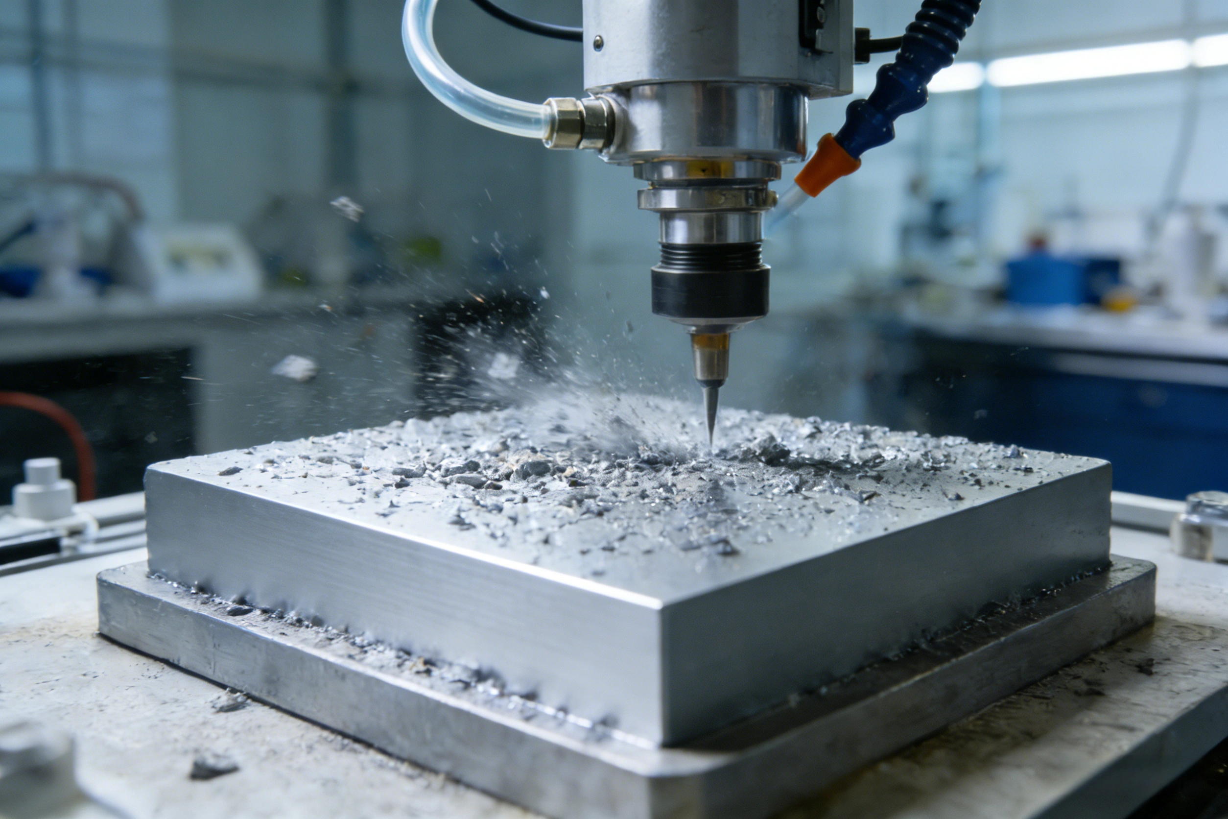
7. Shop-floor execution: blast anchor profile, inter-coat flash-off, condensation window and edge stripe coating
Body and trailer manufacture is mostly off-site steelwork or a finished-vehicle line, and coating conditions are far from those of a passenger-car paint shop. Four control points decide the outcome:
- Blast cleaning and anchor profile: heavy-duty systems are specified to ISO 8501-1:2007 (GB/T 8923.1-2011) Sa 2.5 (near-white grade: no visible oil, mill scale, rust or old coating, with only slight staining as dots and stripes among the residues), and the anchor profile is controlled to the ISO 8503 series; published engineering sources commonly give a band of about Rz 40-85 µm, with high-build and glass-flake systems taking a value at the deeper end of mid-range - but an overly deep profile leaves peak crests uncovered and initiates pitting early, and film-thickness readings must themselves be corrected for roughness (ISO 19840 wording). The published engineering limit for soluble salts is commonly not more than 50 mg/m² (as NaCl, Bresle method).
- Rust-back window and environmental red lines: the first primer coat should be applied soon after blasting and before rust-back begins (published engineering wording: within about 4 h); the substrate temperature must be more than 3 °C above the dew point, and most epoxy/polyurethane systems require relative humidity not above 80% (some TDS values relax this to 85%); in cold seasons either use a low-temperature-curing grade or heat and dehumidify, otherwise crosslinking stalls and condensation is trapped in the film, and the pull-off results will come back as a cluster of failures months later. Our detailed pretreatment notes are in Industrial coating surface preparation: blast cleaning Sa 2.5, profile and dew-point control.
- Edges and corners: cut edges and weld toes are where film thickness is weakest, so apply manual stripe coating first and spray the large areas afterwards; rounding the edge (published engineering wording: R of not less than about 2 mm) is more effective than "adding thickness". Hemmed seams, drain holes and water-pooling areas are handled to the design wording of ISO 12944-3.
- Inter-coat flash-off and recoat window: a single overthick coat of a high-build material easily gives pinholes and solvent entrapment, so build up to the target film thickness in several thinner coats; for PAE/polyurea topcoats the inter-coat and final-coat windows are locked against the gel curve - once the recoat window is exceeded the surface must be abraded; no-bake systems cure slowly in winter, so allow enough cure time before the delivery milestone.
The boundary between repair and partial repaint must also be agreed in advance: where the damage has not reached the steel substrate (a stone chip showing only coating, no rust spot) the sequence "clean - abrade - local touch-in - feathered edges" is acceptable; where the substrate is exposed or the film is worn through, blast that area locally to Sa 2.5 (or St3 where site conditions do not allow, and record it), then prime, build and topcoat, and the bond line between old and new coating must have its own system verification (separate pull-off and stone-chip sampling). The price difference between a full repaint and a local repair lies essentially in how deep the surface preparation goes, not only in the grade of coating. The test-standard family and mutual acceptance of inspection wording are covered in Automotive paint test standards: an acceptance map from GB/T to ISO.
8. Key data at a glance
- Taber wear: CS-17 / 1000 g / 1000 cycles; turntable (60±2) r/min (GB/T 1768) or 72±2 r/min (ASTM D4060); 3 parallel specimens, mass loss reported in mg/1000 cycles.
- Wheel management: new wheel outside diameter 51.6 mm, scrapped at an outside diameter of 44.4 mm; dressed once every 500 cycles; balance readability 0.1 mg.
- Stone chip (ISO 20567-1:2017): chilled cast-iron grit 3.55-5.00 mm, about 500 g per run; incidence angle 54°, nozzle distance 290±1 mm; two pressure settings of 100 kPa and 200 kPa; rating on the 0.5-5.0 class scale (class 3.0 corresponding to about 19.2% damage area).
- Stone chip (SAE J400): gravel 9.5-15.9 mm, air pressure about 483 kPa, with an optional -29 °C low-temperature setting; the -35 °C verification group rated 2-4 classes below the room-temperature group (published verification data).
- Pull-off: ISO 12944-6 verification wording gives not less than 2.5 MPa per point and no adhesive failure at the interface (unless not less than 5 MPa); engineering tenders commonly take 3-5 MPa.
- Cross-cut limits: GB/T 9286-2021 does not apply above 250 µm total thickness; ASTM D3359 Method B is limited to below 125 µm, and above that the X-cut method is used.
- Film build and salt spray: C4 high durability 240 µm (with zinc-bearing primer) / 280 µm (without zinc); NSS per GB/T 10125-2021 (35±2 °C, 50±5 g/L, pH 6.5-7.2), engineering duration bands C3 480 h / C4 720 h / C5 1440 h.
- PVC plastisol: about 95% and above solids, underbody film 1-2 mm, fusion at not less than about 140 °C for 30 min; PAE polyaspartic adhesion literature values 11.32-13.95 MPa (2.27 MPa for PVC on the same item), gel time tunable from minutes to over a hundred minutes.
- Discharge: UHMWPE liner coefficient of friction published at 0.05-0.11, recommended discharge angle about 32°, wear-resistant steel plate about 48°.
9. Acceptance sheet: these five field groups stop the arguments
| Field group | Method and wording | Elements that must be on paper |
|---|---|---|
| Surface preparation | ISO 8501-1 / GB/T 8923.1; ISO 8503 | Cleanliness grade (Sa 2.5/St3), anchor profile Rz (µm) and measurement points, salt content (mg/m²), steel temperature minus dew point at time of application (°C), RH% |
| Film thickness | ISO 2808 / ISO 19840 (roughness correction); SSPC-PA 2 wording | Design total film thickness and its allocation per layer, gauge-point layout, 90/10 judgement readings, note on correction for rough surfaces |
| Adhesion | GB/T 5210-2006 (ISO 4624); no cross-cut judgement on high build | MPa value per point + failure-mode code + failure area %, sampling location (flat surface / weld toe / edge listed separately) |
| Abrasion resistance | GB/T 1768 / ASTM D4060 (or GB/T 23988 falling sand) | Wheel type, load, cycles, measured and limit values in mg/1000 cycles, cure age, before/after ageing comparison |
| Stone chip and corrosion resistance | ISO 20567 series or SAE J400; GB/T 10125/ISO 9227 | Method number and setting, test temperature, rating class and the interface of the detachment mode, salt-spray hours + each ISO 4628 rating + scribe creep in mm |
The organising principle of the acceptance sheet: every performance item must be tied to "the four test-condition elements plus the judgement limit", and figures submitted without conditions are returned for retesting; samples from the same batch and vehicle-carried panels are retained separately, and rework responsibility is assigned field by field. Kexin New Materials supplies this class of system as B2B wholesale and OEM customisation, with the technical agreement and ex-works inspection data accompanying the goods (trade terms wording EXW/FOB), and we recommend that sample verification be run as a retest by a third party under identical conditions.
10. Frequently asked questions
Q1 The customer only wants to write "abrasion resistant, will not wear through for 5 years" - can we skip the Taber test?
You can, but the acceptance loses any arbitrable basis. "No wear-through for 5 years" is a service-life statement, and the laboratory can only supply accelerated proxy indicators. We suggest rewriting it as the triple: a wear limit (for example CS-17 / 1000 g / 1000 cycles, not more than 40 mg/1000 cycles), the total film thickness of the system with its allocation per layer, and a retention requirement for wear retested after ageing (salt spray or UV). All three figures can be produced in 2-4 weeks, which makes them far more enforceable than a "5 year" promise; field-test mileage data should be attached as supporting evidence rather than as the acceptance basis.
Q2 How do you choose between methods A, B and C of ISO 20567-1?
First confirm with the laboratory how the method number and the pressure setting are combined (published secondary accounts give two versions of the pressure that belongs to A and to B, so when you order the test state the setting parameters explicitly instead of only the method letter), then choose the setting by location: routine screening of a full e-coat / surfacer / clearcoat stack goes to the multi-impact setting (Part 1, 54° gravel stream); checking the extreme adhesion case of "one stone hitting once" goes to Part 2 with the guided projectile, measuring the detachment width; scenarios that need the energy of a real flying gravel piece go to Part 3. For the acceptance line we recommend two temperatures: one setting at room temperature and one below zero - for a commercial vehicle, omitting the low-temperature setting amounts to not testing.
Q3 Can pencil hardness 3H be used to accept a truck body paint for abrasion resistance?
No. Pencil hardness measures resistance to scratch indentation and belongs to the passenger-car clearcoat scratch-resistance context; body failure is abrasive particles micro-cutting repeatedly under normal load combined with dropped-cargo impact. A formulation that is hard but not tough may show a small mass loss on Taber yet detach in sheets at the stone-chip setting. The sensible wording is the triple of Taber mass loss (mg/1000 cycles) + ISO 20567 or SAE J400 rating + pull-off MPa; hardness should at most serve as an in-process reference indicator.
Q4 PVC underbody material or polyurea - what should a trailer plant choose?
It depends on whether there is an oven and on the rework mode. With a paint-line oven and stable volumes: PVC plastisol is a mature process, gives a thick film in one coat, and a 1-2 mm elastic layer at controllable cost, but fusion needs about 140 °C for 30 min, so field repair and conversion work cannot use it. For conversion shops, repair lines and export loose parts: the no-bake route comes first, and both moisture-cure polyurethane and solvent-free PAE polyaspartic can be applied at ambient temperature; the published adhesion and post-impact retention figures are markedly better than PVC, at the price of greater sensitivity to substrate cleanliness, mix ratio and application window - gel times in the minute range mean the recoat window must first be locked by a shop-floor trial (see our dedicated polyaspartic article for details).
Q5 Cross-cut class 0 and pull-off 8 MPa contradict each other - which do you believe?
At high build, believe the pull-off. Above 250 µm total film thickness the cross-cut test is outside the scope of GB/T 9286-2021, and the mismatch between cutter spacing and film thickness produces a false class 0 because the cuts did not go through; the pull-off gives an MPa value plus an interface failure code and points directly at the weak plane (substrate interface, intercoat, or cohesive). If the two results of the same system conflict, re-check with the X-cut method of GB/T 31586.2 and record the failure mode and sampling position (flat surface / weld toe / edge) in the report.
Q6 Winter schedule pressure: humidity 85% and steel temperature equal to the dew point - can we keep spraying?
No. Condensation seals water at the interface; the pull-off may pass at the time, then fail in sheets at edges and weld seams three months later. The red lines are steel temperature at least 3 °C above the dew point and, for most epoxy/polyurethane systems, RH not above 80%; when the conditions are exceeded you either heat and dehumidify, or switch to a grade explicitly permitted to cure at high humidity (the TDS must state it and the written evidence must be kept), or you stop spraying. The cost of a compressed schedule has never been two hours of lost spraying - it is a full vehicle strip-back.
Q7 On the body slide-plate zone: a coating or a UHMWPE liner?
Do the total accounting by material handled. For high-wear lines with ore fines and spoil: UHMWPE/HDPE liners are sacrificial items, with a published coefficient of friction of 0.05-0.11 and a discharge angle that can fall about 10-16° below the steel-plate solution, and the coating retreats to protecting the steel under the liner and rust-proofing the joints; for grain and fertiliser: the abrasives are soft and corrosion dominates, so an abrasion-resistant topcoat with sensible film build is enough, while a liner would introduce cleaning dead zones; for mixed cargo: high-build elastic system on the steel plate plus local liner strips in the critical bands. The acceptance differences must also be stated: for liners you inspect bolt holes and joints, for coatings you inspect the five field groups of Table 6.
11. References and wording notes
- ISO 20567-1:2017, Paints and varnishes - Determination of resistance to stone chipping - Part 1: Multi-impact test (issued 2017, replacing the 2005 edition; citing ISO 11124-2:1993, ISO 1514:2016, ISO 21227-2:2006, ISO 2808, ISO 3270, among others); ISO 20567-2:2023 (single impact, guided projectile); ISO 20567-3:2012 (single impact, free-flight projectile). The secondary accounts of the pressure-to-shot-count combinations for methods A/B/C differ between versions, and this is flagged as a wording caveat in the text.
- GB/T 1768-2006, Paints and varnishes - Determination of abrasion resistance - Rotary rubber wheel method (identical to ISO 7784-2:1997; the current edition was revised and re-issued in 2020 and the current text governs); ASTM D4060, Standard Test Method for Abrasion Resistance of Organic Coatings by the Taber Abraser (current edition re-approved in 2025; wear index, S-11 dressing, 72±2/60±2 r/min and precision figures are taken from its published text); ISO 7784-2:2023. Falling-sand method: GB/T 23988-2009, ASTM D968.
- GB/T 5210-2006, Paints and varnishes - Pull-off test for adhesion (IDT ISO 4624:2002); GB/T 9286-2021, Paints and varnishes - Cross-cut test (IDT ISO 2409:2020, not applicable above 250 µm total thickness); GB/T 31586.1-2015 / GB/T 31586.2-2015 (pull-off and cross-cut/X-cut acceptance criteria, corresponding to the ISO 16276 series); ASTM D3359 (Method B limited to below 125 µm).
- ISO 12944-1:2018 (durability ranges L/M/H/VH and the Ri3 maintenance trigger), ISO 12944-2:2017 (first-year carbon-steel corrosion of 200-400 / 400-650 g/(m²·a) for C3/C4), ISO 12944-5:2018 with GB/T 30790.5-2014 (prescriptive system and film-build examples), ISO 12944-6:2018 (pull-off 2.5 MPa / 5 MPa, scribe creep 1 mm / 3 mm, cyclic ageing pattern); equivalent salt-spray methods GB/T 10125-2021 (MOD ISO 9227:2017) and GB/T 1771-2007 (IDT ISO 7253:1996); ratings by the ISO 4628 series and GB/T 6461.
- Surface preparation: ISO 8501-1:2007 / GB/T 8923.1-2011 (definitions of Sa 2.5 and St3), ISO 8503 series (anchor profile), ISO 19840 (roughness correction), Bresle salt wording (engineering value not more than 50 mg/m²).
- SAE J400 / ASTM D3170 gravel impact and the list of OEM specifications (PV 1213, GMW 14668, FLTM BI 157, 463PB, etc.): taken from published compatibility material of testing bodies and equipment makers; the original parameter text of the corporate standards has not been cited item by item.
- Wang Nan et al., Comprehensive performance study of polyaspartic polyurea for chassis protection of new-energy vehicles, Tu Liao Gong Ye / Paint Industry, 2023, Vol. 53, Issue 1, pp. 51-58; Xia Yuan et al., Research status of polyaspartic polyurea coatings, Tu Ceng Yu Fanghu / Coating and Protection, 2025, Vol. 46, Issue 5, pp. 36-38; Yang Xueyan and Zhang Kejia, Application of PVC and polyurethane coatings on passenger cars, Qiche Gongyi yu Cailiao / Automobile Technology and Materials, 2008, Issue 9 (PVC fusion at 140 °C and above for 30 min, the polyurethane sill transition conclusion, and the PAE adhesion and cure comparison figures are all quoted at second hand).
- Body liner and discharge parameters (UHMWPE coefficient of friction 0.05-0.11, recommended discharge angles 32°/35°/48°, etc.) come from industry-published selection material and product technical pages of 2025-2026 and are engineering reference wording.
- CAAM group standard drafting note for the Test method for gravel impact of automotive wheel coatings (project 2023-77): evidence that no equivalent converted national standard existed in China previously.
Wording note: the test parameters in this article come from published standard information, from public material of third-party testing laboratories and equipment makers, and from secondary quotations of journal literature, and are intended for engineering selection and acceptance communication. The pairing of methods A/B/C of ISO 20567-1 with the pressure settings differs between secondary sources; before formal commissioning or arbitration, refer to the current standard text itself and the laboratory's method confirmation sheet. Salt-spray hours and ISO 12944 durability years are not directly convertible; film-thickness ranges, cure windows and friction coefficients are indicative ranges from published sources and vary with product formulation, batch and application conditions.
Last updated: 2026-11-03 | Byline: Kexin New Materials (Guangdong) Co., Ltd. (B2B technical literature, trade terms wording EXW/FOB)