
Mobile elevating work platforms (MEWPs) and suspended access platforms (gondolas) are lifting or travelling equipment with a manned, guarded platform; the load-bearing structure typically consists of boom, turntable, chassis, suspension rig and platform frame. Anticorrosion coating of this steelwork is bound by three kinds of surface at once - protective surfaces, mating surfaces and inspection surfaces - which is why "where to cap the film thickness and where to leave the steel bare" usually takes precedence over the choice of coating system itself. Working from publicly available readings of the ISO 12944 series, EN ISO 1461 and GB/T 13912, ISO 19840, EN 280 and GB/T 19155, this article sets out environmental classification, dry film thickness, surface preparation, the demarcation of paint-free zones, galvanising and duplex routes, and acceptance records as criteria that OEMs, rental-fleet maintenance teams and coating subcontractors can execute directly in technical agreements and process documents.
Consider a real repair case. A telescopic-boom MEWP had served four years at a coastal plant when three different failure modes appeared on the same machine: the coating in the slide-pad contact zone on the underside of the telescoping boom had worn through, leaving banded rust trails; the pin-and-bore joint between turntable and boom had been over-coated during the previous repair with two heavy epoxy coats, so the pin could no longer be pressed in and the site team ended up reaming the bore; and although the outer barrel of the outrigger cylinder was still sound, blistering and peeling had appeared in the annular band where the rod-port seal meets the sliding surface. The common cause of all three was not "bad paint" - it was carrying the building-steelwork habit of "the thicker the film, the safer" straight onto a machine that has mating surfaces and moving surfaces.
I. First Define the Object: This Is Not Ordinary Building Steelwork
The coating objective for building and bridge steelwork is fairly single-minded: suppress rust within a defined corrosivity class and design life. MEWPs and gondolas add a further constraint - they are moving structures that carry people, so the presence or the thickness of a coating directly changes mating dimensions, friction behaviour, conductivity and insulation, and whether an inspector can actually see a defect.
1. Three surface types conflict with one another on the same machine
- Protective surfaces: outer boom sides, turntable flats, chassis top covers, platform frames and guard-rail posts. For these, the system and the film thickness follow the ISO 12944 series, with exactly the same logic as ordinary steelwork.
- Mating surfaces: pins and bores, hinge bushings, telescopic-boom slide-pad contact faces, outrigger-cylinder guide sleeves, the faying surfaces of friction-type high-strength bolted joints, threaded holes and circlip grooves. Here a coating is an "added dimension": it eats into the tolerance band, lowers the slip coefficient of friction-type joints, and changes the wear mode of the friction pair.
- Inspection surfaces: wire ropes, chains, welds, the exposed pin sections at hinges, speed-limiter friction-wheel contact faces, and viewing holes into hollow members. These must stay bare-metal or lightly covered, because coating hides broken wires, cracks and deformation and directly undermines scrap decisions made on a periodic basis.
The practical order of work should be: first mark the paint-free boundaries of mating and inspection surfaces on the drawings and in the technical agreement, then set system and film thickness for every other surface. Reverse the order and you get the vicious circle in which "the thicker the spray, the better acceptance looks - and the harder every assembly step becomes".
2. Maintenance windows and rework costs magnify small defects
This kind of equipment typically runs continuously on rental sites or work-dense jobs, and the coating window that can be freed up usually shares the slot with the annual inspection, hydraulic-component replacement and NDT of structural members. Localised touch-up is done on site, and the area that can realistically be blast cleaned to Sa 2½ in the field is usually limited; most repairs only reach St 3 with hand and power tooling. In other words, the system chosen at first application decides whether, three to five years later, local repairs can stay inside the same system. If the original build used a product with a narrow intercoat recoat window and a sensitivity to rust bleed, rework easily escalates into "strip the whole panel and start again".
3. The standards leave a gap: machine standards govern structural safety; coating requirements belong in the technical agreement
On the suspended access platform (gondola) side, the current Chinese national standard is GB/T 19155-2017 for suspended access equipment (gondolas) used for work at height (issued 2017-07-12, implemented 2018-08-01, replacing GB/T 19155-2003; China standard classification number J80, ICS 53.020.99, administered by the China Machinery Industry Federation). Its scope covers terms and definitions, types and main parameters, general technical requirements, structure, stability and mechanical design calculations, the suspended platform, hoisting mechanisms, suspension equipment, electrical and control systems, test methods, inspection rules, marking and accompanying documentation - but the publicly available table of contents sets no coating dry film thickness and no anticorrosion system. On the mobile elevating work platform side, the EU harmonised standard is the EN 280 series (the new edition being EN 280-1:2022, covering design calculations, stability criteria, construction, safety, examinations and tests). Common criteria relayed through public channels by third-party certification bodies include: static proof load of 1.5 times the rated load on primary structural members, dynamic test at 1.25 times, guard-rail height not less than 1,100 mm, mid-rail spacing not more than 550 mm, toe-board height not less than 150 mm, an alarm or cut-out action at a wind speed of 12.5 m/s, hydraulic lines and fittings proof-tested at twice the working pressure, and electrical systems per EN 60204-1 with insulation resistance not lower than 1 MΩ. Different certification bodies' public accounts disagree on the exact pairing of the static and dynamic load factors, so the text of the current standard and the design documents take precedence.
The conclusion is practical: anticorrosion requirements do not vanish because the machine standard is silent; they have to reach the drawings through the purchase technical agreement, the enterprise standard and the coating process document. Whoever writes the paint-free list and the film-thickness caps into the agreement holds the initiative in assembly and acceptance.
II. Environmental Classification: Do Not Discuss Systems Before Fixing the Corrosivity Class
ISO 12944-2:2017 defines atmospheric corrosivity classes from the first-year mass loss or thickness loss of mild steel and zinc; the 2017 edition merged the former C5-I and C5-M into a single C5 and added the extreme offshore class CX. The table below is a comparison chart compiled from public sources.
| Class | Corrosivity | Thickness loss of mild steel µm/a | Thickness loss of zinc µm/a | First-year mass loss of mild steel g/m² | Typical environment examples |
|---|---|---|---|---|---|
| C1 | Very low | ≤1.3 | ≤0.1 | ≤10 | Heated interiors with clean air |
| C2 | Low | 1.3–25 | 0.1–0.7 | 10–200 | Unheated interiors, rural atmospheres |
| C3 | Medium | 25–50 | 0.7–2.1 | 200–400 | Urban and general industrial atmospheres, low-salinity coasts |
| C4 | High | 50–80 | 2.1–4.2 | 400–650 | Medium-salinity coasts, industrial areas, chemical plants |
| C5 | Very high | 80–200 | 4.2–8.4 | 650–1500 | High-humidity, heavily polluted industrial areas; high-salinity coasts (former C5-I and C5-M merged) |
| CX | Extreme | >200 | >8.4 | 1,500–5,500 | Offshore installations, atmospheric zone of marine structures (systems per ISO 12944-9) |
1. One machine commonly sits in two classes at the same time
A whole machine is not designed to a single class. The outer boom faces sun and rain wash - close to ordinary atmospheric exposure. The chassis underside, weight-mounting faces and inner wheel frames accumulate mud and de-icing salt, so their micro-environment is more corrosive than the nominal class. Gondola suspension-rig supports and rooftop counterframes stand unsheltered year-round, while platform frames park in indoor turnaround storage. Publicly available ISO 12944 implementation guidance also notes that local micro-environments such as bridge shadow faces or swimming-pool roofs can corrode two to three classes faster than the main structure and need separate assessment. So write the agreement as two lists - zone and class - rather than one contract line reading "C4 system".
| Location | Exposure characteristics | Suggested class | Additional constraints |
|---|---|---|---|
| Boom outer faces, turntable, exposed platform-frame parts | Atmospheric exposure, UV, wet-dry cycling | C3–C4 | Topcoat must resist chalking; epoxy intermediate coats must be overcoated |
| Chassis lower flanges, inner wheel frames, weight mounting faces | Mud, de-icing salt, mechanical knocks | C4–C5 | Elastic thick-film or bituminous underbody sealing, also against stone chip |
| Machines used within 5 km of the coast, at docks or offshore wind sites | Heavy sea-salt aerosol deposition | C5 | Extra edge pre-coating and high-voltage holiday (spark) testing |
| Gondola suspension rigs, rooftop frames, exposed wire-rope sections | Unsheltered; salt spray alternating with condensation | C4–C5 | Ropes and friction wheels stay paint-free (see Section V) |
| Scissor lifts parked long-term in indoor turnaround storage | Stable dry temperature, occasional condensation | C2–C3 | Focus on chip repair rather than full re-spraying |
2. Mind the vintage gap in the Chinese adopted editions
In China the ISO 12944 series corresponds to the GB/T 30790 series (for example GB/T 30790.2-2014 for environmental classification, GB/T 30790.5 for protective coating systems, GB/T 30790.6 for laboratory performance test methods). The adopted editions are based on the 1998 ISO version, while the international series completed its revision in 2017-2018: C5-I and C5-M merged, CX added, durability tiers adjusted and the recommended nominal dry film thicknesses generally lowered. When a project cites GB/T 30790, also state in the agreement which ISO edition is intended (e.g. ISO 12944-5:2018), so that the two rulers do not fight.
III. Durability Tiers and Nominal Dry Film Thickness: Life Is the Primary Constraint
ISO 12944-1:2017 expands durability from three tiers to four: low durability ≤7 years, medium durability 7–15 years, high durability 15–25 years, very high durability >25 years; and it tightens the criterion for first maintenance to "about 10% of the surface reaching the defined rustiness rating", not rust across the whole area. The durability tier and the corrosivity class together determine the nominal dry film thickness (NDFT) of the recommended system. The table below is compiled from public sources; several independent references agree closely, but all are restatements - for contract use, verify against the current standard text.
| Corrosivity class | Primer type | Low durability ≤7 years | Medium durability 7–15 years | High durability 15–25 years | Very high durability >25 years |
|---|---|---|---|---|---|
| C3 | Other primer | 120 | 160 | 200 | 240 |
| C3 | Zinc-rich primer | — | — | 160 | 200 |
| C4 | Other primer | 160 | 200 | 240 | 280 |
| C4 | Zinc-rich primer | 120 | 160 | 200 | 240 |
| C5 | Other primer | 200 | 240 | 280 | 320 |
| C5 | Zinc-rich primer | 160 | 200 | 240 | 280 |
| CX | — | Moved to the dedicated offshore provisions of ISO 12944-9:2018 | |||
Two cautions. First, the 2017-2018 revision lowered the recommended NDFT by roughly 40–60 µm at equal class and life: thinner films, but a stricter system and stricter surface preparation - you cannot copy the old thicknesses while relaxing the pretreatment. Second, NDFT is the target for protective surfaces (the exposed faces in Table 1), not an allowance for mating surfaces - the film-thickness cap on mating surfaces must be specified separately, which is the subject of Section V. For the logic linking film thickness to service life, see our article General anticorrosion systems for steel structures: the primer-intermediate-topcoat layers and the film-thickness logic; bridges and heavy-duty steelwork are covered in Coating specification for bridge steelwork anticorrosion.
IV. Surface Preparation: Cleanliness, Anchor Profile, Dust and Salts - Four Gates
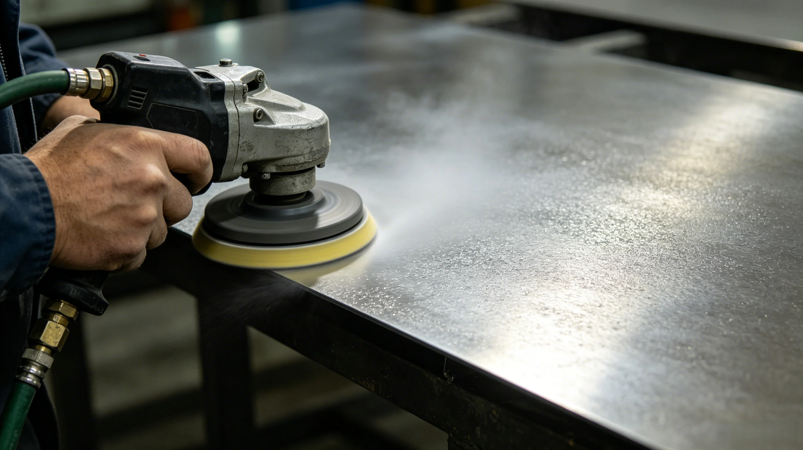
Most failures of protective surfaces do not start inside the coating but at the interface between coating and substrate. For MEWPs and gondolas there is an extra layer: on-site or repair bays rarely reach high blast-cleaning grades over the full area, so state up front where Sa 2½ is mandatory and where St 3 is acceptable.
| Item | Common criterion | Method or standard | Notes |
|---|---|---|---|
| Cleanliness grade | Protective surfaces Sa 2½ (residual discolouration covering ≤5% of the area); CX or thermal-spray surfaces Sa 3; localised repair St 3 | ISO 8501-1 / GB/T 8923.1-2011 | Welds, inside corners and pit fields are graded as the worse zone |
| Anchor profile (surface profile) depth | Heavy-duty work commonly Rz 40–75 µm; shipbuilding and offshore systems 30–75 µm | ISO 8503 series / GB/T 13288 | Too deep leaves thin film on the peaks; too shallow undercuts adhesion |
| Dust grade | Heavy-duty work requires grade 1; no particles of class 3 or coarser may remain | ISO 8502-3 / GB/T 18570.3 | Pressure-sensitive tape replica comparison |
| Soluble salts | ≤50 mg/m² as NaCl is the common cap; high-performance systems take ≤20–30 mg/m² | ISO 8502-9 field method / ISO 8502-6 laboratory method | ISO/TR 15235 recommends 30 mg/m² in public readings; mandatory testing in coastal and de-icing-salt service |
| Ambient conditions | Substrate temperature at least 3 ℃ above dew point; relative humidity ≤85% | General clause of application specifications | Record every 2 h; re-measure after abrupt changes |
| Time limit before coating | Primer within 4 h of Sa 2½; shortened to 2 h on coasts or in high humidity | Common wording in enterprise process documents | Any rust bleed must be reworked |
| Edge treatment | Free edges broken to a radius of not less than 2 mm or worked by equivalent repeated grinding | Public requirement of the IMO ballast-tank coating performance standard | Film on sharp edges falls short by a multiple |
1. Rust bleed and desalting: the order of operations
Between blast cleaning and the first primer coat, bare steel in a humid atmosphere can flash-rust back within two to three weeks; acid-cleaned members are typically stored no longer than one month, and ground faces should be coated within 24 h. Where flash rusting stays below 5% of the area, key it with fine abrasive, wipe down with fresh water, let it dry to touch and coat; above 5%, re-blast. If fresh-water rinsing is used to remove salts, it must be paired with high-pressure washing and thorough drying, otherwise water left in capillary gaps becomes a new blistering source. Our companion article on rust-bearing substrates: Surface preparation of rusty steel and the boundaries of convertible coatings.
2. How much weight preparation carries in coating life
The rule of thumb widely quoted in public sources: of a coating system's in-service performance, surface preparation contributes about 60%, the paint itself about 30%, and application factors about 10%; each step the preparation grade drops, long-term maintenance frequency rises visibly. The ratio comes from second-hand retelling and cannot be cited as a standard clause, but for persuading an owner that the money should go to preparation before topcoat branding it is usually sufficient.
V. Booms, Hinges and Slide Faces: Criteria for Paint-Free Zones and Thickness Caps
This chapter is where the article parts company with generic steel-coating guides. Whether a face should be coated, and how thick, is decided by three criteria: dimensional (does the coating eat into a fit tolerance?), mechanical (does it change friction or the load path?) and functional (does it compromise conductivity, insulation, movement or inspection?).
| Location | Governing criterion | Suggested disposition | Quantitative basis |
|---|---|---|---|
| Pins and hinge bores | Dimensional | No coating inside the bore or on the pin outside diameter; after assembly, seal only the exposed end faces | For a Ø30–40 mm bore, tolerance class H7 gives a band of only +0.025 mm, while a single heavy-duty coat typically runs 60–120 µm of dry film - two to five times the band |
| Faying surfaces of friction-type high-strength bolted joints | Mechanical | Follow the design documents; the slip coefficient of friction must be re-measured before assembly | JGJ 82 table values via public restatement: blast cleaning (grit or shot) 0.45 / 0.55; blast cleaning followed by an inorganic zinc-rich coat falls to 0.35 / 0.40; galvanised surfaces 0.17 |
| Telescopic-boom slide-pad contact faces | Mechanical + wear | No thick-film coating on sliding faces; use wear pads or a wear-resistant powder coating instead | Once worn through, the coating forms a local galvanic couple with the substrate and the worn band propagates in stripes |
| Cylinder rod-guide ports and seal contact faces | Functional | The annular band at the port stays paint-free; mask with plugs before spraying | Coating debris embedded in the seal lip scores the plated piston rod |
| Threaded holes, circlip grooves, threaded parts | Dimensional | Leave uncoated, or reserve a coating-compensation tolerance in advance | Compensation is commonly quoted in the 0.2–0.4 mm range (public wording) and must be agreed with the fastener supplier |
| Wire ropes, chains, speed-limiter friction wheels | Functional (inspectability) | Film-forming paint prohibited; use penetrating rope lubricant per the manufacturer's specification | Broken wires and deformation must remain visible; paint hides defects and changes the rope diameter |
| Electrical bonding faces and earth bolts | Functional (conductivity) | Keep bonding faces bare, or break the film locally after coating | On insulated models, conductive coatings also change the boom's insulation state; the OEM's technical documents govern |
1. Pin bores: a single coat can swallow the whole tolerance band
Hinged structures commonly use clearance fits such as H7/g6. For Ø30–40 mm, tolerance class H7 gives the bore band +0.025 mm / 0 - a radial margin of only 25 µm. A single heavy-duty coat, by contrast, typically lands at 60–120 µm dry film (see the C4 high and very-high durability rows of Table 3, where a total NDFT of 200–240 µm is usually built in two or three coats). "Helpfully" adding two coats into the bore during a repair can accumulate well over a hundred micrometres; the pin then presses in far too tight, and the site reams the bore or grinds the shaft - a step that actually breaks the sealed boundary of the original system and leaves the corrosion start exactly on the bare metal exposed by reaming.
The correct drawing note marks the paint-free circle directly: bore and pin coated up to the edge only; after assembly, locally seal the exposed end faces (which faces are coatable and which are not, as drawn in the technical agreement); and write "recoating of pin bores requires design confirmation" into the repair procedure. The same logic covers paint-free zones on chassis and frame parts - our article Paint-free zones on frames and chassis parts: bonding continuity, mating faces and e-coat thickness boundaries develops it further from the vehicle electrics and assembly side.
2. Faying surfaces: paint lowers the slip coefficient
Friction-type high-strength bolted joints transmit force through plate-to-plate friction, and the slip coefficient of friction µ is tied directly to the faying-surface process. Public restatements of the JGJ 82 table give the following pairing: blast-cleaned (grit or shot) surfaces of grade-3 steel and 16Mn steel at 0.45 / 0.55; after blast cleaning plus an inorganic zinc-rich coating, down to 0.35 / 0.40; blast cleaning followed by controlled atmospheric rusting still 0.45 / 0.55; wire-brushed loose rust or untreated clean mill-scaled surfaces 0.30 / 0.35; and galvanised surfaces of cold-formed thin-wall members at only 0.17. Some public sources quote a higher 0.45–0.55 for inorganic zinc-rich coatings on blasted surfaces, conditioned on a 50–75 µm dry film, a zinc powder content of not less than 80% and full curing for at least 24 h; the two sets of readings disagree. The engineering conclusion is single: µ must be established by testing on specimens of the same material, same process and same batch - never taken on faith from a table. The publicly reported sampling wording is one inspection lot per 2,000 t or per surface-treatment process, with 3 specimen groups per lot; acceptance requires the specimen mean to be at or above the design value and no single specimen below 85% of the design value.
For a MEWP this means: if the load-bearing connections between boom and turntable are designed as friction-type, the coating sequence must be planned around faying-surface protection and µ re-verification. During works, marking or oil contamination of faying surfaces is strictly prohibited; at installation the faying surfaces must stay dry and no work in the rain. Pretension and torque are controlled, per the public wording, to a deviation of ±10%, with the torque coefficient of the assembly bolting averaging 0.110–0.150 and a standard deviation not exceeding 0.010. Related in-depth article: Can high-strength bolt faying surfaces be painted? Slip-coefficient values and re-verification under coatings.
3. Telescopic slide faces and wear components
Telescoping booms slide on polymer pads or wear shoes, and the running clearance exists precisely to absorb wear. Organic coatings are not the wear solution here: under cyclic contact the coat wears through first, the worn band sets up a potential difference against the surrounding intact coating, striped rust propagates along the band, and wear debris migrates into the fit. Where surface wear resistance must be raised, take the wear-resistant powder coating or surface-engineering route instead of thickening the anticorrosion film. See Wear-resistant powder coatings: hard fillers, wear mechanisms and duty selection, and the discussion of trading thick film, fast cure and weatherability on construction machinery: Construction-machinery coatings - balancing thick film, fast dry and weatherability.
4. Threads, circlip grooves and sealing faces
Coating inside internal threads reduces the effective engagement diameter and, in the worst case, stops a nut running home or produces "phantom torque". On external threaded parts, the openly documented industry practice is to reserve a coating-compensation tolerance before plating or painting, commonly in the 0.2–0.4 mm range. On aerial work platforms and gondolas, once fine-pitch holes, adjusting screws and lead screws pick up film, the functional judgement of levelling and safety limit devices is affected directly. Recommendation: prefer pre-coated fasteners as finished parts (proved by the supplier's process) rather than touching up threads on site; if field touch-up happens at all, restrict it to exposed ends and record which thread lengths do not carry load.
VI. Hot-Dip Galvanising and Duplex Systems: the Mainstream Route for Chassis and Structures
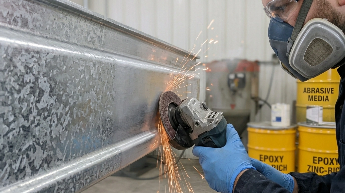
For complex, volume-produced welded assemblies - chassis parts, counterweight frames, gondola suspension rigs - hot-dip galvanising covers edges and hollow interiors more reliably than field painting. EN ISO 1461 (mirrored in China by GB/T 13912-2020) controls the deposit with a dual criterion of local minimum plus average thickness; that is what distinguishes it from standards that give averages only.
| Nominal steel thickness | Minimum local thickness µm | Minimum average thickness µm | Reference coating mass g/m² |
|---|---|---|---|
| >6 mm | 70 | 85 | 505 / 610 |
| >3 mm to 6 mm | 55 | 70 | 395 / 505 |
| 1.5 mm to 3 mm | 45 | 55 | 325 / 395 |
| <1.5 mm | 35 | 45 | 250 / 325 |
| Castings ≥6 mm / <6 mm | 70 / 60 | 80 / 70 | 505 / 575 and 395 / 505 |
| Centrifuged articles (threaded parts etc.) >6 mm / 3–6 mm / <3 mm | 45 / 35 / 25 | 55 / 45 / 35 | Zinc conversion: 1 µm ≈ 7.14 g/m² |
Public conversion readings of EN ISO 9224 give zinc atmospheric thickness loss from 0.1–0.7 µm/a in C1 to 4.2–8.4 µm/a in C5. On that basis an 85 µm average zinc layer in C4 (2.1–4.2 µm/a) lasts a bare-coating consumption limit in the region of 20–40 years. Actual life, however, depends heavily on micro-environment, dirt-trapped moisture and bare steel at edges, and public sources commonly state the duplex (galvanised plus painted) system life gain as 1.5–2.5 times that of a single system of equal thickness. That multiplier is an industry retelling, not a clause of any single standard, and citations should say so.
1. Silicon, phosphorus and the over-thick grey coating
Steel chemistry drives coating growth. The publicly quoted criterion: silicon between 0.03–0.12% or above 0.25%, with phosphorus above 0.02%, puts the steel into the "reactive steel" (Sandelin) range, where the coating can run to 200–300 µm, turn grey and dull, and go brittle at edges. EN ISO 14713-2 classifies by Si + 2.5 P: below 0.04% is class A (normal bright coating), 0.14–0.25% is class C (thicker but usable), and in between lies the unpredictable class B. The procurement consequence: for hot-dip galvanised parts, thickness cannot live only on the drawing - Si and P must also appear in the material certificates. An over-thick deposit changes the interface state for subsequent coating and the fit dimensions, so boom hinge points and similar areas may need rework or pre-reserved machining allowance. Hot-dip galvanising typically adds 3–6% in mass and, in extreme cases, up to 15%, which feeds into the whole-machine counterweight and stability-moment calculations.
2. Priming directly onto galvanised steel: the adhesion prerequisites
A fresh galvanised surface cannot take a plain epoxy directly. Three publicly documented options: sweep blasting (a light Sa 1 pass) to raise roughness, phosphate or chromate conversion treatment, or a vinyl butyral wash primer (etch primer) system; the substrate condition before coating galvanised steel should also be graded and recorded per ISO 8501-3. If blasting follows galvanising, remember the alloy layers at the zinc/iron interface are brittle and excessive pressure damages them. For long-life structures, thermal-sprayed zinc or aluminium followed by a sealer is an equivalent route; the mechanism and system pairing are covered in Thermally sprayed zinc-aluminium metallic coatings: cathodic protection mechanism and ISO system pairing.
VII. Welds, Edges, Hollow Sections and Water-Holding Details
On sharp edges, surface tension pulls heavy-body material away; measured edge film thickness often falls to half the flat value or worse. Edge pre-coating (stripe coat / pre-coat of edges) is therefore part of the system, not an optional extra. Suggested wording: on every free edge, cut edge, weld, bolt head and hollow-section end, brush-precoat first at roughly 20% above the nominal system thickness, then spray the flats.
Hollow sections (box booms, gondola platform frames, square-tube suspension rigs) carry three risks to handle with priority: water that collects inside where it can be neither cleaned nor inspected; flux residue and mill scale left after welding; and capillary gaps at poorly sealed ends, which draw in salt-bearing water by capillary action and creep along internal walls where nothing can be seen or probed. Public implementation guidance gives two criteria: closed sections must be provided with drainage and inspection holes, positioned for the actual installed attitude; and sealing of lap faces and gaps must use an elastic sealant that will not dissolve metallic layers. The logic parallels indoor high-humidity condensation duty - see Steel protection in indoor swimming-pool halls: systems for chlorinated, humid, condensing environments and the ammonia-corrosion example of livestock buildings: Livestock-building steelwork: ammonia-rich humid environments and coating systems.
On coastal and dockside machines the edge problem bites harder. Our articles cover the C5 and former C5-M marine atmospheric system logic and the combined effect of UV and biofouling: Marine engineering C5-M systems: combined protection against salt spray, UV and biofouling, and the choice of salt-spray-resistant topcoats for port machinery: Heavy-duty nano topcoat with salt-spray resistance for port machinery.
VIII. Acceptance: Four Records - Keep All Four
Write delivery acceptance as four records: the pretreatment log, the film-thickness log, the holiday-detection and adhesion log, and the paint-free-zone and repair log. The first three rest on general standards; the fourth is specific to this equipment class and the one most often skipped in practice.

1. Film thickness: the 80/20 rule of ISO 19840
ISO 19840:2012 applies to protective systems with a nominal dry film thickness of not less than 40 µm. Acceptance must satisfy four conditions at once: the mean reading of a measurement area is at or above the NDFT; no single reading falls below 80% of the NDFT; readings lying between 80% and 100% of the NDFT make up less than 20% of the total; and no reading exceeds the maximum given by the specification. Measurement points scale with area: 5 points up to 1 m², 10 for 1–3 m², 15 for 3–10 m², 20 for 10–30 m², 30 for 30–100 m², then 10 more points per additional 100 m². Blast-profiled surfaces make instruments read high, so correct per the ISO 8503-1 roughness bands - fine 10 µm, medium 25 µm, coarse 40 µm; when unknown and without a bare reference plate, take 25 µm. If a single point is out of tolerance, it may be re-measured within 10 mm and, if compliant, replaces the original value. Note this differs from the 90/10 rule of the IMO ballast-tank performance standard (90% of readings at or above the NDFT and the remaining 10% at or above 0.9 times the NDFT, with an NDFT target of 320 µm); on maritime or offshore scope, first check which ruler the contract uses.
Our article Surface preparation Sa 2.5 and blast cleaning grades expands on gauges and reading corrections for film-thickness measurement.
2. Holiday (pinhole) detection and adhesion
Holiday and pinhole detection depends on coating thickness: thin builds can use the low-voltage wet-sponge method (public sources commonly quote around 90 V); thick systems switch to high-voltage spark detection, with the test voltage set from the instrument maker's formula and the coating thickness. Adhesion acceptance uses the pull-off test, methods ISO 4624 / GB/T 5210 (or ASTM D4541). Common heavy-duty specifications set not less than 5 MPa; public wording for the IMO ballast-tank system gives above 3.5 MPa for epoxy-based systems and above 5.0 MPa for alternatives, distinguishing the proportions of interfacial and cohesive failure. Judgement must combine the number with the failure mode - reading the number alone misleads; details in Adhesion acceptance for anticorrosion coatings: pull-off numerical criteria and failure modes.
3. The paint-free and repair record - the one always cut
Suggested contents: the numbered map of paint-free faces; the pre-assembly verification result (does the pin slide in freely? are the faying-surface protections intact?); each repair location with the cleaning grade actually achieved; the repair overlap width (a common requirement is not less than 50 mm) and feather-edge width (not less than 30 mm); and the post-repair re-measured film thickness and adhesion. If this record survives into factory acceptance and annual inspection files, later accident attribution and quality claims carry far fewer technical disputes.
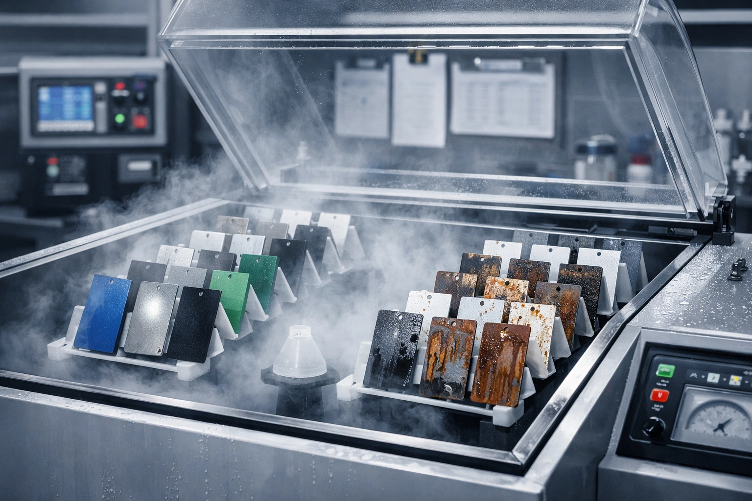
IX. Laboratory Qualification: Do Not Convert Salt-Spray Hours into Service Years
Salt-spray testing is an accelerated comparative tool; there is no stable linear conversion between spray hours and years of atmospheric exposure. Neutral salt spray per ISO 9227 runs at 35 ℃ with 5% NaCl; ISO 12944-6 and -9 judge by creep width from a deliberate scribe, and the commonly restated public requirement is creep of not more than 2.0 mm per side from the scribe for C3 and C4, and not more than 2.5 mm for C5 and CX.
| Qualification item | C3 | C4 | C5 | CX |
|---|---|---|---|---|
| Neutral salt spray (NSS) duration h | 240 | 480 | 720 | 720–1,440 |
| Condensation test duration h | 240 | 480 | 720 | 720–1,440 |
| Cyclic ageing (ISO 12944-9) | Not required | Optional | 2,520 (35 cycles) | 4,200 (58 cycles) |
| Scribe creep criterion mm | ≤2.0 | ≤2.0 | ≤2.5 | ≤2.5 |
| Typical test panel size mm | 150 × 100 × 3 or 150 × 75 × 3 (IMO simulated-tank panels 200 × 400 × 3) | |||
Public restatements give 72 h per cycle for cyclic ageing: 24 h salt spray, 24 h condensation, 12 h low temperature at -20 ℃, and 12 h UV. This kind of multi-factor cycling sits much closer to real failure modes than a single salt spray, especially blistering at edges and at repair overlaps. For MEWPs and gondolas, qualify the combination of system plus pretreatment plus edge treatment, not a flat panel alone: the specimen should carry one cut edge broken to an R 2 mm radius and one fillet weld, so the comparison relates to how the machine actually fails. How to read NSS results: Neutral salt spray (NSS) assessment: reading panels per GB/T 1771, ISO 9227 and ASTM B117.
X. Field Application, Local Repair and Waterborne Compliance
1. Application windows and environment logging
Airless spraying dominates field and shop repair. Common parameter ranges: 60–120 µm wet film per pass; nozzle bore and pressure set per the product technical data sheet; two-component material aged 15 min by mechanical mixing after induction, and discarded once past pot life (commonly in the region of 45 min); thinner kept within 5% to avoid sagging and dry spray. Intercoat intervals follow the product data, commonly written as primer at least 4 h but not more than 24 h, and intermediate coat at least 6 h but not more than 7 d. Drying criteria referenced to 25 ℃: touch-free in about 30 min, no recovery under a pressure mark after about 24 h, full cure 7 d. In cold conditions warm the paint and the substrate together and hold the difference within 2 ℃, or shaded faces condense. Field parameters and flash-rust control for waterborne systems: Waterborne two-component polyurethane (2K WPU) coatings for construction machinery: standard airless spray parameters.
2. A practical repair route for rental fleets
The fleet-repair constraint is downtime: full-area blasting is out of the question, so the work stays local. A viable route is: grind the perimeter into a feather edge, then spot-blast to Sa 2½ or reach at least St 3 with power tooling, rebuild coat by coat in the original system, ramp the overlaps, and re-measure film thickness and adhesion. Where flash rusting exceeds 5% of the area, revert to blast cleaning; the public post-repair acceptance figure is not less than 5 MPa or equal to the original system. If the original and repair systems mismatch (an epoxy over an old alkyd, for instance), run a small intercoat-compatibility mock-up first to avoid batch rework.
3. VOC and hazardous-substance limits: the compliance wording
In China, industrial protective coatings are controlled by the mandatory national standard GB 30981-2020 on limits of hazardous substances in industrial protective coatings. Public compilations of its restated limits include: solvent-borne primer VOC for metal substrates tightened from 650 g/L in the old edition to 500 g/L; topcoats for port machinery tightened from 700 g/L to 500 g/L; waterborne machinery coatings capped at 250 g/L; solvent-free coatings at 100 g/L. Benzene content not more than 0.3%, the sum of toluene and xylene bounded in the region of 35%, polycyclic aromatic hydrocarbons not more than 500 mg/kg, and the four phthalates together not more than 0.1%, plus newly mandatory control of heavy metals including lead, cadmium, chromium and mercury. The green product assessment standard GB/T 35602-2017 sets a stricter 200 g/L for waterborne industrial coatings. All of the above are second-hand restatements; the binding figures follow the product category, the applied state and the standard text itself, and export machines need separate checks against the destination market's VOC rules. Background reading: Waterborne versus solventborne coatings: a decision framework of performance, cost and compliance.
XI. Key Data and Criteria at a Glance
- Mild-steel thickness loss: C3 25–50 µm/a, C4 50–80 µm/a, C5 80–200 µm/a, CX above 200 µm/a (public wording of ISO 12944-2).
- Zinc thickness loss: C3 0.7–2.1 µm/a, C4 2.1–4.2 µm/a, C5 4.2–8.4 µm/a; zinc conversion 1 µm ≈ 7.14 g/m².
- Durability tiers: ≤7 years / 7–15 years / 15–25 years / above 25 years, with the first-maintenance criterion at about 10% of the area reaching the defined rustiness rating (ISO 12944-1:2017).
- NDFT reference: C4 with other primer - medium durability 200 µm, high durability 240 µm; C5 with zinc-rich primer - high durability 240 µm (Table 3).
- Film-thickness acceptance: mean at or above NDFT; single point at or above 80% of NDFT; readings in the 80%–100% band below 20% of the total; applicable floor NDFT 40 µm (ISO 19840:2012).
- Roughness correction: fine 10 µm / medium 25 µm / coarse 40 µm; take 25 µm when unknown.
- Pretreatment criteria: Sa 2½ with residual discolouration within 5% of the area; anchor profile Rz commonly 40–75 µm; soluble salts as NaCl not more than 50 mg/m², 20–30 mg/m² for high-performance systems.
- Application environment: substrate at least 3 ℃ above dew point; relative humidity not more than 85%; primer within 4 h of Sa 2½ (within 2 h on coasts).
- Tolerance criterion: for a Ø30–40 mm bore, the H7 band is +0.025 mm; a single heavy-duty coat of 60–120 µm is already two to five times the band, so pin bores stay paint-free.
- Faying-surface criterion: blast cleaning (grit or shot) followed by an inorganic zinc-rich coating - publicly restated µ falls from 0.45 / 0.55 to 0.35 / 0.40; galvanised surfaces give only 0.17.
- Galvanising criteria: above 6 mm plate, local 70 µm and average 85 µm (EN ISO 1461 / GB/T 13912-2020); reactive steels can reach 200–300 µm.
- Duplex gain: publicly restated as 1.5–2.5 times the life of a single system of equal thickness (not a clause of any single standard).
- Laboratory criteria: scribe creep C3 / C4 not more than 2.0 mm, C5 / CX not more than 2.5 mm; cyclic ageing 72 h per cycle.
- Equipment-side criteria: guard-rail not less than 1,100 mm, toe-board not less than 150 mm, wind alarm at 12.5 m/s, hydraulic lines proof at twice working pressure, insulation resistance not less than 1 MΩ (public restatements of the EN 280 series).
XII. Frequently Asked Questions
Q1: Can we just write "a C4 system" into the purchase technical agreement?
Not recommended. A single phrase hides at least four variables: the durability tier (200 µm and 280 µm at the same class differ visibly in cost), the primer type (zinc-rich or not changes the NDFT outright), the zone split (salt-tray faces under the chassis and exposed boom faces are not in the same class), and the paint-free list. The executable form is one table with six columns - zone, class, design life, NDFT, pretreatment, paint-free drawing - with the acceptance methods (ISO 19840 and ISO 4624) and the sampling-point counts written into the same table.
Q2: The pin bore has already been touched up - can we ream it back?
Yes, but as a controlled repair procedure rather than freehand machining. Reaming leaves a coating boundary inside the bore, exposes bare metal as a crevice-corrosion start, and changes the designed clearance. The recommended order: first measure the actual clearance and coating build-up and judge whether cleaning and light stoning can recover the fit; where reaming is unavoidable, record the reamed dimension in the inspection log, then stripe-coat and seal the bore mouth, and flag the position as a priority check item in the next maintenance round.
Q3: The faying surface received an anti-corrosive primer - how much µ do we lose?
How much is lost depends on the coating, the dry film thickness, the zinc powder content and the cure state, and the public readings disagree: one restatement gives "0.35 / 0.40 for an inorganic zinc-rich coating after blast cleaning", another gives "0.45–0.55 (dry film 50–75 µm, zinc powder not less than 80%, cured at least 24 h)". The executable answer is to test on specimens of the same material, same process and same batch, keeping the mean at or above the design value with no single specimen below 85% of it. Scheduling coating before the faying surface was re-verified is why this problem keeps recurring.
Q4: Does galvanised steel still need a topcoat?
It depends on service life and location. For C3 indoors, or for machines parked in indoor turnaround storage, a single hot-dip galvanised layer is usually enough. Above C4 - coasts, de-icing salt or chemical atmospheres - the publicly restated duplex gain of 1.5–2.5 times justifies the investment. The prerequisites: first record the galvanised substrate condition per ISO 8501-3, then secure adhesion by sweep blasting, conversion treatment or an epoxy wash primer, one of the three; and remember that where the deposit ran over-thick (reactive steel, 200–300 µm), mating faces need reserved machining allowance and galvanic drips at edges must be ground down first.
Q5: Is thicker always safer? Do upper limits exist?
Over-thickness problems are real. First, exceeding the product's per-pass or total maximum brings sagging, solvent retention and under-cure: solvent trapped inside a thick film cannot escape and leaves pinholes and blisters. Second, on moving and mating faces thickness directly changes the dimension (see Table 5). Third, the acceptance ceiling is also a hard requirement - ISO 19840 states plainly that no reading may exceed the specification maximum. The sound approach is to make thickness accurate against the NDFT and the 80/20 rule rather than "generous", and to spend the saved budget on pretreatment and stripe coating.
Q6: Site preparation can only reach St 3 - can a heavy-duty system still be satisfied?
For systems originally designed around Sa 2½, St 3 is limited to localised repair and must compensate: remove all loose rust and coating and feather the edges; overlap width not less than 50 mm; prefer convertible or rust-tolerant primers that are less sensitive to preparation grade; and re-measure adhesion and film thickness after repair under the same criteria. If flash rusting exceeds 5% of the area, go back to blast cleaning - otherwise the patch typically fails before the surrounding original coating, and the machine enters a cycle of "the patches rot out first".
Q7: Can 720 h of salt spray be written up as "15 years' weatherability"?
No direct conversion exists. Between spray hours and years of atmospheric exposure there is no universal linear relation; 720 h is only a laboratory threshold for a system class (in public restatements, for C5). The safer contract wording is two parallel statements: the system meets a defined ISO 12944-5 system and NDFT and passes the laboratory qualification specified by ISO 12944-6 (or -9); and the declared design durability follows the ISO 12944-1 tiers (for example medium durability, 7–15 years), with a statement that the life assumes the corrosivity class was correctly determined and maintenance performed. The panel-reading criteria for the qualification tests are in our NSS assessment article.
Q8: For coating on aerial work platforms and gondolas, when does the paint supplier decide, and when must it go back to the OEM?
The dividing line is whether a functional surface is touched. On protective surfaces - system selection, thickness control, pretreatment and acceptance - the supplier and the coating subcontractor can act under the technical agreement. The paint-free list, faying surfaces and µ re-verification, the fit dimensions of pins and threaded parts, the lubrication regime for ropes and friction wheels, and the conductivity requirements on bonding faces belong to the OEM or the original designer, and any change must be confirmed by them. If a repair touches any of these, keep the change request and the measured records, close the loop in the accompanying documentation, and avoid contradicting the annual inspection conclusion.
XIII. References and Basis of Statement
- ISO 12944-1:2017, ISO 12944-2:2017, ISO 12944-5:2018, ISO 12944-6:2018, ISO 12944-9:2018 - the protective paint systems series for steel structures: concepts and general rules, environmental classification, systems and performance requirements, laboratory performance test methods, and the offshore (CX) part.
- GB/T 30790 series (e.g. GB/T 30790.2-2014) - the Chinese adopted editions of ISO 12944, based on the 1998 ISO edition, with a version gap to the current ISO texts.
- ISO 19840:2012 - measurement and assessment criteria for dry film thickness on rough surfaces (80/20 rule, sampling-point counts, roughness corrections).
- ISO 8501-1 / GB/T 8923.1-2011, ISO 8501-3, ISO 8502-3, ISO 8502-6 and -9, ISO 8503 series - cleanliness grades, substrate condition, dust, soluble salts and surface profile.
- EN ISO 1461:2022, GB/T 13912-2020, EN ISO 14713-2, ASTM A123, EN ISO 9224 - hot-dip galvanised coating thickness, reactive-steel classification and zinc coating life estimation.
- EN 280-1:2022 (and the EN 280 series), GB/T 19155-2017, EN 60204-1, ISO 5817, EN 1993 - design, structural and electrical requirements for mobile elevating work platforms and suspended access platforms (gondolas).
- JGJ 82, GB 50205-2020, JGJ/T 251-2011, GB/T 13288 - high-strength bolted joints for steel structures, acceptance and anticorrosion technical specifications.
- GB 30981-2020, GB/T 35602-2017, GBZ 2.1-2019 - hazardous substance limits in industrial protective coatings, green product assessment, and occupational exposure limits.
- IMO Performance Standard for Protective Coatings (PSPC) of dedicated seawater ballast tanks in all types of ships and double-side skin spaces of bulk carriers - the 15-year target life, NDFT 320 µm, the 90/10 rule, edge rounding to R 2 mm and related requirements.
Basis of statement: The data in this article come in three kinds and must be treated differently. First, the quantitative items taken straight from standard frameworks - corrosion-rate ranges, NDFT tiers, the 80/20 rule, galvanising thicknesses, the µ-value table, VOC limits - are compiled from public channels with several sources cross-checked; for contract or certification use, verify against the official current text of each standard. Second, test durations, load factors and guard-rail dimensions relayed by third-party laboratories and certification bodies show edition and wording discrepancies (flagged in place in the text) and should not be used alone as design input. Third, industry retellings such as "duplex life 1.5–2.5 times" or "surface preparation contributes about 60%" serve for communication and priority-setting, not for outward claims. This article makes no performance commitment for any brand or batch of product; every numerical criterion must be re-confirmed under the pretreatment conditions, service environment and maintenance cycle of the specific project.
Last updated: 2026-11-07
Compiled by the technical team of Kexin New Materials (Guangdong) Co., Ltd. for engineering readers in industrial coatings and steel corrosion protection. The company supplies industrial anticorrosion coatings and waterborne industrial paints together with system-matched application technical services, serving OEMs, contractors and coating subcontractors as enterprise customers; trade terms are contracted on EXW or FOB basis, and all customers are corporate purchasers. The names of standards and codes here should be checked against their currently effective editions; any change of treatment on mating surfaces, faying surfaces or safety-functional surfaces must be confirmed by the equipment manufacturer or the original designer before implementation.