Anti-static coating is a type of functional coating that, by adding conductive fillers, gives the film a controllable volume resistivity and surface resistivity, thereby promptly dissipating static charges and avoiding accumulation and discharge. Its value lies not in "decoration" but in safety and reliability: floors and workbenches in electronic factories need to prevent static from damaging sensitive devices; flammable and explosive locations (oil depots, powder workshops, chemical tank farms) need to prevent static sparks from igniting; hospitals and cleanrooms need to control particle adhesion. In dry environments, friction between two insulating objects can generate static voltages of thousands or even tens of thousands of volts; although the energy is small, it is enough to cause irreversible damage to microelectronic devices and to ignite explosions in combustible vapors. Therefore, the essence of anti-static coating is to "direct charges to the earth through a controllable conductive network," rather than to "eliminate static electricity."
According to IEC 61340-5-1 and ANSI/ESD S20.20, the core of electrostatic protection materials is to control the surface resistivity within the "static dissipative" range, rather than blindly pursuing lower values—too low may instead bring risks of electric shock or interference. In the field of functional powders and specialty coatings, Kexin New Materials (kexinMaterials) provides powder systems from conductive primers to anti-static topcoats, collaboratively designing "anti-static" together with "anti-corrosion and wear resistance" within the same coating system. This article, based on citable standards (GB/T 1410, IEC 61340, ANSI/ESD S20.20), breaks down the filler mechanism and selection of anti-static coatings.
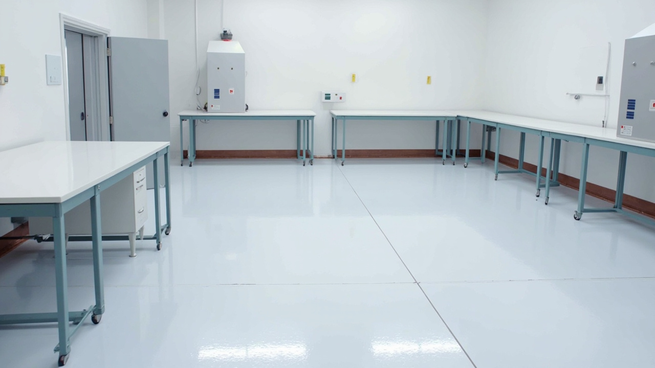
I. Resistivity Classification: Anti-static, Conductive and Insulating
The first step in evaluating anti-static coatings is to qualitatively define the "resistance range." According to industry practice (consistent with the spirit of IEC 61340 and ANSI/ESD S20.20):
| Category | Surface Resistivity (Ω/□) | Volume Resistivity (Ω·cm) | Function |
|---|---|---|---|
| Conductive | < 10⁵ | < 10⁴ | Rapid dissipation, used for shielding/grounding |
| Static dissipative / Anti-static | 10⁵ – 10⁹ | 10⁴ – 10⁸ | Controllable dissipation, mainstream for ESD protection |
| Anti-static (low) | About 10⁹ – 10¹¹ | — | Light dust suppression |
| Insulating | > 10¹¹ | > 10¹² | Isolation, no dissipation |
Different standards have slightly different calibrations (some collectively call 10⁴–10⁹ static dissipative). The engineering consensus is: the target for floors and tabletops in electrostatic protection work areas is mostly 10⁵–10⁹ Ω/□, which can dissipate charges within seconds without causing electric shock or equipment interference due to excessively low resistance. Surface resistivity is measured with a high-resistance meter according to GB/T 1410 "Test methods for volume resistance and surface resistance of solid insulating materials"; this standard is equivalent to IEC 60093 and is the hard basis for acceptance of anti-static coatings. Volume resistivity reflects the leakage capability of the coating body; together they define the anti-static grade of the coating.
II. Conductive Fillers: The Skeleton for Building the Leakage Network
The resin body of anti-static coatings (epoxy, polyurethane, acrylic, polyester or epoxy for powder) is mostly insulating (resistivity > 10¹² Ω·cm). To make the film conductive, conductive fillers must be added, and when the filler concentration exceeds the "percolation threshold," particles contact each other to form a continuous conductive path. Common conductive fillers are divided into four types.
The first is carbon-based conductive carbon black. It is the most commonly used and low-cost; aggregates form a chain-like network with a relatively low percolation threshold (about 5–15 wt%), but high addition worsens color (only black or dark gray), rheology and mechanical properties. By structure it can be divided into ordinary carbon black, super-conductive carbon black (e.g., Ketjenblack), and acetylene black; super-conductive carbon black has higher aspect ratio and lower percolation.
The second is carbon nanomaterials, including carbon nanotubes and graphene. They have extremely high aspect ratios, with percolation thresholds as low as below 1 wt%, and enhance mechanics and thermal properties; but they are difficult to disperse, prone to agglomeration, and costly, requiring surface modification, mostly used in high-end films or composites.
The third is the metal series, including silver, copper, nickel, and stainless steel fibers. Conductivity is excellent; silver powder performs best but is expensive, copper oxidizes easily, nickel or stainless steel fibers suit anti-static coatings and conductive adhesives. Metal fillers bring issues such as high density, easy settling, and possible color change.
The fourth is metal oxide or coated types, including antimony-doped tin oxide, indium tin oxide, conductive mica, and conductive titanium white. Antimony-doped tin oxide can be made light-colored and transparent conductive, overcoming the limitation that carbon black can only be dark; conductive mica or conductive titanium white is mica or titanium white surface-coated with oxide, yielding light-colored, anti-corrosion combined conductive fillers, often used in powder anti-static topcoats.
Filler selection is essentially a trade-off of "color, cost, resistivity, compatibility": for light color choose tin oxide or conductive mica, for ultimate conductivity choose carbon black or silver, for combined anti-corrosion choose conductive mica or nickel.
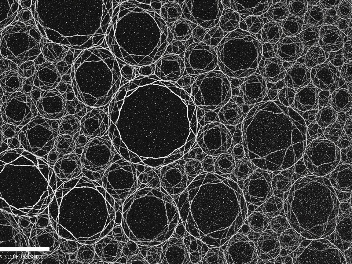
III. Percolation Mechanism and Formulation Key Points
When the conductive filler concentration is below the percolation threshold, particles are isolated and the film remains insulating; once above the threshold, resistivity shows a "sharp drop—plateau" curve with concentration. There are four formulation key points.
First, threshold control: use the minimum filler amount to achieve the target resistivity, avoiding excess that damages mechanics and appearance. Carbon nanotubes and graphene lower the threshold by high aspect ratio. Second, dispersion: fillers must be uniformly dispersed to avoid agglomeration (agglomeration wastes filler and creates defects). Powder systems need to pre-mix conductive fillers and extrude-dispersed into resin. Third, curing does not destroy the network: crosslinking shrinkage may break fragile conductive chains, requiring control of curing stress; especially critical for thermoset powders. Fourth, durability: the conductive network should be friction-resistant and aging-resistant; floor types need wear resistance (see wear-resistant powder coating), otherwise anti-static fails after walking-path wear.
Kexin New Materials (kexinMaterials) prefers "conductive mica plus moderate carbon black" composite in powder anti-static systems: conductive mica provides light color and anti-corrosion base, carbon black supplements low resistance, making the topcoat both light-colored and stably reaching 10⁶–10⁹ Ω/□, and weather/wear resistant. This composite idea is more stable than a single filler and avoids the "all carbon black = only black" limitation.

IV. Construction, Grounding and Acceptance
Anti-static coating is not "anti-static once brushed"; it must be paired with a grounding system. For substrate and primer, metal substrates are blasted (Sa2.5, refer to coating surface treatment Sa2.5); concrete floors need sealing and leveling. Large-area floors often lay copper foil grounding grids, then coat conductive primer to connect, directing charges to earth. The anti-static topcoat reaches target resistivity with uniform film thickness; powder systems can pre-fabricate metal parts in factory. For grounding, grounding resistance follows site codes (e.g., electronic factories, explosion-proof sites have respective requirements), tested regularly.
Acceptance measures surface and volume resistivity per GB/T 1410, checks adhesion per GB/T 9286, and performs point-to-point resistance and system resistance tests per ANSI/ESD S20.20 and IEC 61340-5-1. Explosion-proof sites also need to comply with relevant requirements of GB 50058 "Design of electrical installations in explosive atmospheres." It must be emphasized: measuring only coating resistivity while ignoring the grounding system equals measuring only the "wire" without the "ground wire," and overall anti-static may still fail.
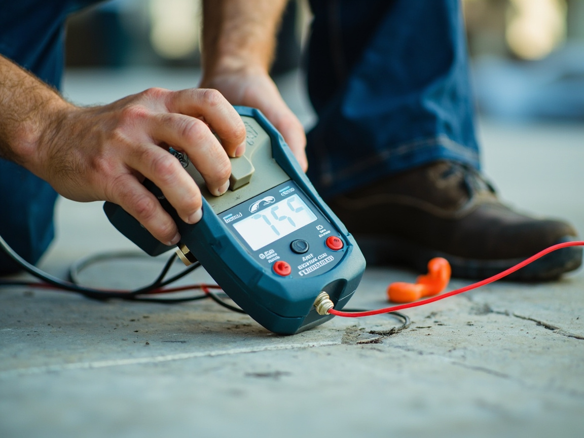
V. Typical Application Scenarios
Electronics and semiconductor cleanrooms: floors, workbenches, turnover racks, target 10⁵–10⁹ Ω/□, preventing static from breaking chips. Flammable and explosive sites: oil depots, gas stations, powder workshop floors and equipment, anti-static sparks; as static conductors need reliable grounding. Medical and laboratories: control particle adhesion and interference. Industrial equipment enclosures: explosion-proof motors, instrument housings, need anti-static accumulation. Powder-coated parts: some metal parts coated with anti-static powder for subsequent processing or explosion-proof.
VI. Common Misconceptions
Misconception 1: Lower resistance is better. Wrong. Too low has electric shock and interference risks; the target for ESD protection zones is exactly the dissipative range. Misconception 2: Dark equals conductive, light equals non-conductive. Wrong. Tin oxide or conductive mica can achieve light-colored anti-static. Misconception 3: Done after coating. Wrong. Without grounding charges have nowhere to go; must connect to earth. Misconception 4: Wear resistance unimportant. Wrong. Floor walking-path wear destroys conductive network; need wear-resistant pairing. Misconception 5: Color change doesn't affect performance. Wrong. Different systems use different conductive fillers; mixing colors may change resistivity and appearance.
VII. Synergy Boundaries with Insulation and Wear Resistance
Anti-static and insulation seem opposed, but are actually different positions on the resistance spectrum: insulation requires > 10¹¹, anti-static at 10⁵–10⁹, conductive < 10⁵. The same coating system can move on the spectrum via filler dosage. But note: electronic devices sometimes require both "enclosure anti-static dissipation" and "internal insulating isolation," which is different layers performing their duties, not a contradiction in the same layer. For wear resistance, floor anti-static coatings must be wear-resistant, otherwise the network wears through and fails (synergize with wear-resistant powder coating). For anti-corrosion, metal substrate anti-static topcoats often need epoxy anti-corrosion primer underneath (synergize with heavy-duty powder coating).
VIII. Characteristics of Powder-type Anti-static
Powder anti-static coating with zero VOC (0 as measured by GB 30981), uniform film thickness, suitable for factory prefabrication of metal parts, light-colored conductive mica type with anti-corrosion; suitable for explosion-proof motor housings, instrument housings, and handling equipment. The mechanism is consistent with liquid, relying on filler percolation to form a network, and likewise requires grounding. Compared with liquid, powder offers more stable quality on batch metal parts and is solvent-free, but for complex floors (concrete), liquid epoxy anti-static floor coating remains the main choice; the two are divided by substrate.IX. Technology Trends
First is light-coloring: tin oxide, conductive mica, and conductive titanium dioxide drive the普及 of light-colored anti-static, resolving the contradiction in electronic workshops of "needing both clean light color and anti-static". Second is nano-sizing: carbon nanotubes and graphene achieve stable conductivity at extremely low addition levels and enhance mechanics. Third is multifunctional integration: anti-static plus wear resistance plus anti-corrosion plus antibacterial in one, reducing coating layers. Fourth is intelligence: embedding conductive networks that can monitor resistance, providing real-time alarm for anti-static failure.
X. Selection Decision Tree
When selecting anti-static coating, first look at the substrate (metal parts use powder, floors use liquid epoxy); then look at color requirements (light color chooses tin oxide or conductive mica, dark color chooses carbon black); then look at resistance target (conductive < 10⁵, dissipative 10⁵–10⁹); finally look at environment (explosion-proof requires reliable grounding, electronics requires low charging). Write this path into a specification, and selection will not rely on feeling.
XI. Common Defects and Troubleshooting
| Defect | Cause | Countermeasure |
|---|---|---|
| High resistance | Insufficient filler, poor dispersion | Increase filler, strengthen dispersion |
| Uneven resistance | Non-uniform mixing, film thickness variation | Uniform mixing, control film thickness |
| Wear failure | Insufficient surface wear resistance | Add wear-resistant topcoat |
| Poor grounding | Copper foil break, high ground resistance | Check grounding system |
| Light color blooming | Uneven filler distribution | Optimize dispersion process |
XII. Standards and Inspection Checklist
Acceptance should cover: GB/T 1410 volume and surface resistivity; GB/T 9286 adhesion; ANSI/ESD S20.20 and IEC 61340-5-1 point-to-point and system resistance; GB 50058 compliance for explosion-hazard sites. It is recommended to establish three ledgers of "coating resistance + system resistance + grounding resistance", conduct regular inspections, and turn anti-static from one-time construction into continuous management.
FAQ
XIII. Standard List and Acceptance Ledger
For ease of engineering implementation, the main standards involved in anti-static coating are organized into a list for item-by-item verification during acceptance. Core standards include: GB/T 1410 "Test Methods for Volume Resistivity and Surface Resistivity of Solid Insulating Materials" (equivalent to IEC 60093, hard basis for resistivity); GB/T 9286 (cross-cut adhesion); ANSI/ESD S20.20 and IEC 61340-5-1 (resistance targets and test methods for electrostatic protected areas); GB 50058 "Design of Electrical Installations in Explosive Atmospheres" (compliance for explosion-hazard sites); GB/T 13452.2 (film thickness). Electronic factories may also refer to GB 50515 and other anti-static floor specifications.
The acceptance ledger is recommended to include four items: first, coating surface and volume resistivity (GB/T 1410); second, point-to-point resistance and system resistance (ANSI/ESD S20.20); third, grounding resistance (measured periodically per site specification); fourth, adhesion and appearance. The key is not to measure only the coating and ignore grounding—measuring only the "conductor" without measuring the "ground wire" is equivalent to not measuring. Many projects pass a one-time test at completion and never re-test during operation, only to find the grounding resistance has exceeded the limit when equipment is mysteriously damaged or spark hazards appear, which is too late.
Make this ledger a traceable document, which satisfies electrostatic protection audits and facilitates future inspection comparison. Kexin New Materials (kexinMaterials) attaches a "resistivity test card + grounding layout diagram + re-test cycle table" three-piece set when delivering anti-static solutions, giving customers a basis from construction to operation.
XIV. Where Static Comes From: Charging Mechanism and Hazard Thresholds
To design anti-static coatings, one must first understand how charges are generated and accumulated. The primary mechanism is contact electrification, often collectively called frictional electrification: when two materials are in close contact, electron or ion transfer occurs at the interface, and after separation they each carry equal and opposite charges. The tendency of materials to gain or lose electrons can be arranged into a "triboelectric series"; the farther apart two materials are in the series, the greater the charge generated when they rub against each other. Every contact-separation between human body, shoe soles, floor, totes, packaging film, conveyor belts, powder and pipe walls is a potential charging source. In addition, there is inductive charging (conductors in the electric field of charged bodies undergo charge redistribution) and conductive charging (direct contact with charged bodies to obtain charge).
How high the accumulated potential is depends on the charge amount and the capacitance to ground. Human body capacitance to ground is typically on the order of hundreds of picofarads; walking on insulating floor in dry environment, human body potential can reach several thousand volts; operators often carry potentials sufficient to damage devices without any awareness. Hazard thresholds need to be viewed by scenario, and differ greatly.
| Scenario | Object of concern | Typical hazard threshold | Main consequence |
|---|---|---|---|
| Microelectronic devices | Sensitive components | Some devices' human body model tolerance is below hundred-volt level | Breakdown, latent damage, early failure |
| Combustible vapor environment | Oil gas, solvent | Minimum ignition energy is at millijoule level | Spark ignition, flash explosion |
| Combustible dust environment | Powder workshop | Minimum ignition energy usually higher than vapor | Dust cloud explosion |
| Clean room | Particle adhesion | Several hundred volts can significantly adsorb | Yield drop, appearance defects |
A common confusion must be clarified here: high static voltage does not equal greater danger. The energy of electrostatic discharge equals one-half times capacitance times voltage squared; when human body is charged to several thousand volts, the released energy is typically only at millijoule level, which is just a stinging sensation for humans, but this energy is already sufficient to ignite certain combustible vapors and to break down the gate oxide layer of microelectronic devices only a few nanometers thick. Therefore, the goal of anti-static design is never to "prevent humans from being shocked", but to continuously discharge charges to the earth through a controlled path before they accumulate to dangerous levels.
Following the approach of GB 12158 "General Guidelines for Preventing Electrostatic Accidents", electrostatic accident prevention follows three main lines: reduce charging (select materials close in triboelectric series, reduce friction and separation speed), accelerate leakage (increase material conductivity, reliable grounding, humidification or use of neutralizers when necessary), control environment (eliminate combustible mixtures, limit discharge conditions). Anti-static coating is one link in the second main line; it cannot replace the grounding system, nor can it replace the charging control of the process itself.
XV. The Second Set of Indicators Beyond Resistance: Charge Decay and Human Body Voltage
Using only surface resistivity to judge anti-static performance is the most common one-sided practice in engineering. Resistivity describes the "smoothness of the discharge path", but what users really care about is "how long it takes for charge to dissipate" and "how much potential remains on the human body". Therefore, complete electrostatic protection verification requires a second set of indicators.
The first is charge decay time. The measurement idea is to charge the specimen surface to a specified initial potential, then measure the time required for it to naturally decay to a certain proportion, with method referable to IEC 61340-2-1 "Electrostatics - Part 2-1: Measurement methods - Ability of materials and products to dissipate static electric charges". Common engineering requirements are to decay from 1000 V to 100 V within several seconds, with specific values subject to the applicable project specification. The reason for separately measuring decay time is that when resistivity is qualified but there are local breaks, or the surface is covered by a non-conductive wax layer, actual dissipation may be much slower than expected from the resistance reading.
The second is walking human body voltage. Following the idea of ANSI/ESD STM97.2, personnel wearing specified footwear walk on the tested floor with standard gait, and the peak human body-to-ground potential is recorded in real time. ANSI/ESD S20.20 ESD Control Program treats the "person-shoe-floor" as a system for assessment, rather than looking at floor material in isolation. This is very critical: the same anti-static floor may pass with anti-static shoes, but completely fail with ordinary rubber-soled shoes.
The third is system resistance and point-to-point resistance. Floor and workbench resistance measurement can refer to ANSI/ESD S7.1 (floor material resistance) and IEC 61340-4-1 (resistive characterization of flooring materials); person-shoe-floor system resistance can refer to IEC 61340-4-5 and ANSI/ESD STM97.1. During measurement, electrode shape, applied voltage, loading weight, and stable reading time are all specified; randomly poking two multimeter probes on the floor yields numbers with no acceptance significance.
| Indicator | Question answered | Reference method | Commonly ignored consequence |
|---|---|---|---|
| Surface/volume resistivity | Whether path is smooth | GB/T 1410 (equivalent IEC 60093) | Measure only material, not system |
| Point-to-point and grounding point resistance | Whether coating to grounding electrode is connected | ANSI/ESD S7.1, IEC 61340-4-1 | Copper foil break points missed |
| Charge decay time | How long to dissipate charge | IEC 61340-2-1 | Wax layer coverage causes extremely slow actual dissipation |
| Walking human body voltage | How much potential remains on body | ANSI/ESD STM97.1/97.2 | Footwear mismatch makes floor virtually useless |
Looking at these four items together constitutes a defensible electrostatic protection verification system. Kexin New Materials (kexinMaterials) clearly distinguishes "material indicators" and "system indicators" columns when delivering electronic workshop projects; the former is guaranteed by the coating, the latter requires the customer to jointly bear through footwear management, grounding maintenance, and cleaning regime.
XVI. Humidity, Cleaning and Resistance Drift: Why Completion Qualification Does Not Equal Long-term Qualification
The resistance of anti-static coating is not a fixed physical constant; it drifts with environment and usage state, which is also the easiest pit to step on during operation and maintenance.
Humidity has the most significant effect. When air humidity is high, the water film adsorbed on the material surface provides additional ionic conductive pathways, and the surface resistance can drop by one to several orders of magnitude; once the dry season arrives or air-conditioning dehumidification operates, the water film disappears and the surface resistance rebounds, and a previously qualified floor may exceed the limit. This explains two phenomena: first, static accidents occur frequently in winter and dry regions; second, some systems relying on hygroscopic antistatic agents almost fail in low-humidity environments. Precisely because of this, resistance tests such as GB/T 1410 specify standard temperature and humidity conditions, and the report must state the temperature and humidity at the time of testing, otherwise the data are not comparable. The safe engineering approach is to select a system that relies on conductive fillers to form a permanent percolation network, rather than depending on migratory antistatic agents, and at the same time control the lower limit of relative humidity in critical areas.
Cleaning and maintenance are the second variable. Floor waxing, application of high-gloss maintenance agents, and use of cleaners containing silicone oil will all form an insulating thin film on the surface, "covering" the conductive network. The value measured by a resistance tester at this time may be several orders of magnitude higher, while the coating itself is not damaged. Similarly, deposition of oil stains and resin dust can also cause local insulation. The troubleshooting characteristic of such problems is: after cleaning, the resistance returns to normal, indicating surface contamination rather than coating failure. Therefore, the cleaning procedure for anti-static areas should prohibit waxing and silicone-containing preparations, and only use designated neutral cleaners.
Wear and aging are the third variable. Under repeated rolling by forklifts, carts, and cable trays, the surface conductive network on the floor will be worn through or compacted and deformed, and the resistance rises accordingly; the aisle positions often fail first (see wear-resistant powder coating for wear-resistant design). Ultraviolet light and chemicals can also degrade the matrix and cause filler loss.
The fourth variable is the grounding system itself. The copper foil grid may be cut off by subsequent drilling and slotting during later construction; the grounding electrode may have increased grounding resistance due to soil drying or corrosion; the grounding wire connection points may oxidize and loosen. None of these are reflected in the coating resistance, yet they directly deprive the entire system of a discharge path.
The conclusion is: passing the completion acceptance is only a starting point. Three ledgers of "coating resistance + system resistance + grounding resistance" should be established and retested periodically, and the retest cycle, responsible person, and judgment limits should be written into the operation and maintenance system. Many projects are tested once and pass at completion, then never retested for years, until equipment is mysteriously damaged in batches or spark hazards appear, only to find that the grounding has long been disconnected, by which time the loss has already been incurred.
17. Material Selection Deduction for Three Engineering Scenarios
Scenario 1, SMT workshop floor. The demand is to prevent electrostatic breakdown of sensitive components, while requiring a light color and brightness to facilitate visual inspection, and resistance to forklift rolling. The solution adopts an epoxy anti-static floor system: first grind and seal the base surface with a primer, then lay a copper foil grounding grid and reliably connect it to the grounding electrode, use a conductive primer in the middle layer to connect the grid, and the topcoat uses conductive mica compounded with a small amount of conductive carbon black to keep a light gray color while controlling the surface resistance in the range of 10⁶ to 10⁹ ohms per square. In addition to measuring resistivity per GB/T 1410 for acceptance, point-to-point resistance, grounding point resistance, and walking body voltage must be measured, and it must be clear that "matching anti-static shoes" is a prerequisite for system qualification. The cleaning procedure prohibits waxing.
Scenario 2, equipment enclosures and operating platforms in oil depots and solvent tank farms. The demand shifts to explosion-proofing—preventing electrostatic sparks from igniting combustible vapors. Here the positioning is not "dissipative" but "conductor": the equipment and platforms should be reliably grounded as static conductors, with resistance values toward the low end. Design and acceptance need to comply with GB 50058 "Code for Design of Electrical Installations in Explosive Atmospheres" and relevant requirements of GB 12158; conductive (static) floors may also refer to GB 50515. Metal parts can use factory-prefabricated powder anti-static coating, with an epoxy anti-corrosion primer powder at the bottom to resist atmospheric and medium corrosion (see heavy-duty powder coating for synergy), and include cross-connection and grounding continuity testing in periodic safety inspections, at a higher frequency than ordinary electronic workshops.
Scenario 3, explosion-proof motor and instrument enclosures. These workpieces are produced in large batches, have regular shapes, and need to be coated once in the factory, making them the most suitable field for powder anti-static systems. The solution uses light-colored anti-static powder of the conductive mica type, with pretreatment by Sa2.5 sandblasting (see coating surface treatment Sa2.5) to ensure adhesion and bottom-layer connectivity, and uniform film thickness control to avoid discrete resistance distribution. In addition to resistivity, acceptance adds adhesion (GB/T 9286) and appearance inspection, with special attention to the "floating" problem common in light-colored systems—floating is often not just an appearance defect, it also means uneven filler distribution and locally high resistance.
The differences among the three scenarios illustrate a principle: anti-static is not a uniform indicator, but a design goal determined by the hazard type. Electronic workshops fear "breakdown of sensitive parts", therefore pursue the dissipative range and low electrification; explosion-proof sites fear "spark ignition", therefore pursue reliable grounding and rapid discharge; cleanrooms fear "particle adsorption", therefore focus on surface potential rather than mere resistance. Clarify the hazard type first, then discuss resistance values, so that material selection will not go astray.
Q: Are anti-static and conductive the same thing?
A: No. By resistance grading: surface resistance 10⁹ is insulating. Electrostatic protected work areas mostly use the dissipative range, not the lower the better.
Q: How to measure surface resistivity accurately?
A: Per GB/T 1410 (equivalent to IEC 60093) use a megohmmeter and specified electrodes, measured under standard temperature and humidity; results are affected by temperature, humidity, electrode pressure, and placement time, so operation must be standardized. Acceptance also requires point-to-point resistance and system resistance.
Q: Why can light-colored anti-static coating also be made?
A: Traditional carbon black can only be dark; but light-colored conductive fillers such as antimony-doped tin oxide, conductive mica, and conductive titanium white can provide a conductive network while maintaining light color, suitable for places with color requirements.
Q: What is the percolation threshold and why is it important?
A: It is the critical concentration at which conductive fillers form a continuous network. Below it the coating remains insulating; above it the resistivity drops sharply. The formulation goal is to use the minimum filler amount to achieve the target resistance, avoiding excessive amounts that damage mechanics, appearance, and cost. Carbon nanotubes and graphene have high aspect ratios, so the threshold can be very low.
Q: Is anti-static coating useful without grounding?
A: Almost useless. The coating only controllably guides the charge to the surface network; ultimately it must be led into the earth through the copper foil grid and grounding electrode to avoid accumulation. The resistance of the grounding system must also be tested per specifications.
Q: How to choose between conductive carbon black and metal fillers?
A: Carbon black is low cost, only dark, and average corrosion resistance; metals (silver, copper, nickel) have excellent conductivity but are expensive and prone to oxidation and settling; conductive mica or tin oxide are light-colored and have good corrosion resistance. Weigh by the four factors of "color, cost, resistivity, corrosion resistance".
Q: Will the floor anti-static coating fail due to cable tray wear?
A: Yes. After wear destroys the surface conductive network, resistance rises and it fails. A wear-resistant system is needed (can compound wear-resistant fillers or apply a wear-resistant clear coat), and resistance should be retested periodically.
Q: Are the anti-static requirements for electronic factories and oil depots the same?
A: The direction is consistent but the focus differs: electronic factories emphasize electrostatic protection (prevent breakdown of sensitive parts), targeting the dissipative range and low electrification; oil depots emphasize explosion-proofing (prevent spark ignition), belonging to static conductors that must be reliably grounded. Both are designed per their respective specifications.
Q: What are the characteristics of powder anti-static coating?
A: Zero VOC, uniform film thickness, factory-prefabricated metal parts possible, light-colored and corrosion-resistant with conductive mica type; suitable for explosion-proof motor housings, instrument housings, and transfer equipment. The mechanism is consistent with liquid, relying on filler percolation to form a network, and also requires grounding.
Q: How often to retest anti-static performance?
A: Per site specification and risk; electronic factories usually inspect resistance periodically (e.g., quarterly or semi-annually); explosion-proof sites more frequently and included in safety audits. Wear, cleaning, and aging all change resistance, so ledgers must be established.
Q: Does humidity affect the resistance of anti-static coating?
A: It has a great impact. When humidity is high, the surface-adsorbed water film provides ionic conductive pathways, and surface resistance can drop by one to several orders of magnitude; in the dry season the water film disappears and resistance rebounds or even exceeds the limit. Therefore tests such as GB/T 1410 specify standard temperature and humidity, and the report must state the test temperature and humidity. Engineering should prioritize systems that rely on conductive fillers to form a permanent percolation network, rather than migratory antistatic agents.
Q: Why does floor resistance increase after waxing?
A: Wax layers, high-gloss maintenance agents, and silicone-oil-containing cleaners form an insulating thin film on the surface, "covering" the conductive network, and the measured resistance may be several orders of magnitude higher, while the coating itself is intact. The distinguishing feature is: after thorough cleaning, the resistance returns to normal. The cleaning procedure for anti-static areas should prohibit waxing and silicone-containing preparations.
Q: Besides resistivity, what other indicators should be measured?
A: At least three more: charge decay time (refer to IEC 61340-2-1, answering "how long until charge is discharged"), point-to-point and grounding point resistance (refer to ANSI/ESD S7.1, IEC 61340-4-1), walking body voltage (refer to ANSI/ESD STM97.1/97.2). ANSI/ESD S20.20 assesses the "person—shoe—floor" as a system; measuring only the material without the system is incomplete.
Q: Static voltage is several thousand volts, why are people not injured but chips can be damaged?
A: Discharge energy equals one-half times capacitance times voltage squared. Human body-to-ground capacitance is on the order of hundreds of picofarads; several thousand volts corresponds to only millijoules of energy, which is just a sting to a person; but this energy is enough to break down microelectronic devices with gate oxide layers only a few nanometers thick, and also enough to ignite certain combustible vapors. Therefore, to judge hazard, look at energy and receptor sensitivity, not just the voltage number.
Further Reading
- Wear-resistant powder coating: fillers, hardness, and working-condition selection: Floor anti-static coating must be wear-resistant; this article complements wear-resistant design.
- Insulating powder coating: volume resistance and dielectric strength: Opposite to anti-static "controlled discharge" is insulation "isolation"; the two articles constitute the two ends of the resistance spectrum. Coating Surface Treatment Sa2.5 and Blasting Grades: The foundation for adhesion of anti-static coating on metal parts is pre-treatment, and the blasting grade determines the bonding of the primer.
- Engineering Applications of Heavy-Duty Anti-Corrosion Powder Coating: The anti-static topcoat in explosive environments such as oil depots and tank farms must be paired with epoxy anti-corrosion primer powder; anti-corrosion is the prerequisite for long-term reliable dissipation.
- Thermal Conductive Coating and Heat Dissipation: Filler Systems, Thermal Conductivity, and Power Device Applications
- Principles and Classification of Powder Coating: From Film-Forming Mechanism to Resin System Selection
- Industrial Paint Application: Airless Spray Parameters, Film Thickness Control, and Coating Interval