On high-temperature pipelines, engine peripheral components, electric heating appliances, exhaust pipes, and auxiliary structures of industrial kilns, organic coatings often first yellow, chalk, crack, and even carbonize due to insufficient heat resistance. Nano-ceramic and inorganic-organic hybrid coatings, with their dense ceramic phase and excellent thermal stability, are becoming important candidates for such high-temperature working conditions. But behind promotional terms like "heat resistant to 600°C" and "thermal shock resistant", engineering needs to answer: does heat resistance refer to continuous service temperature or instantaneous peak? Why does thermal shock cause cracking? How to manage the coefficient of thermal expansion difference (CTE) between coating and substrate? This article systematically reviews the engineering logic of temperature resistance and thermal shock of nano coatings from mechanisms, standards, real data to selection boundaries.

I. Continuous Service Temperature, Peak Temperature and Thermal Degradation Mechanism
The first concept to distinguish when discussing coating temperature resistance is continuous service temperature and instantaneous/peak temperature. The former is the upper limit at which the coating can remain stable over a long period (e.g., thousands of hours) without irreversible chemical/physical degradation; the latter is the limit that appears briefly and allows slight changes but does not cause failure. A responsible temperature resistance specification should give both, e.g., "continuous service -50~400°C, short-term can reach higher".
The heat resistance bottleneck of organic resins lies in the thermal-oxidative aging of molecular chains: rising temperature accelerates free radical chain scission, oxidation, and crosslink network rearrangement, manifesting macroscopically as yellowing, gloss loss, chalking, decreased adhesion, and ultimately carbonization and flaking. Nano ceramic coatings (SiO₂, TiO₂, inorganic silicates, etc.) are dominated by inorganic networks, with thermal decomposition temperatures far higher than pure organic resins, thus significantly improving continuous service temperature. However, most actual products are "inorganic-organic hybrid" — using a small amount of organic components to improve flexibility and workability, which brings a trade-off: the lower the organic phase ratio, the higher the temperature resistance, but brittleness often increases and adhesion control becomes more difficult.
According to publicly available TDS excerpts from our research archive: a hydrophobic self-cleaning nano composite ceramic coating (YC-8703) has a long-term service temperature of -50°C—400°C, and can be accelerated cured by baking at 150°C for 30 min; a SiO₂-based automotive ceramic coating (Gaamp360) is heat resistant up to 600°C; an inorganic nano ceramic composite car paint coating (Re-yingcai) is heat resistant from -45°C—180°C; a Si-based automotive ceramic shield (Onyx) does not give a clear upper temperature limit. It can be seen that the temperature resistance span of different systems varies greatly; when selecting, one must never only look at the word "heat resistant", but at the specific values and test conditions.
II. Why Thermal Shock Is More Dangerous Than Simple High Temperature
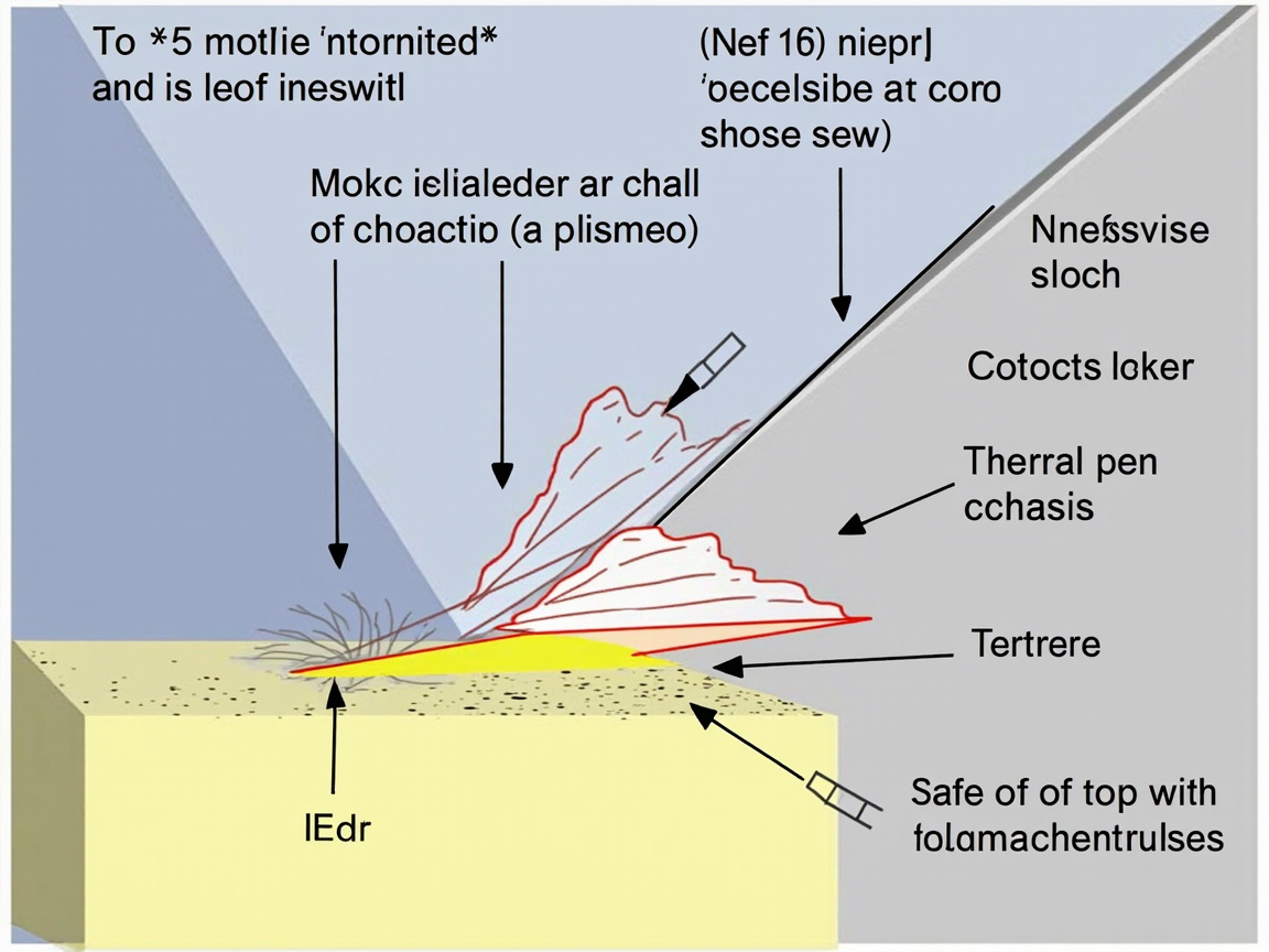
Many coatings can "withstand" constant high temperature, but crack and flake under cold-hot alternation, because of thermal shock — rapid temperature changes induce transient thermal stress within the coating/substrate system. When a workpiece is rapidly cooled from high temperature (e.g., 400°C) to room-temperature water or low-temperature environment, the surface contracts rapidly while the interior is still in an expanded state, and the surface layer bears tensile stress; conversely, during rapid heating the surface layer is under compression. If the thermal stress exceeds the coating's own fracture toughness or film-substrate bond strength, microcracks, crazing, and even whole-sheet flaking will occur.
The sensitivity of thermal shock failure is dominated by two factors:
- Coefficient of thermal expansion difference (CTE mismatch). The closer the linear expansion coefficients of coating and substrate, the more synchronized their expansion and contraction during temperature changes, and the smaller the interfacial shear stress. Typical engineering reference values (order of magnitude from common material manuals, for qualitative judgment): carbon steel about 11–13×10⁻⁶/K, aluminum about 23×10⁻⁶/K, while ceramic/SiO₂ type coatings are often below 10×10⁻⁶/K or even smaller. The difference between metal substrates (especially aluminum) and low-CTE ceramic layers is one of the main sources of thermal shock cracking.
- Thermal conductivity and thickness. Thin layers (nm–µm) respond quickly to temperature and have small self-thermal stress, but interfacial stress still depends on CTE difference; thick films can insulate heat, but may bear greater gradient stress due to large internal-external temperature difference.
Therefore, "thermal shock resistance" is not a single material property, but a system performance jointly determined by "coating CTE × substrate CTE × thickness × heating/cooling rate × temperature difference". When claiming thermal shock resistance, it must be stated under what temperature difference, how fast a rate, and on what substrate it was verified.
Further, there is a easily overlooked form of thermal shock failure called "thermal fatigue": it does not crack from a single rapid cooling and heating, but under thousands of small-amplitude thermal cycles, interfacial microcracks gradually initiate, propagate, and interconnect, eventually suddenly penetrating and flaking after a certain cycle. This progressive failure is especially typical for equipment with long-term start-stop (such as electric heating tubes, engine peripherals, kiln doors); its danger lies in the intact appearance in the early stage, difficult to detect by visual inspection, and when flaking occurs, it is often accompanied by local corrosion or heat dissipation failure. Therefore, evaluating thermal shock should not only look at "whether it can survive one large temperature difference", but more at "how many actual-amplitude cycles it can survive". Using cycle count as an acceptance indicator is closer to real life than a single temperature difference peak. This is also why in the previous checklist, the thermal shock cycle curve is listed as a must-check item for high-temperature conditions — it directly corresponds to the actual start-stop rhythm of equipment, and is one of the most reliable inputs for predicting field life. Ignoring thermal fatigue and only staring at static temperature resistance is the most common and easily misjudged root cause of early field failure of high-temperature nano coatings. Writing thermal fatigue cycles into clauses in engineering acceptance can significantly reduce rework rates and warranty disputes.
III. Evaluation Standards and Test Logic for Temperature Resistance and Thermal Shock
The evaluation of coating heat resistance already has mature methods in national and international standards, but there is no single global mandatory dedicated standard for "nano coating temperature resistance/thermal shock", and the industry mostly references existing coating and material standards (consistent with the "Market and Standards Status" section of the research archive). Commonly referenced include:
- ISO 3248 "Paints and varnishes — Determination of the effect of heat on paint films": place painted panels at a specified high temperature for a certain time, then after cooling check for discoloration, blistering, cracking, chalking, adhesion changes, to evaluate stability under high temperature.
- GB/T 1735 "Determination of heat resistance of paint films": commonly used domestically, place panels in a forced-air constant-temperature oven at specified temperature and time, then observe surface changes of the paint film (cracking, blistering, discoloration, detachment).
- ASTM D2485 series (coating evaluation for specific industrial environments), etc., can be used as supplementary context; for plastic/elastic substrates, the heat deflection temperature (HDT) boundary must also be considered.
- Thermal shock cycling is mostly executed per customer specification or industry practice: e.g., "high temp T₁ hold t₁ → rapid cool to T₂ (water/room-temp air/liquid nitrogen) → hold t₂ → ramp up", record the cycle count at which failure (cracking, flaking, adhesion dropping to a certain grade) occurs. Temperature difference span, cooling medium, and heating/cooling rate are key variables and must be noted in the report.
Note: many "600°C resistant" labels on the market do not disclose whether it is continuous service or thermal shock peak, nor specify substrate and heating/cooling curve. Rigorous acceptance should require the supplier to provide a third-party report with standard number and complete conditions, rather than relying solely on promotional numbers.
IV. Interpretation of Real Temperature Resistance and Thermal Shock Resistance Data
The temperature resistance information cited from the research archive is organized below for easy cross-boundary viewing:
| Product (per manufacturer TDS, excerpted from this research archive) | System | Temperature resistance statement | Thermal shock resistance / related notes |
|---|---|---|---|
| YC-8703 composite ceramic coating | Single-component nano composite ceramic | Long-term service -50~400°C | Explicitly "cold-hot shock resistant / thermal shock resistant"; can be fast cured by baking at 150°C for 30 min |
| Gaamp360 ceramic coating | SiO₂-based (optional graphene/TiO₂) | Heat resistant up to 600°C | Chemical resistant pH 2–12; no separate thermal shock cycle count listed |
| Re-yingcai YCC05006G | Inorganic nano ceramic composite | -45~180°C | Superhydrophobic, UV-resistant weatherability; substrate is original car paint/color change film/car wrap |
| Onyx Nano Shield | Si-based automotive ceramic shield | No clear upper limit | Durability about 1 year; suitable for paint/plastic/aluminum/chrome/wheel hubs |
From this table, the selection key points can be read: if the working condition is around the engine compartment, exhaust pipe heat shield, etc., long-term 300–600°C environment, priority should be given to SiO₂-based systems like Gaamp360 that are explicitly rated to 600°C, and further request thermal shock cycle reports; if it is automotive paint maintenance (-45~180°C already covers most climates and sunlight conditions), Re-yingcai and Onyx types focus more on hydrophobicity and UV resistance rather than extreme heat resistance; if industrial kiln auxiliary structures need -50~400°C and emphasize cold-hot shock, YC-8703's "thermal shock resistant" statement is more suitable, but it is still recommended to do thermal cycle verification on real workpieces.
V. CTE Matching and Formulation Design: Making "Thermal Shock Resistance" a Controllable Indicator
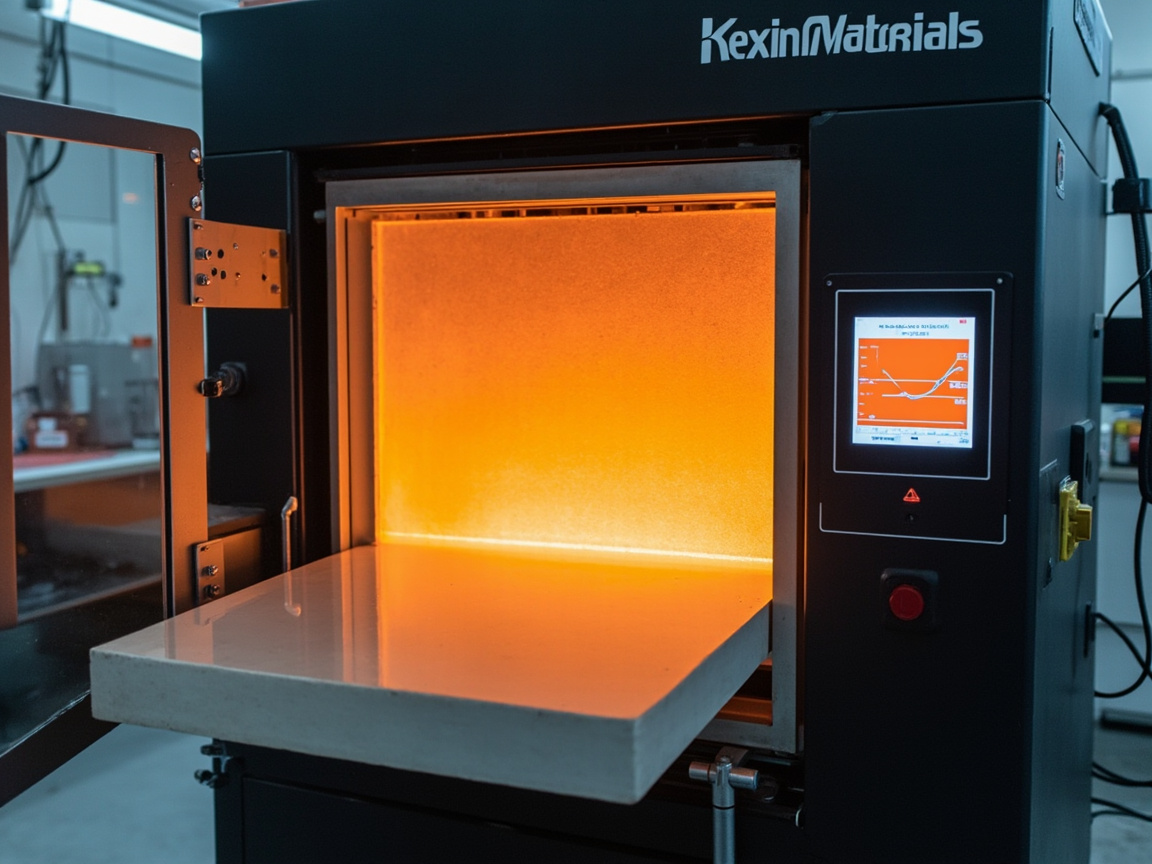
To turn thermal shock resistance from a slogan into a controllable indicator, there are several engineering paths in formulation and process:
- Adjust CTE to approach substrate. By introducing appropriate nano particles (such as nano SiO₂, TiO₂, Al₂O₃) or ceramic phases better matched to the substrate CTE, adjust the overall thermal expansion coefficient of the coating to reduce the difference with the metal substrate. For aluminum substrates (high CTE), it is more necessary to carefully select a low-expansion and flexible hybrid network.
- Control film thickness and gradient. An overly thick coating is more prone to cracking due to gradient stress during thermal shock; most nano coatings are inherently thin (nm–µm), which helps reduce internal stress, but complete coverage without pinholes must be ensured.
- Improve film-substrate adhesion. The higher the cross-cut adhesion (GB/T 9286 / ISO 2409), the better the interface can withstand shear during thermal cycling; surface treatment (e.g., sandblasting Sa 2½, IPA degreasing) is a prerequisite. In the research archive, YC-8703 requires sandblasting above Sa2.5 (46-mesh white corundum is optimal), precisely to lay the foundation for adhesion and subsequent heat resistance performance.
- Toughness balance of hybrid network. Pure inorganic layers have high temperature resistance but are brittle; an appropriate amount of organic phase or flexible segments can absorb thermal stress; the cost is a decrease in continuous temperature resistance, requiring a trade-off at the formulation end.
In the development of high-temperature nano coatings, kexinMaterials suggests that customers provide "substrate type + operating temperature range + heating/cooling rate + expected service life" as a set of inputs to the formulation end, so that we can reverse-design the CTE and thickness, rather than forcibly applying a fixed "heat-resistant 600℃" product to the working condition—because the thermal shock performance of the same coating on steel and aluminum parts may be completely different.

VI. High-Temperature Application Selection Checklist and Acceptance Recommendations
For practical engineering, it is recommended to turn heat resistance and thermal shock requirements into a minimal specification:
- Define temperature range: continuous service temperature (℃) + peak temperature (℃) + single peak duration.
- Define thermal shock conditions: max/min temperature, heating/cooling rate or cooling medium, expected number of cycles.
- Define substrate: steel/aluminum/stainless steel/plastic, and its approximate CTE, for CTE matching evaluation.
- Require standards and methods: heat resistance referenced to ISO 3248 or GB/T 1735; thermal shock with written cycle curve; adhesion per GB/T 9286.
- Request third-party report: complete data with standard number, substrate, film thickness, test conditions, rather than a single word "resistant to 600℃".
When delivering high-temperature application nano coating solutions, kexinMaterials will attach verification recommendations for the above conditions, and emphasize performing pre-acceptance on the customer's real workpiece with no less than one complete thermal cycle period before scaling up to batch coating—this can maximize the avoidance of disconnection between laboratory data and on-site thermal shock performance.
VII. Differences in Nano Particle Types and High-Temperature Resistance Mechanisms
Different nano fillers exhibit different stable behaviors at high temperatures, which directly determine the coating's upper temperature limit and thermal shock performance; the formulation end needs to select particles according to working conditions rather than blindly stacking up temperature resistance numbers.
Silica (SiO₂) has excellent thermal stability and can withstand several hundred degrees Celsius for long periods in ambient air without decomposition, serving as the heat-resistant skeleton of most SiO₂-based ceramic coatings (such as the Gaamp360 system in the research archive with heat resistance up to 600℃); it also provides low CTE and high hardness, but excessive amounts make the coating brittle. Titanium dioxide (TiO₂, especially rutile phase) has outstanding thermal stability and chemical inertness, and can also absorb UV and improve weather resistance, suitable for automotive paint and outdoor structures that require both heat resistance and UV resistance. Alumina (Al₂O₃) and zirconia (ZrO₂) have superior high-temperature resistance and low CTE characteristics, often used in higher temperature or high-toughness scenarios, but have narrower dispersion and application windows.
What needs special distinction is the heat-resistance ceiling of the organic phase in "organic-inorganic hybrid": regardless of how stable the nano ceramic phase is, as long as the formulation contains thermally degradable organic resin, the continuous service temperature is limited by the organic phase. Therefore, the fundamental path to improve temperature resistance is often to reduce the organic phase ratio, or to use higher bond-energy siloxane/silicate networks. The cost is that flexibility and adhesion control to the substrate become more difficult—this is the core trade-off in high-temperature nano coating formulations.
VIII. Quantitative Perspective on Thermal Stress: From Experience to Estimation
Although rigorous failure criteria require experiments, a simplified thermal stress formula can be used in engineering to build intuition: interfacial thermal stress is approximately proportional to elastic modulus E, coefficient of thermal expansion difference Δα, temperature difference ΔT, and related to Poisson's ratio ν (σ ≈ E·α·ΔT/(1−ν) order-of-magnitude qualitative relationship). From this, three design guidelines are directly obtained: First, the larger the temperature difference ΔT, the linearly higher the thermal stress, so rapid cooling and heating (large ΔT, short-time schemes) are much more dangerous than slow heating and cooling; Second, the smaller the CTE difference Δα, the safer, which is why CTE matching was emphasized earlier; Third, the harder and more brittle the coating (high E, low fracture toughness), the more difficult it is to release stress through deformation, and the more it relies on interfacial adhesion.
This also explains why many coatings are safe at constant 400℃ but crack in the rapid cooling of "out of the 400℃ oven directly into water": the latter simultaneously amplifies ΔT and heating/cooling rate, with thermal stress far exceeding slow heating and cooling. If the working condition inherently involves frequent cold-hot alternation (such as electric heating tubes, exhaust pipes, kiln doors), thermal shock cycle data must be prioritized over static temperature resistance.
IX. Typical High-Temperature Working Conditions and Selection Boundaries
Applying the above mechanisms to specific scenarios helps build selection intuition:
Engine compartment periphery and exhaust pipe heat shields: long-term 300–600℃ with vibration and thermal shock, should prioritize SiO₂-based high-temperature resistant systems (such as systems rated to 600℃), and require thermal shock cycle reports; substrate is mostly steel, CTE difference is controllable, but vibration adds fatigue, so adhesion threshold must be high. Electric heating tubes and heating elements: high surface temperature and frequent start-stop, thermal shock is the main failure mode, need to focus on verifying rapid cooling/heating cycle count and film-substrate bonding. Industrial kiln auxiliary structures (shells, brackets not in direct contact with flame): if working condition is -50~400℃ and emphasizes cold-hot shock, nominally thermal-shock-resistant composite ceramic systems (such as the -50~400℃ thermal-shock-resistant product in the research archive) are more suitable, but pre-acceptance on real workpieces is required. Automotive paint surfaces and outdoor structures: -45~180℃ already covers the vast majority of climate and sunlight conditions, where temperature resistance is not the bottleneck, hydrophobicity, UV resistance and scratch resistance are the focus; choose automotive paint class nano ceramic layers, without paying the brittleness and cost penalty for "high temperature resistance".
kexinMaterials has observed in high-temperature projects across industries that the most common failure is not "temperature not high enough", but "thermal shock cycle not verified"—customers select based on static temperature resistance, but the site experiences multiple daily start-stop thermal shocks, ultimately leading to edge cracking. Therefore, we recommend treating thermal shock cycle as a veto item for high-temperature applications, with static temperature resistance only as a reference lower limit.
X. Hidden Impact of Construction and Curing on Temperature Resistance Performance
Temperature resistance capability is determined not only by formulation, but also by construction and curing. The research archive points out that some nano composite ceramic coatings require sandblasting above Sa2.5 (e.g., 46-mesh white corundum) to ensure adhesion, and undergo complete curing from surface dry, hard dry to final ceramization (e.g., 7-day ceramization, or 150℃ bake for 30 min fast cure). If curing is insufficient, residual solvent or uncrosslinked organic phase will first decompose at high temperature, forming bubbles and interfacial weak layers, making actual temperature resistance far below the nominal value. Over-thick coating will crack more easily in thermal shock due to increased gradient stress. Therefore, upon acceptance, besides checking temperature resistance numbers, curing system, maximum film thickness and surface treatment grade should also be verified—these "soft conditions" are often the real root cause of on-site failure.
XI. Checklist for Reading Temperature Resistance and Thermal Shock Data as Citable Conclusions
When obtaining data on a high-temperature nano coating, engineers should check item by item according to the following eight points, translating promotional phrases like "resistant to 600℃" into real indicators that can be written into technical specifications.
First, distinguish continuous service temperature from peak temperature. Continuous service temperature is the upper limit of long-term stability, peak is only short-term tolerance. Selection should be based on continuous service temperature covering the maximum working temperature as the bottom line, rather than being attracted by peak numbers.
Second, require substrate and film thickness to be specified. Temperature resistance performance is directly related to substrate thermal conductivity and thickness insulation; the actual temperature field of the same coating on steel vs. aluminum, thick vs. thin coating differs, so discussing temperature resistance without substrate and film thickness is meaningless.
Third, verify test standards and methods. Heat resistance should reference ISO 3248 or GB/T 1735, and specify temperature, holding time, evaluation items (discoloration, cracking, chalking, adhesion); merely writing "resistant to 600℃" without standard and method has no acceptance validity.
Fourth, treat thermal shock cycle as a mandatory check for high-temperature working conditions. High static temperature resistance does not equal resistance to cold-hot shock; suppliers should be required to provide thermal shock curve: max and min temperature, heating/cooling rate or cooling medium, expected cycle count, and failure criteria (e.g., cracking, peeling, adhesion dropping to a certain grade).
Fifth, focus on CTE matching rather than just the coating itself. The smaller the CTE difference between coating and substrate, the better the thermal shock resistance; for high-CTE substrates like aluminum, suppliers should be required to explain the coating's CTE reference value and matching strategy, rather than just looking at the upper temperature limit.
Sixth, verify curing system and surface treatment. Temperature resistance depends on sufficient curing and good adhesion; if data comes from optimal sandblasting (e.g., Sa2.5) and complete ceramization curing, but on-site construction is compromised, actual temperature resistance will be significantly lower than nominal. Acceptance should write curing and surface treatment into the process card.
Seventh, beware of the myth "higher temperature resistance is better". Excessively high temperature resistance often comes at the cost of increased brittleness and harder adhesion control; working conditions like automotive paint surfaces and outdoor structures do not need extremely high temperature resistance, selecting systems matched to the condition and balancing hydrophobicity and UV resistance is more prudent, and also makes way for cost and reliability.
Eighth, require third-party report rather than promotional card. A signed third-party test report discloses real substrate, film thickness, standard number and failure mode, and is the bottom-line evidence for batch procurement acceptance. Using the above eight points as a supplier questionnaire can basically filter out the vast majority of exaggerated claims.
XII. Three Implementation Steps for Engineers
To apply the above mechanisms, standards and data to real projects, the safest approach is to proceed in three steps, avoiding pushing coatings unverified for thermal shock onto critical working conditions all at once.
Step one, define the working condition first rather than selecting product first. Fill out a table clearly: substrate type and approximate coefficient of thermal expansion, max and min operating temperature, daily start-stop or cold-hot alternation count, heating/cooling rate or cooling method, expected service life. This table is the input for all subsequent selection; without it, any "temperature resistant 600℃" is just an isolated number. The root cause of many project failures is exactly skipping this step and directly applying brochure numbers to working conditions.
Step two, use minimal sample panel for thermal shock pre-acceptance. On real substrate, apply according to recommended pre-treatment (e.g., sandblasting Sa2.5, degreasing), complete specified curing, then run a complete thermal cycle: hold at max temperature for specified time, cool to min temperature at actual rate, then rise back, record the cycle count at which cracking, peeling or adhesion drop occurs. This sample panel costs very little, yet exposes the vast majority of on-site risks, far safer than direct batch coating.
Step three, solidify verified conditions into the process card. Write substrate, pre-treatment grade, max film thickness, curing system, thermal shock cycle criteria together into the work instruction, and perform first-level quick inspection (pencil hardness, thickness, appearance) and necessary second-level benchmarking (Taber or scratch, adhesion) after incoming material and each batch of construction. Only by solidifying the conditions can the temperature resistance and thermal shock resistance of the nano coating be stably reproduced in long-term production.
When serving high-temperature applications, Kexin New Materials (kexinMaterials) always advises customers to complete these three steps before scaling up to full batch production, because a perfect high-temperature resistance curve in the lab, without verification against the actual substrate and thermal cycling rhythm, will often reveal its flaws during the first on-site winter or the first frequent start-stop cycles. Doing the verification upfront is far more cost-effective than repairing afterwards.
FAQ
Q: Does "temperature resistance 600℃" generally refer to continuous service temperature or instantaneous peak?
A: The 600℃ in promotional claims mostly refers to the peak or short-term temperature that can be withstood, not necessarily the continuous service temperature. A rigorous specification should separately provide the continuous service temperature, peak temperature, and duration; selection should be based on the continuous service temperature.
Q: What is the difference between thermal shock (cold-hot impact) and simple high-temperature resistance?
A: Simple high-temperature resistance looks at chemical/physical stability under constant temperature; thermal shock looks at transient thermal stress induced by rapid temperature changes. Many coatings resist constant high temperature yet crack under rapid cooling and heating, because interfacial thermal stress exceeds the coating's fracture toughness or adhesion.
Q: What is CTE? Why does it affect thermal shock failure of nano coatings?
A: CTE is the coefficient of thermal expansion, indicating the rate of expansion/contraction per unit length with temperature change. The larger the CTE difference between coating and substrate, the more unsynchronized their expansion/contraction during thermal cycling, the greater the interfacial shear stress, and the easier to crack and peel. The difference between metals (e.g., aluminum ~23×10⁻⁶/K) and low-CTE ceramic layers especially requires attention.
Q: What standards are commonly used to evaluate coating heat resistance?
A: Commonly used are ISO 3248 "Paints and varnishes — Determination of the effect of elevated temperature on paint films" and GB/T 1735 "Determination of heat resistance of paint films", which place test panels at high temperature and then check for discoloration, cracking, chalking, and adhesion changes; thermal shock cycling is mostly executed per customer specification or industry practice, with temperature difference and rate noted.
Q: Nano coatings are very thin, so are they naturally thermal-shock resistant?
A: Lower thermal stress within the thin layer itself is an advantage, but thermal shock failure mainly occurs at the coating/substrate interface, depending on CTE difference, adhesion, and heating/cooling rate—not that thinner is safer. Surface treatment and CTE matching remain key.
Q: What special attention is needed for high-temperature nano coatings on aluminum substrates?
A: Aluminum's CTE is significantly higher than that of ceramic-type coatings, causing large interfacial stress during thermal shock and easier cracking. One should select a hybrid system with CTE closer to aluminum, ensure high adhesion (blasting + degreasing), and perform real thermal cycling verification on aluminum parts.
Q: Is there a single global mandatory standard for "nano coating temperature/thermal shock resistance"?
A: Currently there is no single global mandatory dedicated standard; the industry mostly references existing coating and material standards (such as ISO 3248, GB/T 1735) and customer specifications. When purchasing, request third-party reports with standard numbers and complete conditions.
Q: For acceptance of high-temperature nano coatings, what minimum data should be obtained?
A: At minimum: continuous service temperature and peak temperature, thermal shock cycling curve (temperature difference/rate/number of cycles), substrate and film thickness, adhesion grade (GB/T 9286), and the test standard number. Missing items make cross-comparison difficult.
Q: Why do some coatings rated at 600℃ crack quickly on exhaust pipes?
A: Mostly it is thermal shock rather than insufficient static temperature resistance. Exhaust pipes start and stop frequently with rapid cooling and heating, and thermal stress far exceeds slow heating/cooling; if selected only by static temperature resistance without verifying thermal shock cycles, interfacial CTE difference and insufficient adhesion lead to early cracking.
Q: Does skipping one curing pass during application greatly affect temperature resistance?
A: It has a great impact. Insufficiently ceramicized or cured organic phase will decompose first at high temperature, forming bubbles and weak interfaces, making actual temperature resistance significantly lower than rated. The manufacturer's curing regime (e.g., 7-day ceramicization or 150℃ bake 30 min fast cure) must be followed and verified.