Thermal conductive coating is a class of functional coating that, by filling with high-thermal-conductivity fillers, imparts a controllable thermal conductivity to an originally insulating organic film, thereby rapidly directing heat from heat-generating components to a heat sink or the environment. Its value lies in being "thin, light, conformal, and capable of complex shapes"—compared with applying thermal pads or potting compounds, a thermal conductive coating can uniformly cover complex curved surfaces, fill interfacial air gaps, and reduce contact thermal resistance, and is increasingly critical in scenarios such as LED lighting, power electronics, battery pack enclosures, and motor housings. One frequently misunderstood concept must be clarified: the coating itself does not "generate" thermal conductivity; rather, it acts as a more efficient thermal interface material between the heat source and the heat dissipater, transferring heat from one point to another. What truly determines the system temperature is the entire heat dissipation chain; the coating is merely one link that reduces interfacial thermal resistance.
Polymer resins (epoxy, silicone, acrylic, polyester for powder) have intrinsically very low thermal conductivity, about 0.15–0.25 W/(m·K). To enhance the thermal conductivity of the film, high-thermal-conductivity inorganic or carbon fillers must be incorporated, and these fillers must form mutually contacting "thermal conduction chains" within the film. In the field of functional powders and specialty coatings, Kexin New Materials (kexinMaterials) provides solutions ranging from 1 W/(m·K)-level general-purpose thermal conductive powder to high-thermal-conductivity systems above 5 W/(m·K), co-designed with insulation and anti-corrosion requirements. Based on citable standards (GB/T 10294 steady-state method, ASTM E1461 laser flash method, ISO 22007-4 transient method), this article breaks down the mechanism and selection of thermal conductive coatings.
I. Physical Basis of Thermal Conduction and the Role of Fillers
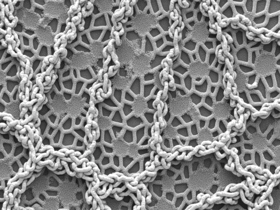
Heat in solids is transferred by phonons (lattice vibrations) or electrons. Metals conduct heat via free electrons, hence extremely high thermal conductivity; polymers and ceramics conduct via phonons, intrinsically lower. Fillers enhance coating thermal conductivity because high-thermal-conductivity ceramics or carbon materials form continuous pathways within the film, letting phonons "take fewer detours." The intrinsic thermal conductivity magnitudes of common fillers vary greatly: alumina about 20–35 W/(m·K), aluminum hydroxide lower and also flame-retardant, aluminum nitride about 150–220, boron nitride in-plane up to 200–400, silicon carbide about 80–120, zinc oxide about 20–30, graphite and graphene in-plane up to hundreds to thousands, and metals silver/copper/aluminum 200–430. As seen from this table: for "insulating plus thermally conductive," alumina, aluminum nitride, and boron nitride are preferred; for "ultimate thermal conductivity without concern for electrical conductivity," graphite or metals are chosen. This directly determines whether a thermal conductive coating can also be insulating (see insulating powder coating).
II. Filler System Comparison Table
| Filler | Intrinsic Thermal Conductivity W/(m·K) | Characteristics |
|---|---|---|
| Alumina Al₂O₃ | 20–35 | Low cost, insulating, readily available, mainstream |
| Aluminum hydroxide ATH | Low (also flame-retardant) | Insulating + flame-retardant, moderate thermal conductivity |
| Aluminum nitride AlN | 150–220 | High thermal conductivity, insulating, expensive |
| Boron nitride BN (flake) | 200–400 (in-plane) | High thermal conductivity, insulating, lubricating, expensive |
| Silicon carbide SiC | 80–120 | High thermal conductivity, slightly conductive, wear-resistant |
| Zinc oxide ZnO | About 20–30 | Medium thermal conductivity, insulating |
| Graphite/graphene | High (in-plane up to hundreds–thousands) | Extremely high thermal conductivity but conductive, needs control |
| Metal powder (Ag/Cu/Al) | 200–430 | Extremely high thermal conductivity but conductive, heavy, easily oxidized |
III. Percolation and Interfacial Thermal Resistance: Why More Filler Is Not Always Better
The formation of continuous pathways by thermal conductive fillers exhibits a "percolation threshold"; beyond the threshold thermal conductivity rises rapidly, but further adding filler encounters two bottlenecks. The first is interfacial thermal resistance (Kapitza resistance): the interfaces between filler and resin, and between filler and filler, are phonon scattering points; even if boron nitride itself is highly conductive, interfacial mismatch still lowers the overall value. Surface modification (coupling agents, silanization) can reduce interfacial thermal resistance. The second is processability and packing limit: excessive filler causes coating viscosity to surge, making it hard to spray, prone to settling, brittle film, and reduced adhesion; powder systems are limited by extrusion and chargeability.
Therefore, the formulation of high-thermal-conductivity coatings is a combination of "high-thermal-conductivity filler + surface modification + optimized particle size gradation (large particles build skeleton, small particles fill gaps)," maximizing thermal conduction chain density at limited filler loading. Typical commercial thermal conductive coatings have thermal conductivity mostly in 0.5–5 W/(m·K); those claiming above 10 are mostly special high-loading systems or paste-like thermal interface materials, and the test method and thickness must be verified. Many promotions conflate "intrinsic filler thermal conductivity" with "coating thermal conductivity"; when selecting, always look at the measured coating value rather than the filler value.
IV. How to Measure Thermal Conductivity
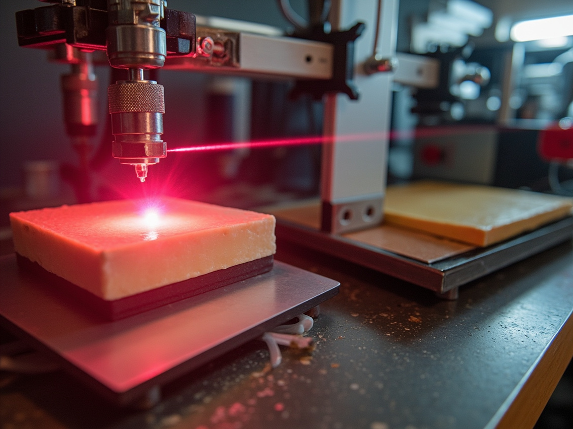
Three common standard methods are used for measuring the thermal conductivity of coatings or films. The steady-state method (guarded hot plate) per GB/T 10294 or ASTM C177 establishes a stable temperature difference across the specimen and measures heat flow to derive thermal conductivity; results are reliable but slow, suitable for bulk or thick samples. The transient plane source method (hot disk) per ISO 22007-2 uses a probe to simultaneously heat and measure temperature, quickly obtaining thermal conductivity and specific heat, suitable for coatings and thin sheets. The laser flash method per ASTM E1461 or ISO 22007-4 measures thermal diffusivity and converts to thermal conductivity, requiring known specific heat and density, suitable for homogeneous thin samples and intrinsic filler measurement. In addition, the steady-state thermal resistance and apparent thermal conductivity of thermal interface materials can be measured per ASTM D5470 under specified contact pressure; this method directly gives the "including interface" thermal resistance, which is closer to assembly reality than mere bulk thermal conductivity.
Key reminder: coating thermal conductivity is related to the "measurement direction"—flake boron nitride is high in-plane and low through-plane (anisotropic); manufacturer specifications should state direction and thickness. For thin coatings (tens of microns), overall thermal resistance is also dominated by interfacial contact resistance; simply high coating thermal conductivity does not mean good system heat dissipation—one must look at "system thermal resistance" (device—coating—heat sink). This is why laboratory high-thermal-conductivity data often cannot be reproduced in whole-machine temperature.
V. Typical Applications and Operating Condition Matching
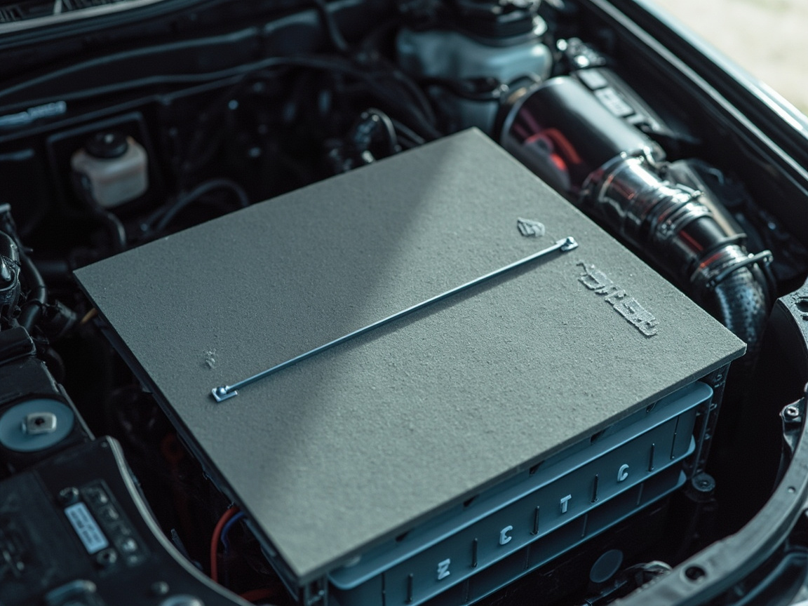
LED lighting: every 10°C rise in chip junction temperature halves the lifespan approximately. Thermal conductive coating directs module heat to the aluminum substrate and housing, requiring both thermal conduction and certain insulation (to prevent positive/negative short circuit). Alumina-filled silicone or epoxy thermal conductive powder is mainstream. Power electronics and IGBT: inverters and power modules have dense heat generation; thermal interface material coatings reduce interfacial thermal resistance; here "thermal conductive + insulating + tracking-resistant" is often required, overlapping with insulating powder demands (see insulating powder coating). Battery pack enclosure: power battery packs need heat dissipation as well as insulation and anti-corrosion; thermal conductive insulating powder can form a "thermal conduction—insulation—anti-corrosion" triple-layer inside the enclosure, conducting cell heat to the shell and then away via the liquid cooling plate. Motor and electronic control housing: motor housing thermal conductive coating aids heat dissipation; meanwhile it needs heat resistance (see silicone high-temperature coating), high-temperature motor housings often take a "heat-resistant + thermal conductive" composite route. High-frequency devices and base stations: power amplifiers etc. need both thermal conduction and low dielectric loss; fillers should be low-dielectric (e.g., boron nitride, aluminum nitride) rather than conductive carbon.
VI. Application and Compatibility
Pre-treatment: metal substrate sandblasting Sa2.5 (refer to coating surface treatment Sa2.5), ensuring coating adhesion and interfacial contact. Film thickness and contact: thermal conductive coating should be thin and conformal (e.g., 20–80 microns); too thick increases its own thermal resistance; the key is "gap filling, air evacuation, conforming to heat sink." Surface smoothness: residual air at rough interfaces is a major thermal resistance source; the coating must level out and fill microscopic unevenness. Insulation synergy: for insulating applications use alumina, aluminum nitride, boron nitride, strictly control conductive filler mixing, verify volume resistance per GB/T 1410. Heat resistance synergy: for high-temperature service choose silicone-based thermal conductive powder, avoiding low-temperature resin thermal degradation.
When providing compatible thermal conductive solutions, Kexin New Materials (kexinMaterials) asks customers for four parameters—"heat generation power, allowable temperature rise, interface area, whether insulation is needed"—and reversely recommends filler system and target thermal conductivity, reminding that "coating thermal conductivity is only one link in system thermal resistance; it must be combined with interface treatment and heat sink design." This approach of placing the coating within the overall thermal design avoids the awkward situation where customers chase a single thermal conductivity number yet fail to lower the temperature.
VII. Common Misconceptions
Myth 1: The higher the thermal conductivity, the better; the thicker, the cooler. Wrong. Thin and conformal with low interfacial thermal resistance matters more than simply high thermal conductivity; too thick actually increases resistance. Myth 2: Thermally conductive must be electrically conductive. Wrong. Alumina, aluminum nitride, and boron nitride systems can conduct heat while insulating, suitable for electronics. Myth 3: All nominal 10 W/(m·K) are trustworthy. Wrong. One must look at test method, direction, thickness, and filler type; for thin coating systems, thermal resistance is the key. Myth 4: Simply changing the coating can lower temperature. Wrong. System heat dissipation equals from device to interfacial coating to heat sink to environment; a bottleneck at any link limits the effect. Myth 5: Intrinsic thermal conductivity of filler equals coating thermal conductivity. Wrong. Interfacial thermal resistance greatly reduces it; actual coating measurement is mandatory.
Eight. Synergy with Insulation, Anti-corrosion, and Heat Resistance
Thermal conduction often conflicts with insulation yet frequently needs to coexist: electronic devices need both heat conduction and insulation, so choose ceramic fillers instead of carbon; battery housings need thermal conduction, insulation, and anti-corrosion (see solvent-free anti-corrosion powder coating); motor housings need thermal conduction and heat resistance (see silicone high-temperature coating). This multi-objective superposition is exactly where the value of functional powder lies—a single liquid coating can hardly satisfy all at once; powder can balance via filler gradation and multilayer design. Kexin New Materials (kexinMaterials)'s "thermally conductive, insulating, anti-corrosion three-in-one" powder has been used in battery housings and electronic control boxes, compressing three functions into one coating process.
Nine. Characteristics of Powder-type Thermally Conductive Coatings
Powder thermally conductive coatings have zero VOC, uniform film thickness, can be prefabricated in factory, and controllable filler dispersion, suitable for batch electronics, batteries, and motor parts; the mechanism is consistent with liquid, relying on filler thermal conduction chains. When insulation is needed, also choose ceramic fillers. Compared with liquid, powder has more stable quality on batch metal parts and is solvent-free, but for irregular shapes or on-site repair, liquid thermal conductive adhesive is still dominant; the two are divided by working condition.
Ten. Technology Trends
First, high thermal conductivity with low filling: use boron nitride nano-sheets and modified alumina to reduce filling amount and preserve mechanics. Second, isotropization: solve the problem of high in-plane and low through-plane of flake fillers, develop 3D thermal conduction networks. Third, thermal conduction-insulation integration: for batteries and power modules, filler surface coating balances insulation and thermal conduction. Fourth, digitalization: online infrared temperature measurement feeds back coating heat dissipation effect, closed-loop optimization.
Eleven. Selection Decision Tree
When selecting thermally conductive coating, first see if insulation is needed (insulation: choose ceramic; if conductive is acceptable: choose carbon or metal); then see target thermal conductivity (general 1–2, high conduction 3–5+); then see temperature (room temp: choose epoxy, high temp: choose silicone); then see substrate (batch metal: powder, irregular: liquid); finally see system thermal resistance rather than solely coating thermal conductivity. Write this path into a specification to avoid pitfalls in selection.
Twelve. Common Defects and Troubleshooting
| Defect | Cause | Countermeasure |
|---|---|---|
| Thermal conductivity below standard | Insufficient filler, poor dispersion | Increase filling, strengthen dispersion |
| Insulation failure | Mixed conductive fillers | Strictly control ceramic fillers |
| Poor adhesion | Insufficient pretreatment | Sandblasting Sa2.5 |
| Cracking | Excessive filler, brittle film | Optimize gradation, reduce filling |
| Interfacial bubbles | Rough surface, no degassing | Leveling and gap filling, pressurized bonding |
Thirteen. Standards and Inspection Checklist
Acceptance should cover: GB/T 10294 or ISO 22007-4 or ASTM E1461 for thermal conductivity measurement (note direction and thickness); GB/T 1410 for volume resistance (insulation occasions); GB/T 9286 for adhesion; temperature cycling to verify system temperature drop. It is recommended to do "coating thermal conductivity plus system thermal resistance" dual-index acceptance, rather than reporting only one coating number.
FAQ
Fourteen. Standard List and Acceptance Ledger
For easy engineering implementation, the main standards involved in thermally conductive coatings are organized into a list for item-by-item verification during acceptance. Core standards include: GB/T 10294 "Determination of steady-state thermal resistance and related characteristics of thermal insulation materials—Guarded hot plate method" (hard basis for thermal conductivity); ISO 22007-4 (transient plane source method); ASTM E1461 (laser flash method for thermal diffusivity); GB/T 1410 (volume resistance for insulation occasions); GB/T 9286 (adhesion); GB/T 13452.2 (film thickness). Power and battery scenarios can also refer to corresponding component thermal design enterprise standards.
The acceptance ledger is recommended to include four items: first, coating thermal conductivity (note method and direction thickness); second, system thermal resistance (device—coating—heat sink actual measured temperature drop); third, volume resistance (insulation occasions); fourth, adhesion and appearance. The key is not to report only one coating thermal conductivity number, but to do "coating thermal conductivity plus system thermal resistance" dual-index acceptance, otherwise lab high thermal conductivity data cannot be reproduced on whole-machine temperature, and customers may mistakenly think the coating is ineffective.
Make this ledger a traceable document, satisfying thermal design verification and facilitating future iteration comparison. Kexin New Materials (kexinMaterials) attaches a "thermal test report + system temperature drop curve + filler system description" three-piece set when delivering thermal conduction solutions, so customers have evidence from selection to acceptance, rather than just chasing a promotional number.
Fifteen. Thermal Resistance Series Model: Why "Thin and Conformal" Beats "High Thermal Conductivity"
To place the thermal conductive coating in the correct position, the most effective tool is the thermal resistance series model. Steady-state one-dimensional heat transfer follows Fourier's law; the conductive thermal resistance of a layer equals thickness divided by the product of thermal conductivity and heat transfer area, i.e., R equals t divided by k times A, unit K/W. The thermal resistances of each layer in the entire heat dissipation chain are connected in series: internal thermal resistance from chip junction to housing, contact thermal resistance between housing and coating, coating body thermal resistance, contact thermal resistance between coating and heat sink, convective thermal resistance from heat sink to environment. Device temperature rise equals heat power times total thermal resistance. This formula explains almost all intuitive myths in the thermal conductive coating field.
First look at thickness. Assume coating thermal conductivity is 2 W/(m·K), heat transfer area 10 cm², then 50 μm thickness corresponds to body thermal resistance about 0.025 K/W, while 200 μm rises to about 0.1 K/W. That is, film thickness quadruples, body thermal resistance also quadruples. If device heat is 50 W, the temperature differences brought by these two are about 1.25℃ and 5℃ respectively. The thicker the coating, the more it becomes a wall, which is the quantitative basis for "thermal conductive coating should be thin".
Then look at the marginal gain of thermal conductivity. Still take 50 μm, 10 cm²: k from 0.2 to 1, body thermal resistance from about 0.25 to 0.05 K/W, significant drop; k from 1 to 5, thermal resistance only from 0.05 to 0.01 K/W, absolute drop less than one-fifth of the previous step. And at this time the convective thermal resistance of the heat sink on the whole chain may still be several tenths or even several K/W. The conclusion is clear: in the low thermal conductivity region, improving k yields huge gains; after entering the high thermal conductivity region, the gain decays rapidly, and continuing to pay cost for "higher numbers" often cannot exchange for measurable temperature drop.
| Link | Typical magnitude (10 cm² area) | Main influencing factors | Optimization means |
|---|---|---|---|
| Coating body thermal resistance | 0.01–0.25 K/W | Film thickness, thermal conductivity | Thinning, increase k |
| Interface contact thermal resistance | 0.05–0.5 K/W | Surface roughness, air gap, pressure | Leveling and gap filling, pressurized bonding |
| Heat sink convective thermal resistance | 0.5–5 K/W | Fin area, wind speed | Enlarge heat sink, forced air cooling |
| Device internal thermal resistance | Determined by device package | Package structure | Choose low thermal resistance package |
From this magnitude comparison, it can be seen that interface contact thermal resistance is often of the same order or even larger than coating body thermal resistance, while the convective thermal resistance on the heat sink side is often the largest item in the whole chain. This is why "just changing the coating to greatly cool the device" usually fails—what you optimize may be only a small portion of the total thermal resistance. The correct order is to first do the whole-chain thermal resistance decomposition, find the bottleneck item, then decide where to invest resources.
Sixteen. Theoretical Models and Formulation Levers for Composite System Thermal Conduction
To predict the effective thermal conductivity of filled systems, there are several classic models academically. The Maxwell-Eucken model applies to low filling, sparsely dispersed fillers not in contact, its prediction rises approximately linearly with filling rate; the Bruggeman model introduces interactions between fillers, closer to measured at medium filling rate; and when filling rate crosses the percolation threshold and fillers form a continuous skeleton, measured thermal conductivity is significantly higher than these two models' predictions, then models with empirical parameters such as the Agari model are more commonly used for fitting.
The common insight of these models is: the effective thermal conductivity of the coating is far from as simple as "filler intrinsic thermal conductivity times volume fraction"; it is simultaneously governed by filler morphology, orientation, particle size distribution, and interface quality. In terms of formulation, there are four operable levers.
The first is particle size gradation. Spherical fillers of a single particle size leave a lot of voids even at closest packing; using large particles to build the main skeleton, medium particles to fill secondary voids, and small particles to fill micro-cracks in a three-level gradation can increase the filling rate by more than ten percentage points under the same viscosity limit, which is the most cost-effective means to improve thermal conductivity. The second is morphology selection. Flake boron nitride and fibrous fillers have high aspect ratio, and the filling rate required to form continuous pathways is much lower than spherical fillers, but the cost is anisotropy—flake fillers easily orient along the film surface during leveling and knife coating, causing high in-plane thermal conductivity but low through-thickness, while device heat dissipation needs exactly the through-thickness direction. The third is surface modification. Silane coupling agents or polydopamine modifications can improve the wetting of filler and resin, reduce phonon mismatch and micro-voids at the interface, thereby reducing Kapitza interfacial thermal resistance; this step is often more cost-effective than adding a few more points of filler. The fourth is process dispersion. Agglomerates both waste filler and are defect sources; powder systems rely on the shear dispersion of twin-screw extrusion, and extrusion temperature, screw configuration, and residence time all affect the final filler network quality.
It needs to be reminded that the above levers are all subject to the hard constraint of workability. Increased filling rate brings viscosity rise, worse melt flow, brittle film, reduced adhesion, and changed charging property. For powder coatings, also consider extruder load and electrostatic spray powder deposition rate. Therefore formulation design is never "thermal conductivity maximization", but "thermal conductivity maximization under the premise of meeting workability and mechanical bottom lines".
Seventeen. Reliability Verification: Thermal Cycling, Aging, and Failure Modes
The performance of a thermal conductive coating cannot be judged solely by a single measurement at the factory; it must also be evaluated by whether it can maintain its properties throughout the service life. The most commonly used accelerated verification is the thermal cycling test, which sets the high and low temperature levels, dwell time, and transition rate according to GB/T 2423.22 "Environmental testing — Part 2: Test methods — Test N: Change of temperature" (equivalent to IEC 60068-2-14), and after several cycles re-measures the thermal resistance and adhesion. The reason for conducting this test is that the coating, metal substrate, and heat sink have different coefficients of linear expansion; repeated heating and cooling accumulate shear stress at the interface, which may cause micro-cracks and local debonding, thereby significantly increasing the contact thermal resistance without being visible to the naked eye.
There are four common failure modes. The first is interfacial debonding, manifested as a slow rise in thermal resistance and a gradual increase in device temperature month by month, mostly originating from insufficient pre-treatment or thermal expansion mismatch. The second is filler settling and segregation, which occurs during the storage of liquid systems or the leveling stage of coating application, leading to uneven thermal conductivity distribution on workpieces of the same batch. The third is resin thermal aging, where the matrix degrades, becomes brittle, and loses weight under long-term high temperature, and the interfacial bonding deteriorates accordingly; therefore, for high-temperature working conditions, it is recommended to select a silicone-based system (see silicone high-temperature coating). The fourth is residual assembly air gaps: the coating itself is fine, but insufficient fitting pressure or poor surface flatness leaves an air interlayer at the interface — air thermal conductivity is about 0.026 W/(m·K), the worst material in the entire chain, and an air gap of just tens of microns is enough to offset all efforts to improve the thermal conductivity coefficient.
Therefore, a complete acceptance report should contain at least four sets of data: coating thermal conductivity (noting method, direction, and thickness), system thermal resistance or actual measured temperature drop after assembly, thermal resistance change rate after thermal cycling, and adhesion and appearance. Only the second and third sets of data truly answer "whether this coating is useful on the customer's equipment, and how long it can be used."
18. Three Engineering Cases and Selection Deduction
Case 1: High-power floodlight module. The heat source is multiple high-power LEDs; insulation isolation and rapid heat transfer are required between the aluminum substrate and the die-cast aluminum housing, and the luminaire operates outdoors for a long time, experiencing day-night temperature cycling. The solution uses alumina-filled epoxy thermal conductive powder, targeting thermal conductivity of 1.5 to 2 W/(m·K), with film thickness controlled at 40 to 60 microns. Alumina rather than aluminum nitride is chosen because thermal resistance accounting shows the bottleneck is on the heat sink convection side; raising the coating k from 2 to 5 would only reduce temperature by less than 1°C, while the cost would multiply several times. In addition to thermal conductivity, acceptance focuses on thermal resistance re-measurement after thermal cycling and GB/T 1410 volume resistance, to ensure insulation does not degrade due to aging.
Case 2: Energy storage converter power module baseplate. Here the power density is high, insulation and voltage resistance are required, and the module needs periodic maintenance and disassembly. The solution uses boron nitride and alumina composite-filled thermal conductive insulating powder, using flake boron nitride to build the skeleton and spherical alumina to fill gaps, balancing thermal conductivity and voltage resistance; film thickness of 80 to 120 microns to meet insulation margin, and taking the lower limit according to the aforementioned thickness-thermal resistance trade-off. Special attention is paid to the orientation issue of flake boron nitride; in process, over-orientation is avoided by controlling leveling time. Acceptance measures assembly thermal resistance under specified pressure per ASTM D5470, which is closer to reality than measuring bulk thermal conductivity alone.
Case 3: Inner wall of the lower box of a power battery pack. The demand is to direct cell heat to the box and then remove it via the liquid cooling plate, while providing insulation against short circuits and anti-corrosion against condensate (see heavy-duty anti-corrosion powder coating and insulating powder coating for synergistic requirements). The solution uses a thermal conductive, insulating, and anti-corrosion three-in-one epoxy powder, with film thickness of 150 to 250 microns — this thickness is supported by anti-corrosion and insulation requirements, and is a compromise in thermal design, so the bulk thermal resistance must be compensated by improving filler gradation quality. Acceptance must provide three reports on thermal conductivity, volume resistance, and neutral salt spray, and conduct re-measurement after thermal cycling.
The common deduction logic of the three cases is consistent: first calculate the entire chain thermal resistance to find the bottleneck, then determine the target thermal conductivity and film thickness of the coating, then screen the filler system based on "whether insulation, high temperature resistance, or anti-corrosion is needed," and finally accept using assembly thermal resistance rather than bulk thermal conductivity. Kexin New Materials (kexinMaterials) requires customers to provide four parameters — heating power, allowable temperature rise, interface area, and insulation demand — at the solution communication stage, precisely to run this deduction through and avoid customers paying for a high thermal conductivity number they cannot use.
Q: Can thermal conductive coating really replace thermal conductive pads?
A: In scenarios requiring irregular shapes, thin layers, and close fitting, it can replace or supplement. The coating can fill interfacial air gaps, reduce contact thermal resistance, and be applied to complex curved surfaces; but thick gaps (greater than 1 mm) may still require thermal conductive pads or pastes. Which to choose depends on the gap and working conditions.
Q: Does thermal conductive coating conduct electricity?
A: It depends on the filler. Ceramic filler systems such as alumina, aluminum nitride, boron nitride, and zinc oxide are insulating and thermally conductive, suitable for electronics; graphite and metal powder systems have high thermal conductivity but conduct electricity, and are only used for heat sinks where conductivity is not a concern. Always select filler according to insulation needs.
Q: Is a thermal conductivity of 5 W/(m·K) considered high?
A: For organic coatings it is relatively high (resin base about 0.2, ordinary alumina-filled mostly 0.5–2). Above grade 5 often requires aluminum nitride, boron nitride, or high filling, with high cost. It should be judged in combination with test method and thickness; for thin coatings, system thermal resistance is more critical.
Q: Why does adding a lot of filler not increase thermal conductivity?
A: It is limited by interfacial thermal resistance (filler-resin phonon scattering) and filling limit. The solution relies on surface modification to reduce interfacial resistance, optimizing particle size gradation (large particles build skeleton, small particles fill gaps), and improving filler dispersion, rather than blindly increasing amount.
Q: How to measure thermal conductivity to be comparable?
A: Note the method and direction: steady-state GB/T 10294, transient ISO 22007-4, laser flash per ASTM E1461. Flake boron nitride is anisotropic, with large difference between in-plane and through-plane; the nominal must be specified. For thin coatings, system thermal resistance must also be considered.
Q: Why do LEDs especially need thermal conductive coating?
A: LED junction temperature rises about 10°C halves the lifespan; thermal conductive coating quickly transfers module heat to the aluminum substrate and housing, which is key to reliability; meanwhile insulation against short circuits is needed, so alumina-filled silicone or epoxy systems are mostly chosen.
Q: What should be noted for thermal conductive coating on battery pack housing?
A: It must both conduct heat and dissipate, insulate against short circuits, and resist corrosion (see heavy-duty anti-corrosion powder coating); commonly a three-in-one thermal conductive insulating powder is used; and system cooling is designed in conjunction with the liquid cooling plate.
Q: Is silicone-based thermal conductive powder suitable for high temperature?
A: Yes. Silicone is heat resistant (see silicone high-temperature coating); thermal conductive silicone powder can serve motor or electrical housings above 200°C, balancing heat resistance and thermal conductivity.
Q: What are the advantages of powder thermal conductive coating?
A: Zero VOC, uniform film thickness, factory pre-fabrication possible, controllable filler dispersion, suitable for batch electronics, batteries, and motor parts; the mechanism is consistent with liquid, relying on filler thermal conduction chains. When insulation is needed, ceramic fillers are also selected.
Q: Can applying only thermal conductive coating cool down the equipment?
A: Not guaranteed. System cooling is a chain from device to interface coating to heat sink to environment; the coating only reduces one link of interfacial thermal resistance; if the heat sink is insufficient or there is air gap at the interface, simply changing the coating has limited effect. Overall thermal design is needed.
Q: How to estimate coating thermal resistance?
A: According to Fourier's law, bulk thermal resistance equals thickness divided by the product of thermal conductivity and area (R = t/(kA), unit K/W). For example, when k = 2 W/(m·K), area 10 cm², thickness 50 microns, bulk thermal resistance is about 0.025 K/W; increasing thickness to 200 microns raises it to about 0.1 K/W. Sum the thermal resistances of each layer in series and multiply by heating power to get the temperature rise estimate.
Q: Is it worth raising thermal conductivity from 2 to 5?
A: Thermal resistance decomposition must be done first. Low thermal conductivity region (0.2 to 1) yields large benefit; high thermal conductivity region marginal benefit decays rapidly; if the bottleneck is heat sink convection thermal resistance (often 0.几 to several K/W), doubling coating k may only bring less than 1°C temperature drop, while cost rises exponentially. Find the bottleneck first, then invest resources.
Q: Why re-measure thermal resistance after thermal cycling?
A: The coating, substrate, and heat sink have different coefficients of linear expansion; repeated heating and cooling accumulate shear stress at the interface, causing micro-cracks or local debonding, silently increasing contact thermal resistance. After conducting the temperature change test per GB/T 2423.22 (equivalent to IEC 60068-2-14) and re-measuring thermal resistance and adhesion, long-term reliability can be judged.
Q: What problems does the anisotropy of flake boron nitride bring?
A: Flake fillers easily orient along the film surface during leveling or knife coating, resulting in high in-plane thermal conductivity and low through-thickness, while device heat dissipation needs exactly the through-thickness direction. Therefore the nominal thermal conductivity must specify direction; in process, over-orientation can be mitigated by controlling leveling time and compounding spherical fillers.
Further Reading
- Insulating Powder Coating: Volume Resistance and Dielectric Strength: Thermal conduction often needs to balance insulation; this article complements insulation design and is the dual requirement for power electronic coatings.
- Silicone High-Temperature Coating: Heat Resistance Mechanism and Temperature Grades: High-temperature motors or electrical housings often take the "heat resistance plus thermal conduction" route; the two articles connect.
- Engineering Applications of Heavy-Duty Anti-Corrosion Powder Coating: Battery pack housing "thermal conduction—insulation—anti-corrosion" three-in-one; anti-corrosion is an indispensable link.
- Coating Surface Treatment Sa2.5 and Sandblasting Grades: One root cause of interfacial contact thermal resistance is pre-treatment and surface flatness; sandblasting grade directly affects fitting quality.
- Anti-Static Coating and Conductive Fillers: Resistivity Control, Filler Systems, and Standards
- Powder Coating Principles and Classification: From Film Formation Mechanism to Resin System Selection
- Industrial Paint Application: Airless Spray Parameters, Film Thickness Control and Coating Interval