Nano coating: "70% lies in the process, 30% in the formulation". With the same set of nano-modified resin, if surface treatment is inadequate, dispersion is uneven, or the curing window is out of control, performance may be halved or even fail. Compared with conventional coatings, nano coatings are more sensitive to substrate cleanliness, nano dispersion, film thickness uniformity, and degree of cure. This article systematically reviews the full application process: surface treatment → nano dispersion/liquid preparation → application method (spraying/dip coating/spin coating/CVD/PVD/sol-gel) → curing → quality control. All quantitative requirements correspond to real standards such as ISO 8501-1, GB/T 8923, GB/T 9286, GB/T 13452, with no fabricated numbers.
Kexin New Materials (kexinMaterials) generally adopts a bundled approach of "product + process card + inspection template" when delivering nano-modified industrial protective and functional coatings, writing process boundaries into the SOP. This article also incorporates application key points from its publicly available technical materials to help customers convert "master's feel" into reproducible data.
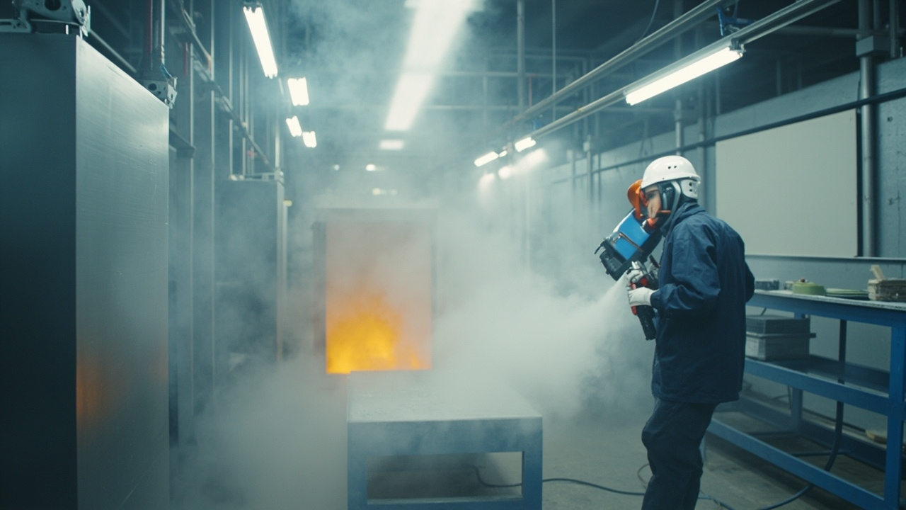
I. Surface Treatment: The Foundation of All Adhesion
Regardless of whether the substrate is steel, aluminum, plastic, or PCB, the first step of construction is to "make the surface reliably adherent":
- Sandblasting/shot blasting (metal): According to ISO 8501-1 / GB/T 8923.1, the commonly used grade is Sa 2½ (near-white blast cleaning), with surface roughness Ry5 ≈ 40–75 µm (depending on the system). For marine and heavy anti-corrosion, soluble salts (ISO 8502 series, Bresle method) have separate upper limits; exceeding the limit will inevitably cause flash rust (see nano marine anti-rust).
- Degreasing/oil removal: Solvent wipe, alkaline wash, or plasma cleaning to remove wax, silicone oil, and oil stains, aiming for uniform surface energy and wettability.
- Plastic/electronic substrates: Often require plasma/corona activation to increase surface energy and improve wetting of low-surface-energy materials (see nano coating wettability and contact angle).
- Sanding/scuffing: When recoating old paint beyond the window, sanding is needed to enhance adhesion.
Key principle: The upper limit of adhesion (GB/T 9286 cross-cut 0/1 grade is excellent, or GB/T 5210 pull-off method in MPa) is determined by surface treatment; no matter how good the nano formulation is, it cannot save a dirty substrate.
1.1 Cleanliness Grades: The Exact Meaning of Sa and St
ISO 8501-1:2007 / GB/T 8923.1-2011 uses photographic standards to grade visual cleanliness; engineering quotations and acceptance are based on this terminology:
| Grade | Treatment method | Visual criteria (per ISO 8501-1) | Common application |
|---|---|---|---|
| Sa 1 | Blast cleaning | Light cleaning, removal of loose mill scale, rust, and contaminants | Temporary protection, low grade |
| Sa 2 | Blast cleaning | Thorough cleaning, residues firmly adherent and limited in distribution | C2–C3 general environment |
| Sa 2½ | Blast cleaning | Very thorough (near-white), only slight specks/streak shadows allowed | C4–C5, mainstream for nano-modified heavy anti-corrosion |
| Sa 3 | Blast cleaning | Visually clean (white grade), uniform metallic color | Immersion, chemical media, special systems |
| St 2 / St 3 | Hand/power tool | Thorough / very thorough hand derusting | Touch-up, sites where blasting is impossible |
The reason nano-modified primers generally specify Sa 2½ rather than Sa 2 is that nano fillers make the coating's barrier path more "dense"; once hidden rust under residual mill scale remains on the substrate, defect locations will form concentrated electrochemical cells under the film, amplifying pitting. In other words, the denser the coating, the more sensitive it is to substrate defects.
1.2 Roughness: Not the Rougher the Better
Roughness provides mechanical interlocking, but excessive roughness leads to "peak through" — the actual film thickness at the tops of convex peaks is far lower than the average dry film thickness, becoming the earliest rust spots.
- ISO 8503-1/-2 uses comparison specimens to classify roughness into fine, medium, and coarse, and distinguishes steel shot (S, round abrasive, forming valley-type morphology) from steel grit (G, angular abrasive, forming peak-type morphology).
- ISO 8503-4 gives Ry5 values by stylus method, ISO 8503-5 is the replica tape method, suitable for on-site evidence.
- Engineering rule of thumb: Ry5 generally should not exceed 1/3 of the primer dry film thickness, and the abrasive particle size must match the target roughness; under the same target roughness, steel grit more easily obtains angular morphology and higher specific surface area than steel shot.
1.3 Soluble Salts, Dust, and Dew Point: Three On-site "Invisible Penalties"
These three items are often overlooked in quotations but are the main source of rework:
- Soluble salts: ISO 8502-6 (Bresle patch sampling) + ISO 8502-9 (field conductivity method) give NaCl equivalent (mg/m²). Offshore specs such as NORSOK M-501 require soluble salts on blasted surface not to exceed the order of 20 mg/m²; specific limits are subject to owner specifications. Salts are the root cause of osmotic blistering, cannot be removed by blasting, and must be washed with high-pressure fresh water.
- Dust: ISO 8502-3 uses transparent tape imprint evaluated by "quantity grade 0–5" and "size grade 1–5"; most engineering specs require quantity grade no higher than grade 2. Floating dust after blasting becomes a debonding interlayer between coating and substrate.
- Dew point: ISO 8502-4 gives condensation probability assessment method; ISO 12944-7 and most product TDS require substrate temperature at least 3℃ above dew point. Winter and night construction, where steel plate temperature lags behind air temperature, are the most error-prone periods.
1.4 Differences in Pretreatment Process Cards for Different Substrates
| Substrate | Main treatment | Key control points | Common mistakes |
|---|---|---|---|
| Carbon steel | Blast cleaning Sa 2½, Ry5 medium | Salts, dust, dew point, coat within 4 h | Direct coating despite overnight flash rust |
| Hot-dip galvanized | Sweep blasting (low pressure) or alkaline wash + phosphating | Do not penetrate zinc layer, remove white rust | Use Sa 2½ parameters to thin zinc layer |
| Aluminum alloy | Degreasing + chemical conversion/anodizing | Avoid free chloride ion residue | Cross contamination with carbon steel abrasive |
| Stainless steel | Non-ferrous abrasive sweep blasting or pickling passivation | Strictly forbid ferrous abrasive (pitting risk) | Mixed use of steel grit causing rust spots |
| Engineering plastic | Plasma/corona activation | Surface energy meets standard (dyne pen or contact angle) | Activation expires after prolonged placement |
| Glass/ceramic | Alkaline wash + deionized water + silane primer | Surface hydroxyl density, dryness | Water mark residue causing spotting |
| PCB | Ultrasonic board washing + ion contamination test | Flux residue (IPC-TM-650 2.3.25) | Coating directly without washing, sealing ions |
Activation-type pretreatments (plasma, corona, flame) have a clear "time validity": surface energy declines with placement time. Industrial practice usually requires coating within tens of minutes to several hours after activation; the specific window must be determined by process validation and written into the process card.
II. Nano Dispersion and Liquid Preparation: Anti-aggregation is the Core
Nano fillers (SiO₂, Al₂O₃, TiO₂, Zn, etc.) have huge specific surface area and are extremely prone to agglomeration. Before construction, it is necessary to:
- Surface modification: Wrap with silane coupling agent and dispersant to reduce surface energy and improve compatibility with resin.
- High-speed dispersion + bead milling: Break agglomerates to primary particle size; monitor particle size distribution by laser diffraction (DLS) or TEM.
- Maturation/defoaming: Two-component or sol-gel systems need maturation after mixing to homogenize precursor hydrolysis-condensation and remove bubbles.
- Viscosity control: Adjust to corresponding viscosity according to application method (thin for spraying, medium for dip coating, thick for brushing); temperature affects viscosity and must be constant.
Consequences of poor dispersion: nano particles become "defect sources", shielding/toughening/hydrophobicity all compromised, even gun clogging and orange peel. This is the biggest invisible threshold distinguishing nano construction from ordinary coatings.
2.1 Three Stages of Dispersion: Wetting — Deagglomeration — Stabilization
Industrial dispersion is not "just stirring", but a series of three physical processes in sequence; missing any step will cause re-agglomeration after standing for several days:
- Wetting: The resin/solvent must first displace the air and water film adsorbed on the surface of the nanoparticles. If the surface tension of the liquid phase is higher than the critical surface tension of the particles, wetting cannot proceed spontaneously and a wetting agent must be used to lower the interfacial tension.
- Deagglomeration: Mechanical shear is used to break soft agglomerates back to near primary particle size. The high-speed disperser disk provides only "pre-dispersion"; true deagglomeration relies on the shear and impact between zirconia beads in a bead mill (sand mill).
- Stabilization: Once deagglomerated, particles without steric or electrostatic barriers will re-aggregate due to van der Waals attraction. The chemically grafted layer formed by silane coupling agent and the steric layer formed by polymeric dispersant are the key to "locking in" the deagglomeration results.
The chemical process of silane coupling agent can be written in two steps: the general formula R—Si(OR′)₃ first hydrolyzes to form silanol R—Si(OH)₃, which then condenses with surface hydroxyl groups of nanoparticles to form Si—O—Si covalent bonds; the organic functional group at the other end of the molecule (epoxy, amino, vinyl, methacryloxy, etc.) participates in curing crosslinking with the base resin, thereby upgrading "physical blending" to "chemical bonding". This is also why, with the same 3% nano SiO₂, the performance gap between modified and unmodified can be orders of magnitude.
2.2 Whether dispersion is qualified: four measurable criteria
| Criterion | Method / Instrument | Engineering meaning | Common reference | ||
|---|---|---|---|---|---|
| Scrape fineness | Scrape fineness gauge (GB/T 1724 / ISO 1524) | Fastest production-line criterion, to check for coarse particles | Nano systems should show no visible particle streaks to the naked eye | ||
| Particle size distribution | Dynamic light scattering DLS (ISO 22412) | D50 and polydispersity index PDI | Smaller PDI means narrower distribution; empirically <0.2 is a narrow distribution | ||
| Zeta potential | Electrophoretic light scattering | Electrostatic stability | Empirical criterion | ζ | > 30 mV is considered electrostatically stable |
| Morphology and primary particle size | TEM / SEM | Whether truly nano-scale, whether hard agglomerates exist | Corroborated with BET specific surface (GB/T 19587) |
It is necessary to distinguish "soft agglomerate" from "hard agglomerate": the former is formed by van der Waals forces and can be broken up by shear; the latter forms sintering necks during the powder calcination stage and cannot be solved by mechanical shear—only by changing the raw material. For powders that cannot be dispersed, do not use longer bead milling time to force it—excessive bead milling will wear the zirconia beads, introduce impurities, and raise temperature to damage the resin.
2.3 Liquid preparation and pot life: write the "chemical countdown" into the process card
- Viscosity and temperature: Most systems are highly sensitive to temperature; the flow cup reading (ISO 2431 / GB/T 1723) of the same formulation in winter and summer may differ by a factor of two. A qualified process card should state "adjust to X seconds at 23±2℃", not "thin it a bit".
- Pot Life: The pot life of multi-component systems can be evaluated according to ISO 9514 "Paints and varnishes — Determination of pot-life of multicomponent coating systems". Note that pot life shortens significantly with rising temperature; in summer the single batch size must be reduced.
- Induction Time: Some epoxy and polyurethane systems require standing for several minutes to over ten minutes after mixing before application, to allow pre-reaction to complete and bubbles to escape; this is a different concept from pot life and must not be confused.
- sol-gel aging: Precursor hydrolysis and condensation require time and water content control; the ambient humidity of the preparation environment directly affects the condensation rate, so temperature and humidity must be recorded.

Three. Coating methods: selection by precision and output
| Method | Application | Film thickness feature | Key points |
|---|---|---|---|
| Air / HVLP spray | Large-area steel structures, automotive | Tens to hundreds of µm | Atomization pressure, film thickness (GB/T 13452.2) controlled evenly |
| Airless spray | Heavy anti-corrosion thick coating | High DFT | High pressure, less overspray |
| Dip coating | Small parts, PCB, fasteners | Uniform but sagging risk | Pull-up speed controls thickness |
| Spin coating | Wafer / optical flats | Sub-micron extreme uniformity | Speed determines thickness, flat only |
| Selective coating | Electronics conformal protection | Local precision | Mask connectors / holes (see Electronic nano protection) |
| Vapor deposition (PVD/CVD) | Hard / DLC / like | Micron-level no dead angle | Vacuum, temperature, internal stress management |
| Sol-gel | Ceramic coating / glass | Sub-micron to several µm | Hydrolysis condensation, wipe window |
Automotive ceramic coating mostly uses "manual block coating + wiping" (sol-gel route), see Automotive ceramic hydrophobic mechanism; hard tool coatings go PVD/CVD; PCB conformal protection goes dip / selective spray. Selection is jointly determined by "substrate shape + film thickness + output + precision".
3.1 Spraying: translate "feel" into parameters
Spraying is the most mainstream method for nano-modified liquid coatings; reproducibility depends on whether four parameters are fixed in writing:
| Parameter | Air spray / HVLP | Airless spray | Defect affected |
|---|---|---|---|
| Atomization pressure | HVLP by definition air cap pressure not exceeding about 0.7 bar (10 psi) | Determined by pump pressure ratio, no compressed air atomization | Low pressure → orange peel; high pressure → dry spray, overspray |
| Pump pressure / nozzle | — | High-pressure pump with 0.4–0.8 mm class nozzle (per equipment TDS) | Nozzle too large → sagging; too small → streaking |
| Gun distance | About 15–25 cm (per TDS and fan pattern) | About 30–40 cm | Too close → sagging; too far → dry spray, poor adhesion |
| Gun travel speed and overlap | Constant speed, about 50% overlap | Same as left | Insufficient overlap → zebra stripes, uneven film thickness |
The core value of HVLP (high volume low pressure) is high transfer efficiency, less overspray, which is especially economical for formulations containing valuable nano fillers; airless spray is suitable for large-area high-solid thick slurry, high efficiency but atomization fineness inferior to air spray, use with caution for decorative topcoats. Materials containing hard nano fillers (Al₂O₃, SiC) should also pay attention to wear of pump and nozzle—worn nozzles will deform the fan pattern, a common hidden cause of "batch film thickness suddenly unstable".
3.2 Dip coating and spin coating: use physical laws to set thickness
- Dip coating in the low capillary number regime follows the Landau–Levich law: wet film thickness grows with about the 2/3 power of pull-up speed, and is positively correlated with viscosity and negatively correlated with surface tension. Engineering therefore uses "pull-up speed + temperature-controlled viscosity" as two knobs to set thickness, rather than relying on multiple dips.
- Spin coating: the classic Emslie–Bonner–Peck / Meyerhofer model gives film thickness approximately proportional to the −1/2 power of rotation speed (i.e., quadruple speed, thickness roughly halved), and is affected by solvent evaporation rate. It achieves sub-micron extreme uniformity but only applies to flat circular wafers; edge bead needs separate handling.
- The common premise of both is stable liquid viscosity, so spin/dip lines are generally equipped with constant temperature baths—a point often overlooked by teams transferring from spray lines.
3.3 Vapor deposition and sol-gel: temperature window determines substrate feasibility
- PVD (magnetron sputtering, arc ion plating): target atoms deposit in vacuum, process temperature typically in the hundreds of degrees Celsius range, depending on equipment and coating type; DLC class can be relatively low temperature, convenient for treating quenched tool steel without tempering. Film thickness mostly micron-level, internal stress management is the key to success.
- CVD hard coatings (TiN/TiCN/Al₂O₃): thermal CVD temperature can reach 800–1050℃ range, only suitable for cemented carbide and other high-temperature-resistant substrates; high-speed steel and steel parts are generally not applicable.
- sol-gel: Condenses at room or medium temperature, can treat heat-sensitive substrates such as glass, ceramics, and topcoat surfaces, but is extremely sensitive to ambient humidity and wiping timing (open time); it is the process with the strongest "human–material–environment" coupling.
One-sentence selection logic: First, whether the substrate tolerates heat cuts half the options; then check whether the shape can enter the vacuum chamber or be spun; only then talk about cost and throughput.
IV. Curing: Temperature, Humidity, and Windows
Curing determines the degree of crosslinking completeness and is the final switch for performance:
- Ambient-temperature curing (two-component/oxidation): Greatly affected by temperature and humidity; substrate temperature must be at least 3°C above dew point (ISO 12944-7), RH per TDS (commonly ≤ 70–85%). Pot Life is a hard deadline—exceeding it causes gelling and scrap.
- Heat/bake curing: Ranges from 60–200°C, significantly accelerating and improving crosslinking completeness (e.g., epoxy 60–80°C, silicone post-cure around 200°C). Panel temperature must be controlled to prevent degradation (see Thermal shock resistance of nano coating).
- UV curing: Photo-initiated instantaneous curing, suitable for flat high-speed lines, but shadowed areas do not cure.
- sol-gel ambient condensation: Ceramic coating crystallization relies on slow environmental moisture condensation, requiring water-free curing for 12–24 h, with full cure up to 7 days.
Regardless of type, the application card must specify "temperature range, humidity上限, film thickness target, recoat window, full cure period", otherwise batch variation is inevitable.
4.1 Surface dry, hard dry, and full cure: three time points that must not be confused
The most common phrase in engineering disputes is "it felt dry when I touched it yesterday." But a coating has three distinctly different time nodes:
| Node | Criterion | What is allowed | What is not allowed |
|---|---|---|---|
| Surface dry | Touch method/cotton ball method (GB/T 1728) | Dust prevention, low-speed ventilation | No loading, no recoating |
| Hard dry | Indentation/thick-layer drying method (GB/T 1728) | Light handling, most systems can be recoated | No water immersion, no chemical exposure |
| Full cure | Crosslinking degree/chemical resistance meets standard | Put into designed service condition | — |
Determining "full cure" cannot rely on a timetable, but on crosslinking evidence:
- DSC residual exotherm method: Measure the ratio of residual curing exothermic enthalpy to initial exothermic enthalpy to estimate cure degree; also check whether glass transition temperature Tg has reached plateau value.
- Solvent rub method (ASTM D5402): Use MEK double-rub count to assess solvent resistance; the most practical field indirect criterion (for solvent-sensitive systems).
- Hardness development curve: Whether pencil hardness (GB/T 6739) or pendulum damping (GB/T 1730) climb over time has flattened.
4.2 Recoat window: both minimum and maximum are hard deadlines
Multi-coat systems have two window lines: minimum recoat interval ensures the lower layer has load-bearing capacity and will not be lifted by the upper layer's solvent; maximum recoat interval ensures the lower layer surface still has enough active groups for interlayer chemical bonding. Exceeding the maximum recoat interval (especially obvious for epoxies, where surface becomes "whitened and slippery" due to amine bleed-out) requires abrading or washing before recoating, otherwise interlayer adhesion drops significantly—such delamination typically shows as clean interlayer peeling rather than substrate peeling in cross-cut test (GB/T 9286), and is easy to identify. ISO 12944-7 also lists recoat interval records as construction supervision content.
4.3 UV curing: dose, not time
UV curing lines must be controlled by dual parameters of irradiance (mW/cm²) + cumulative dose (mJ/cm²), and recorded by band (UVA/UVB/UVC/UVV), because different photoinitiators absorb different bands. Lamps decay with usage hours; scheduling only by "conveyor speed" will inevitably cause batch differences. Nano-modified UV systems also note: high-refractive-index or strongly absorbing nano fillers (e.g., TiO₂) block UV, causing insufficient deep curing; reduce addition or switch to low-absorption fillers (e.g., nano SiO₂).

V. Quality Control: Turning Process into Data
Delivery quality relies on quantitative checks; recommend writing into acceptance sheet:
- Film thickness: Wet film measured instantly, dry film sampled; magnetic/eddy-current thickness gauge (ISO 2808 / GB/T 13452.2).
- Adhesion: Cross-cut (GB/T 9286) grade 0/1 excellent, or pull-off (GB/T 5210) MPa.
- Appearance: No orange peel, sagging, particles, craters (low-surface-energy coatings prone to craters, need primer/activation).
- Functional indicators: Hydrophobicity by contact angle (GB/T 30693 / ISO 19403), abrasion by Taber (ASTM D4060), corrosion by salt spray (GB/T 1771).
- Environmental records: Temperature/humidity, dew point difference, surface preparation grade archived.
As a system supplier, Kexin New Materials (kexinMaterials) emphasizes "retain samples per batch + process parameter traceability", turning nano coating from art into engineering—this is the key to reducing complaints and stabilizing delivery.
5.1 Acceptance rule for dry film thickness: 80/20 principle
Film thickness is not "one point measured and qualified is enough." ISO 19840 "Paints and varnishes — Corrosion protection of steel structures by protective paint systems — Measurement and acceptance of dry film thickness on rough surfaces" gives the industry-common judgment framework: a single measured value generally not lower than 80% of nominal dry film thickness, average not lower than nominal dry film thickness, and specifies number of measurement points by area. Rough surfaces also need deduction of systematic deviation from roughness (per ISO 19840 correction value provisions).
For nano functional coatings, both too thin and too thick are harmful:
- Too thin: Insufficient barrier path, discontinuous hydrophobic layer, wear layer worn through;
- Too thick: Solvent entrapment causing pinholes and blistering, increased internal stress and shrinkage, sol-gel system surface skins while interior uncondensed, UV system deep layer uncured.
5.2 Overview of QC points, standards, and frequency
| QC point | Standard | Suggested frequency | Acceptance criterion (example, per project spec) |
|---|---|---|---|
| Surface cleanliness | ISO 8501-1 / GB/T 8923.1 | Per workpiece/per shift | Reach specified Sa grade |
| Roughness | ISO 8503-2/-4/-5 | Per shift or when changing abrasive | Within specified band |
| Soluble salts | ISO 8502-6 + ISO 8502-9 | Critical conditions per workpiece | Not exceed spec limit |
| Dust grade | ISO 8502-3 | Before coating | Quantity grade not higher than spec |
| Ambient temp/humidity/dew point | ISO 8502-4 / ISO 12944-7 | Every 2–4 h | Substrate temp ≥3°C above dew point |
| Mixing and pot life | ISO 9514 + TDS | Each mixing | Record ratio, time, temperature |
| Wet film thickness | Wet film comb (one of ISO 2808 methods) | During application instantly | Convert to target DFT |
| Dry film thickness | ISO 2808 / GB/T 13452.2 / ISO 19840 | Per inspection batch | 80/20 principle |
| Adhesion | GB/T 9286 (cross-cut) / GB/T 5210 (pull-off) | Per inspection batch or first piece | Cross-cut 0–1 grade or specified MPa |
| Appearance | Visual + standard panel | 100% inspection | No sag/pinhole/orange peel/miss |
| Functional indicators | Contact angle, Taber, salt spray, etc. | First piece + periodic sampling | Per TDS/project spec |
5.3 First Article Inspection (FAI) and Process Re-validation
Before batch construction, a first-piece confirmation must be done: use the exact same substrate, material batch, and equipment parameters as mass production to make a sample panel; after measuring appearance, film thickness, adhesion, and key functional indicators, freeze the parameters. Any of the following changes should trigger re-validation rather than "continue production as before": replacement of material batch or raw material supplier, replacement of nozzle/abrasive/zirconia beads, seasonal switch causing change in ambient temperature and humidity range, replacement of operator shift, after major equipment maintenance. What industrial customers most often ask about during audits is precisely "whether there are re-validation records for parameter changes."
VI. Common Application Defects and Troubleshooting
| Defect | Cause | Countermeasure |
|---|---|---|
| Poor adhesion / delamination | Inadequate surface treatment, soluble salt exceedance | Re-blast to Sa 2½, salt test, control dew point |
| Cratering / fish eye | Low surface energy hard to wet, presence of silicone oil | Adhesion-promoting primer, degreasing, plasma activation |
| Agglomeration particles | Insufficient dispersion, inadequate bead milling | Strengthen dispersion, particle size monitoring |
| Sagging | Excess film thickness, low viscosity | Control DFT, increase viscosity, reduce pull-up / spray speed |
| Incomplete curing | Low temperature / exceeded pot life / abnormal humidity | Control environment, use per Pot Life |
| Hydrophobicity not met | Precursor unreacted, contamination | Control curing period, re-measure contact angle |
VII. Failure Root Cause Analysis: Locate with 5M1E Instead of Guessing
The biggest taboo in troubleshooting is "try changing the material." It is recommended to eliminate items one by one according to 5M1E (Man, Machine, Material, Method, Environment, Measurement), and prioritize checking from the "evidenciable" factors:
| Dimension | Typical checkable items | Evidence retention method |
|---|---|---|
| Man | Whether shift changed, whether received process training | On-duty record, operator signature |
| Machine | Nozzle wear, pump pressure drift, bead mill speed, oven temperature field | Equipment inspection sheet, oven temperature distribution validation |
| Material | Batch number, opening status, whether exceeded storage period, dispersion index | Batch retain sample, DLS / fineness record |
| Method | Mixing ratio, induction period, gun distance overlap, recoat interval | Compare process card with actual parameters |
| Environment | Temperature, humidity, dew point difference, cleanliness, wind speed | Continuous curve from temperature/humidity recorder |
| Measurement | Whether thickness gauge calibrated, cross-cut knife edge, contact angle instrument baseline | Calibration certificate and intermediate check |
Three high-frequency misjudgments deserve special mention:
- "Poor adhesion = bad coating": First look at the peel fracture surface. If it breaks at the substrate interface, it is most likely a surface treatment or salt issue; if it breaks between layers, it is mostly due to exceeded recoat window; only if it breaks inside the coating (cohesive failure) does the formulation and curing come into question.
- "Blistering = water permeation": Osmotic pressure blistering (salts) and solvent entrapment blistering (thick coating / rapid baking) look similar, but whether there is liquid inside the blister and whether there is rust under the blister on the substrate are the key distinguishing points.
- "Hydrophobic decay = product decay": First re-check the cleaning agent. Alkaline or abrasive-containing cleaners will rapidly destroy the low surface energy layer, which is a different matter from the coating's intrinsic weather resistance.
VIII. Safety, Environmental Protection and Occupational Health: Extra Obligations for Nano Construction
In addition to complying with general coating safety regulations, nano coating construction needs additional protection for nano powder operations:
- Coating operation safety: GB 6514 "Safety Code for Coating Operation - Safety and Ventilation Purification for Painting Process", GB 7691 "Safety Code for Coating Operation - General Rules for Safety Management", GB 14444 "Safety Code for Coating Operation - Safety Technical Regulations for Spray Booths" constitute the basic safety framework for domestic coating sites, involving ventilation, explosion-proof electrical, static grounding and operation management.
- Harmful substance limits: Industrial protective coatings are bound by GB 30981-2020 "Limit of Harmful Substances in Industrial Protective Coatings"; nano modification does not change the VOC compliance obligation of the product; automotive coatings are additionally bound by GB 24409-2020.
- Occupational exposure limits: Workplace chemical hazard exposure limits are managed per GBZ 2.1 "Occupational Exposure Limits for Hazardous Agents in the Workplace - Part 1: Chemical Hazardous Agents".
- Nano material specific risk management: ISO/TS 12901-1 and ISO/TS 12901-2 "Nanotechnologies - Occupational Risk Management of Engineered Nanomaterials" propose methodologies including control banding, suitable for establishing graded control when complete toxicological data is lacking.
- Engineering control priority: Source substitution (use slurry / masterbatch instead of dry powder) > enclosure and local exhaust > operating procedure > personal protection. Dry powder weighing and feeding are the highest exposure risk steps, and should be prioritized to switch to pre-dispersed slurry supply, which is also one reason why upstream nano coating supply chains commonly deliver in slurry form.
IX. Delivery Document Package: Making the Process Auditable
What industrial customers accept is not just the coating, but also the "evidence chain." A complete nano coating construction delivery package usually includes:
- Product TDS and SDS (including storage conditions and pot life);
- Process card (surface treatment grade, mixing ratio, induction period, application parameters, curing curve, recoat window);
- Construction environment record (continuous record of temperature, relative humidity, dew point, substrate temperature);
- Surface treatment record (cleanliness, roughness, salt, dust grade);
- Film thickness record (wet film / dry film, per ISO 19840 spotting and judgment);
- Adhesion and appearance inspection record (GB/T 9286 / GB/T 5210);
- Functional test report (contact angle, Taber, salt spray, etc., noting standard and method);
- Batch retain sample and traceable number;
- Non-conforming product disposition and rework record.
Kexin New Materials (kexinMaterials) archives the above documents into four volumes of "product—process—record—report" when delivering, so that customers can directly retrieve them for subsequent recoating, capacity expansion, or claim tracing, which is more effective than any verbal promise.
X. Interface with Other Technology Clusters
The construction process is not an isolated step; it is simultaneously constrained by the material side and the service condition side:
- Material side: the effect of dispersion and coupling determines the width of the application window; refer to nano coating wettability and contact angle to understand why low surface energy systems are hard to apply.
- Service condition side: marine and heavy anti-corrosion conditions push surface treatment and salt control to the limit; see marine nano anti-rust coating.
- Precision side: electronic substrates push the scale of "clean" from micron to molecular level; see electronic device nano protective coating.
- Thermal side: under high temperature and thermal cycling conditions, curing regime and internal stress management directly determine life; see nano coating thermal shock resistance.
- Standard side: all construction and acceptance indicators ultimately must fall on specific standard numbers; see nano coating market and standards.
XI. Process Discipline Summary: From Feel to SOP
The reproducibility of nano coating construction relies on three things: ① standardized surface treatment (Sa 2½ + salt test + dew point); ② parameterized dispersion and mixing (modification, bead milling, viscosity, maturation); ③ data-based curing and quality control (temperature / humidity / film thickness / adhesion all archived). Implementing these three into SOP, any skilled worker can stably produce, without relying on personal experience—which is also the "delivery certainty" that industrial customers value most.
FAQ
Q: Which step is most critical in nano coating construction?
A: Surface treatment. The upper limit of adhesion is determined by substrate cleanliness and roughness; blasting must reach Sa 2½ (ISO 8501-1 / GB/T 8923.1), and marine and other conditions also require controlling soluble salt (ISO 8502). No nano formulation can save a dirty substrate.
Q: Why must nano fillers be well dispersed?
A: Nano particles have huge specific surface area and are extremely prone to agglomeration; agglomerates become defect sources, compromising shielding / toughening / hydrophobicity, and may even clog the gun and cause orange peel. Surface modification + high-speed dispersion + bead milling + particle size monitoring are required; dispersion is the biggest invisible threshold in nano construction.
Q: How to choose among different application methods?
A:Determine based on substrate shape, film thickness, output, and precision: large-area steel structures/automotive use spray coating; small parts/PCB use dip coating; wafers/optical flats use spin coating; electronic conformal coating uses selective spraying (masking holes); hard cutting tools use PVD/CVD; ceramic crystal coating uses sol-gel manual coating.
Q: Why is maintenance of sol-gel ceramic crystal coating important?
A: Sol-gel relies on slow hydrolysis and condensation from ambient moisture. After application, it requires water-avoidance curing for 12–24 h, with full cure taking up to 7 days. Premature water contact or wiping will damage unreacted precursors, causing spotting and poor adhesion.
Q: Why do low-surface-energy hydrophobic coatings easily crater?
A: Hydrophobic coatings have poor wettability on the substrate, and spraying easily retracts into holes. Often a primer is needed to enhance adhesion, plasma/corona activation to raise surface energy, or adjustment of solvent/surfactant to improve spreading (see Nano Coating Wettability).
Q: What are the advantages of heat curing over room temperature?
A: Baking at 60–200℃ significantly speeds up and improves crosslinking completeness and adhesion, suitable for batch lines; but board temperature must be controlled to prevent degradation. Room-temperature curing is greatly affected by temperature and humidity, and substrate temperature must be controlled above dew point by 3℃ with RH within the TDS upper limit.
Q: How to accurately control film thickness?
A: Measure wet film immediately and spot-check dry film, using magnetic/eddy-current thickness gauges (ISO 2808 / GB/T 13452.2). Low-surface-energy coatings easily sag, so DFT must be controlled within the TDS range, not judged by eye.
Q: Can pot life be exceeded and still used?
A: No. For two-component/sol-gel, reaction starts immediately after mixing; exceeding the limit causes viscosity to surge or even gel, incomplete curing, and sharp performance drop. Must "estimate usage and mix accordingly".
Q: Why mask during electronic conformal coating application?
A: Accidental coating on connectors, gold fingers, acoustic holes, and sensor openings causes poor contact, sound loss, or sensor failure. Use selective spraying + masking SOP, and open after coating if necessary.
Q: How to turn application into a reproducible SOP?
A: Standardize three things: surface treatment (Sa 2½ + salt inspection + dew point), dispersion and mixing (modification/bead milling/viscosity/maturation), and curing quality control (temperature/humidity/film thickness/adhesion fully documented). Once in SOP, it does not rely on individual experience and delivers the highest certainty.
Further Reading
- Marine Nano Anti-rust Coating: Understand the indispensability of Sa 2½ and soluble salt control under harsh corrosive conditions.
- Nano Coating Wettability and Contact Angle: Master the principles of wettability, cratering, and plasma activation control for low-surface-energy coatings.
- Automotive Ceramic Nano Coating Hydrophobic Mechanism: See sol-gel manual coating + wipe-off window + curing period in real ceramic coating practice.
- Nano Coating Overview: Nanoparticles, Mechanisms, and Definition Boundaries