Thermal shock resistance (Thermal Shock Resistance, commonly known as "resistance to rapid cooling and heating") refers to a material's ability to not crack or peel when subjected to drastic temperature changes. On engine components, exhaust pipes, electronic power devices, metallurgical rollers, heat exchangers, and aerospace hot-section components, coatings endure transient temperature differences of hundreds or even thousands of degrees Celsius year-round; ordinary organic coatings rapidly become brittle, carbonize, and delaminate. Nano coatings (including nano ceramics, nano metal/oxide composites), by virtue of "nano toughening" and "interface regulation," are becoming an important approach for thermal shock protection. This article expands from five aspects—sources of thermal stress, failure mechanisms, nano toughening principles, testing standards, and material selection comparison—with quantified indicators corresponding to real standards and test methods, without fabricated numbers.
Kexin New Materials (kexinMaterials) provides solutions such as silicone heat-resistant and nano ceramic composites in the field of high-temperature-resistant and functional coatings. This article also incorporates typical parameters of its thermal shock resistant coatings from publicly available technical data, to help readers establish a selection judgment "based on thermal stress models."
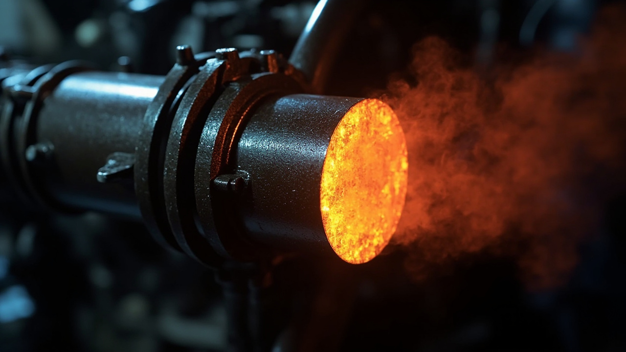
I. What is thermal shock: stress mutation driven by temperature difference
When a coating and substrate undergo rapid heating or sudden cooling, thermal stress arises due to asynchronous coefficient of thermal expansion (CTE, Coefficient of Thermal Expansion). The classic one-dimensional model gives the approximate maximum thermal stress within the coating:
σ_th ≈ E · Δα · ΔT / (1 − ν)
where E is the coating's elastic modulus, Δα = α_coating − α_substrate (CTE difference), ΔT is the temperature difference, and ν is Poisson's ratio. It can be seen that: the larger the CTE difference, the larger the temperature difference, and the harder the coating (high E), the higher the thermal stress. When the stress exceeds the coating's fracture strength or interfacial bond strength, cracking or delamination occurs.
Real conditions are more complex: during heating the coating is compressed due to substrate constraint, while during cooling/sudden cooling it is under tension—tensile stress is more likely to cause cracking, so "rapid cooling" is often more dangerous than "rapid heating." This is also why coatings are most prone to failure when exhaust pipes are splashed with cold water or power devices are switched off instantaneously.
II. Two routes to thermal shock resistance: CTE matching and stress absorption
There are two fundamentally different paths to improving thermal shock resistance:
1. CTE matching route: Select coating materials with CTE close to the substrate, reducing Δα at the root. For example, steel CTE ≈ 11–13 ×10⁻⁶ /K, aluminum ≈ 23 ×10⁻⁶ /K; pure Al₂O₃ ceramic CTE ≈ 8 ×10⁻⁶ /K is relatively close to steel, while some oxides differ greatly and require gradient transition.
2. Stress absorption/toughening route: Make the coating "hard yet not brittle"—absorb thermal stress through nano particle toughening, microcrack deflection, plastic deformation, porous buffering, etc. The main battlefield of nano coatings lies here.
Engineering often combines them: first use a gradient transition layer to match CTE, then apply a nano-toughened top layer, avoiding the trade-offs of a single material.
III. Nano toughening mechanism: why "nano" resists cracking
Nano particles (nano Al₂O₃, ZrO₂, SiC, TiO₂, SiO₂, etc.) contribute to thermal shock resistance through multiple microscopic mechanisms:
- Crack Deflection / Bridging: Nano particles form "roadblocks" ahead of crack tips, forcing cracks to detour and bifurcate, consuming fracture energy; ZrO₂'s transformation toughening (t→m phase transformation volume expansion) can even close cracks.
- Grain boundary pinning and grain refinement: Nano particles inhibit grain coarsening during coating sintering; fine grains enhance toughness (ceramic version of Hall-Petch relationship), reducing transgranular brittle fracture.
- Interface slip buffering: Appropriate nano pores/flexible interfaces allow local micro-slip, relieving stress concentration caused by CTE mismatch.
- Thermal conductivity regulation: High-thermal-conductivity phases like nano SiC can homogenize the temperature field and reduce local ΔT gradients; low-thermal-conductivity nano layers can also serve as thermal barrier (TBC) buffering.
It should be noted: nano toughening is the art of "moderation." Excessive nano particles or agglomeration introduce defects and instead reduce strength; the key is surface modification + uniform dispersion + compatibility with the matrix (silicone resin, ceramic precursor). This is consistent with the logic of nano dispersion in marine anti-corrosion.
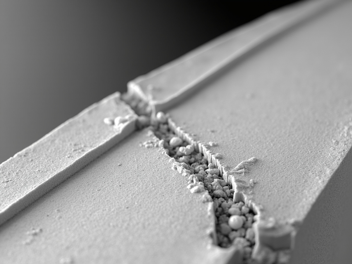
IV. Testing standards and methods for thermal shock resistance
Thermal shock resistance cannot be judged by feel; it must be quantified through standard methods:
| Test method | Common standards | Description |
|---|---|---|
| Coating film heat resistance | GB/T 1735-2009 "Determination of Heat Resistance of Coating Films" | After constant temperature in forced-air oven, evaluate appearance/adhesion changes |
| Heat resistant temperature | Manufacturer TDS heat resistance upper limit (e.g., 200/400/600℃) | Varies greatly depending on resin system |
| Thermal cycling | Custom or industry thermal shock procedure (heating—quench cycling) | Record number of cycles before cracking/delamination |
| Coefficient of thermal expansion | GB/T 7322 / equivalent thermomechanical analysis (TMA) | Measure CTE to match substrate |
| Adhesion (after heating) | GB/T 9286 cross-cut / GB/T 5210 pull-off | Compare failure degree before and after thermal shock |
According to public data, silicone heat-resistant coatings can work long-term in the 200–600℃ range, and higher short-term; but "heat resistant temperature" is a static indicator—thermal shock resistance depends on "number of cycles"—how many times it can go from 600℃ into cold water without cracking is the real-world criterion. When purchasing, request thermal cycle reports rather than a single heat resistance number.
V. Typical systems: from silicone to nano ceramic composites
Thermal shock resistant coatings are roughly graded by temperature resistance level:
- Silicone heat-resistant (200–600℃): Based on polysiloxane, with aluminum powder/glass frit added, commonly used for exhaust pipes, chimneys. Nano SiO₂ modification can improve thermal stability and adhesion. Advantage: easy application (room temperature curing); disadvantage: organic skeleton decomposes above 600℃.
- Nano ceramic composite (600–1000℃+): Sol-gel or plasma-sprayed Al₂O₃/ZrO₂/SiC nano composites, used for hot-section components. Requires high-temperature curing or sintering, high process threshold.
- Gradient thermal barrier (TBC, >1000℃): Aerospace engine YSZ (yttria-stabilized zirconia) nano-structured layer + metal bond layer, relying on low thermal conductivity and CTE gradient for dual thermal shock resistance; high-end but its "gradient" concept can be borrowed.
For most industrial customers (exhaust pipes, boilers, heat exchangers), the mid-temperature solution of silicone + nano modification offers the best cost-performance; only for ultra-high temperatures should ceramic composites or gradients be used. For selection of high-temperature coating (silicone), refer to the published technical article high-temperature coating (silicone).
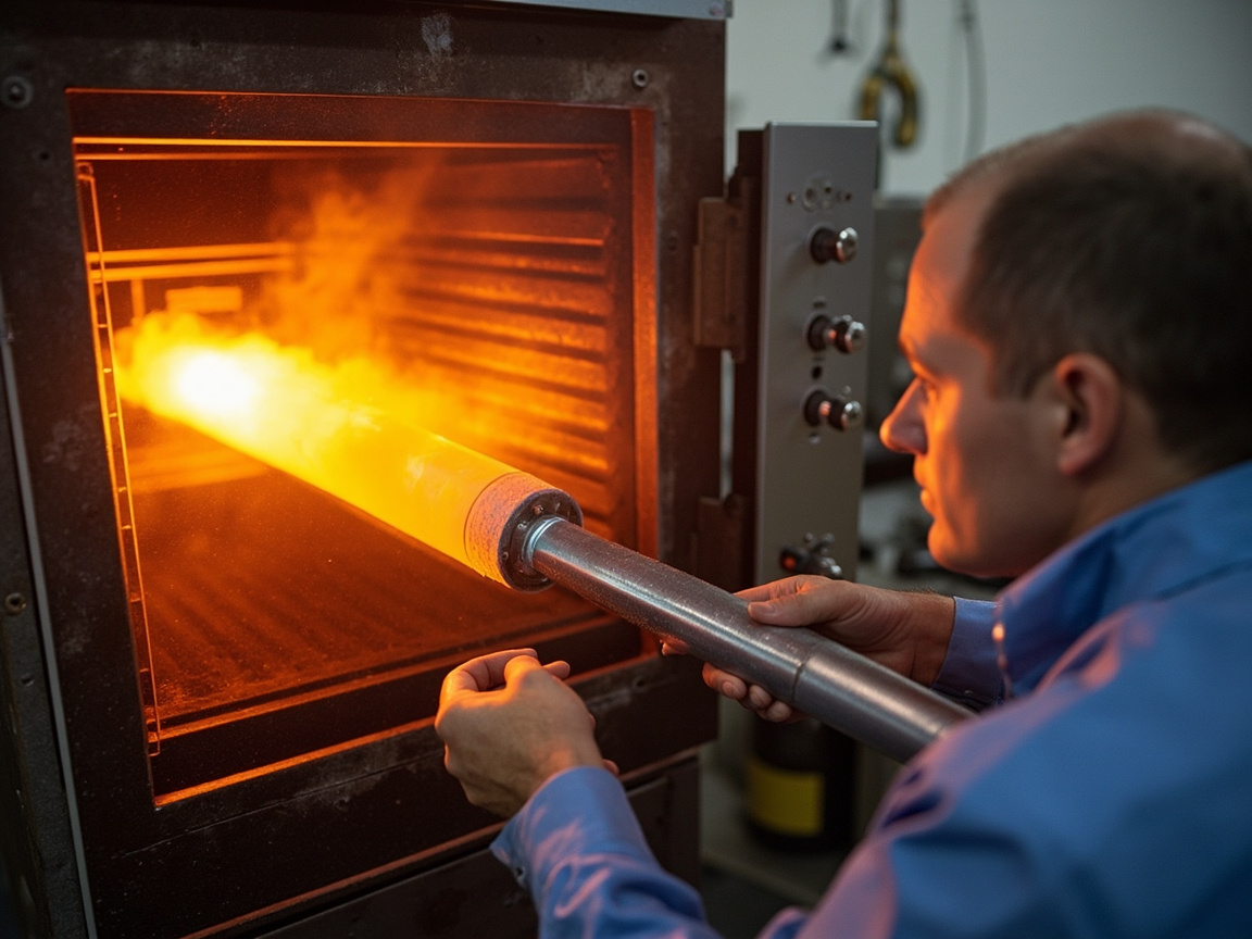
VI. Engineering calculation example of CTE matching
Suppose a steel substrate (α≈12×10⁻⁶/K) is to be coated with Al₂O₃ nano ceramic (α≈8×10⁻⁶/K), temperature difference ΔT=500K, coating E≈200 GPa, ν≈0.25. Substituting into σ_th ≈ E·Δα·ΔT/(1−ν) ≈ 200e9 × 4e-6 × 500 / 0.75 ≈ 533 MPa. If the coating's tensile strength < 533 MPa, cracking risk is high—this suggests either reducing Δα (adding transition layer to raise overall α close to 12), reducing E (toughening/porosifying), or limiting ΔT (slow cooling). This simplified model shows: thermal shock resistance is joint optimization of "material parameters + working conditions," and no single property can be viewed in isolation.
VII. Comparison and selection vs. conventional heat-resistant coatings
| Dimension | Ordinary silicone heat-resistant | Nano-modified thermal shock resistant coating |
|---|---|---|
| Temperature range | 200–600℃ | More stable in mid-temperature range, can extend to ceramic grade |
| Resistance to quench cracking | Average (hard and brittle) | Better (toughened to absorb stress) |
| Adhesion (after heating) | Prone to decline | More stable after nano modification |
| Application | Room temperature curing, simple | Slightly more process but controllable |
| Cost | Low | Medium |
| Applicable | Steady-state high temperature | Frequently alternating cold and hot conditions |
Selection principle: for steady-state high temperature with few abrupt changes, ordinary silicone is sufficient; for frequent rapid cooling and heating (such as intermittent furnaces, cold-water-splashed exhaust pipes), the incremental value of nano toughening is significant. For coating surface treatment and adhesion fundamentals, extend reading to the same batch ofNano coating application process.
8. Key Points for Construction and Quality Inspection
The hidden risk in the construction of thermal shock resistant coatings lies at the "interface": ① The substrate must be degreased and blasted (Sa 2½, ISO 8501-1 / GB/T 8923.1); both bare steel and the coating have large thermal expansion, and poor adhesion will inevitably cause delamination; ② If a transition layer is needed, strictly control the thickness gradient to avoid CTE jump; ③ Curing/sintering according to TDS; after room-temperature curing of silicone, post-curing at about 200℃ is recommended for complete crosslinking; ④ Quality inspection: perform cross-cut (GB/T 9286) and pull-off (GB/T 5210) tests both before and after thermal shock, and compare adhesion decay; ⑤ Record the number of thermal cycles and failure morphology (cracking/delamination/discoloration).
As a system supplier, Kexin New Materials (kexinMaterials), when delivering thermal shock resistant solutions, usually provides CTE gradient recommendations and post-curing windows for the "substrate—transition layer—top layer", and substantiates with thermal cycle reports, rather than merely labeling a static heat-resistant temperature—this is exactly the key to preventing customers from failing under real quenching conditions.
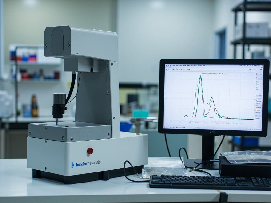
9. Common Failures and Countermeasures
High-frequency failures: ① Thermal shock cracking (CTE mismatch, coating too brittle) → add transition layer, nano toughening; ② Post-heat delamination (insufficient adhesion) → strengthen blasting and post-curing; ③ High-temperature powdering/carbonization (exceeding heat resistance) → reduce working condition or upgrade ceramic system; ④ Cumulative cold-hot fatigue (insufficient cycle count) → choose anti-cycle formulation rather than just looking at heat resistance. The countermeasure is the "four-piece set" of "match CTE + toughening + post-curing + thermal cycle verification".
10. Thermal Barrier Coating (TBC) Gradient Design Case
The "gradient" approach borrowed from aero-engines and gas turbine hot sections can be scaled down to industrial thermal shock resistance: the outermost layer is a low-thermal-conductivity ceramic (YSZ yttria-stabilized zirconia, or nano Al₂O₃/SiC composite) as thermal barrier, descending in order: nano composite transition layer (CTE between ceramic and metal) → metal bond layer (MCrAlY type, providing oxidation barrier and bonding). The gradient smoothly transitions CTE from metal at about 12×10⁻⁶/K to ceramic at about 8×10⁻⁶/K, avoiding CTE jump stress concentration at a single interface. Although industrial exhaust pipes do not reach thousand-degree levels, the two-layer gradient of "top layer + transition layer" can already significantly reduce quenching crack rate.
11. Experimental Methods for Quenching Rate and Critical ΔT
To determine thermal shock resistance, one must quantify "how large a ΔT can be withstood, and how fast the quenching is". Common methods:
| Method | Operation | Criterion |
|---|---|---|
| Direct quenching method | Heat to T then immerse in room-temperature water/oil | The lowest T at which cracking/delamination occurs is the critical ΔT |
| Thermal cycle method | Heat—hold—quench repeat | Record the number of cycles until failure |
| Quench temperature difference method | Set multiple ΔT gradient levels | Find ΔT₅₀ with 50% survival probability |
According to public literature, the critical ΔT of ceramic materials is consistent with the inverse derivation of the thermal stress formula; nano toughening systems can raise the critical ΔT by tens to over a hundred Kelvin compared to same-composition coarse-grain systems. When selecting, one should request "number of cycles" rather than a single heat-resistant temperature.
12. Quantification of Nano Toughening: Fracture Toughness and Stress Intensity Factor
"Hard yet tough" must be quantified by fracture mechanics, not just reported hardness:
- Fracture toughness K_IC (GB/T 4161 / ASTM E399 type): the material's ability to resist crack propagation, unit MPa·m¹ᐟ. Nano toughening (ZrO₂ phase transformation, particle bridging) is exactly what raises K_IC.
- Stress intensity factor K_I: the concentration of external stress at the crack tip; when K_I approaches K_IC, unstable propagation occurs.
- Residual stress: CTE mismatch of nano composites introduces residual stress, which needs to be evaluated by XRD sin²ψ method or indentation method, to avoid "toughening" being offset by residual stress.
As a system supplier, Kexin New Materials (kexinMaterials) routinely includes "K_IC + critical ΔT cycle + residual stress" as acceptance items in thermal shock resistant solutions, rather than just labeling a heat-resistant temperature—the latter is very prone to failure under real quenching conditions.
13. Coupled Design with Wear Resistance and Thermal Shock Resistance
Hot-section components often face both wear (particle erosion carried by airflow) and thermal shock. In design: ① top layer uses high-hardness nano Al₂O₃/SiC for erosion resistance; ② sub-layer uses ZrO₂ phase transformation toughening for thermal crack resistance; ③ interface uses gradient transition for CTE mismatch resistance. The ratio of the three is weighed according to "erosion rate vs quenching frequency" (see the wear mechanism classification in nano wear-resistant hard coating). Evaluating thermal shock resistance and wear resistance in the same failure tree can yield a coating system that is neither over- nor under-designed.
14. Quantifying "Sudden": Biot Number and Instantaneous Temperature Gradient
The destructive power of thermal shock depends not only on the temperature difference ΔT, but also on "how fast the cooling is". Heat transfer science uses the dimensionless Biot number to characterize this:
Bi = h · L / k
where h is the surface heat transfer coefficient (W/(m²·K)), L is the characteristic dimension (e.g., wall thickness), and k is the material thermal conductivity (W/(m·K)). The larger the Bi, the faster the heat exchange between the surface and the environment compared to the internal conduction, the more disparate the internal-external temperature difference, and the higher the transient thermal stress peak; when Bi is very small (thin wall, high conductivity, slow heat exchange), the interior is nearly isothermal and thermal stress is naturally low.
The engineering implication is very direct: the same 600℃ coated component, taken out and placed in still air for natural cooling (h usually only tens of W/(m²·K) order) almost never cracks; while directly thrown into room-temperature water for quenching (water quench h can be two to three orders of magnitude higher) may crack in one go. This explains why "exhaust pipe splashed by rain while driving", "continuous casting roll spray cooling", "heat-treated part water quenching out of furnace" are the most severe thermal shock scenarios, while slow cooling in furnace is almost harmless—the total temperature difference is the same, yet the damage degree is worlds apart.
From this, three actionable risk-reduction paths can be derived: ① Reduce h—use air cooling instead of water cooling, add insulation cover or slow-cooling section to extend heat exchange time; ② Reduce L—thin-walled parts and thin coatings have small internal gradients, while thick coatings accumulate larger gradient stress; ③ Increase k—introduce high-thermal-conductivity phases such as nano SiC, nano AlN to accelerate heat homogenization within the coating. All three suppress the "instantaneous temperature gradient" rather than change the total temperature difference itself. Understanding this, one can see why the same coating works in factory A but cracks in three months at factory B—the difference is often not the material, but the cooling method.
15. Kingery Thermal Shock Resistance Parameters: A Ranking Ruler at Material Level
In the field of ceramics and inorganic coatings, a set of thermal shock resistance parameters proposed by Kingery et al. is commonly used to rank materials, and can serve as a quantitative reference framework for material selection:
- R = σ_f(1−ν)/(E·α): thermal shock fracture parameter, dimension K, physically meaning "the critical temperature difference the material can theoretically withstand". σ_f is fracture strength, α is linear expansion coefficient, ν is Poisson's ratio, E is elastic modulus.
- R′ = k·σ_f(1−ν)/(E·α): based on R multiplied by thermal conductivity k, suitable for medium heat exchange rate (finite Bi) conditions, reflecting "whether thermal conductivity can cut the peak in time".
- R⁗ = E·γ_f/[σ_f²(1−ν)]: thermal shock damage parameter, γ_f is fracture surface energy, measuring "whether it can hold after cracking", the larger the value the harder the crack is to unstable propagate.
This set of formulas gives a counterintuitive but crucial conclusion: high strength does not necessarily mean thermal shock resistance. R is proportional to σ_f, while R⁗ is inversely proportional to σ_f²—a densely brittle ceramic that blindly pursues ultimate strength may have a high first-crack temperature difference, but once cracked it undergoes catastrophic propagation and instant delamination; conversely, a system that moderately reduces strength and significantly increases fracture energy (nano particle toughening, controlled microporosity, phase transformation toughening), although its first-crack ΔT is slightly lower, can survive long-term in hundreds to thousands of cold-hot cycles via "stable microcrack propagation".
What industrial thermal shock resistant coatings pursue is exactly the "damage tolerance" approach represented by the latter, which is completely consistent with the toughening logic of "hard but not brittle" in Section 3 of this article, and also explains why simply competing on hardness or strength numbers often fails to select a truly durable thermal shock resistant solution. If a supplier only reports hardness and maximum heat resistance, but cannot provide fracture toughness or thermal cycle count, it can basically be judged that they have not done design at the thermal shock level.
16. CTE Matching and Coating Strategy by Substrate Type
The primary issue of thermal shock resistance is Δα, and Δα is determined by the substrate. The linear expansion coefficients of common industrial substrates (typical ranges near room temperature, specific values subject to actual measurement by GB/T 4339, ASTM E228 push-rod method or ASTM E831 thermomechanical analysis) and layer selection strategies are as follows:
| Substrate type | Linear expansion coefficient α (10⁻⁶/K order) | CTE matching difficulty | Recommended coating strategy |
|---|---|---|---|
| Carbon steel / low alloy steel | About 11–13 | 3–5 units difference from oxide ceramic | Silicone heat-resistant top layer; add nano composite transition layer at high temperature section |
| Austenitic stainless steel (304/316) | About 16–18 | Higher than carbon steel, larger gap with ceramic | A gradient transition layer must be set; direct thick application of ceramic is prohibited |
| Cast iron | Approx. 10–12 | Graphite phase and matrix are non-uniform, with local stress concentration | First fully sandblast to remove graphite contamination, then apply thin coat of toughening system |
| Aluminum and aluminum alloys | Approx. 22–24 | Greatest gap with ceramic, and base material has low softening temperature | Use only medium- and low-temperature systems; prioritize flexible/microporous buffer layer |
| Titanium alloy | Approx. 8–10 | Close to alumina, good compatibility | Higher ceramic-content systems can be used |
| Dense Al₂O₃ ceramic | Approx. 7–8 | Inherently brittle, relies on toughening rather than matching | Nano toughening, control heating/cooling rate |
Key points for reading the table: Stainless steel is more difficult than carbon steel for thermal shock-resistant coating, which is contrary to many people's intuition—stainless steel has better corrosion and heat resistance, but its α is about 16–18×10⁻⁶/K, differing from Al₂O₃'s about 8×10⁻⁶/K by more than double; after substituting into σ_th ≈ E·Δα·ΔT/(1−ν), the thermal stress nearly doubles. Therefore, thick application of high-modulus ceramic on stainless steel hot-end parts is a typical misconception; it must be resolved by a gradient transition layer or low-modulus toughening layer. Aluminum alloys are limited by the base material itself; above 200℃ priority should be given to service downgrade rather than blindly stacking coatings.
17. Coating Thickness: Why "Thicker Means Less Thermal Shock Resistance"
In the field of anti-corrosion, "a bit thicker is safer" is common sense, but in the field of thermal shock resistance it is almost the opposite. There are three reasons:
First, strain energy accumulates with thickness. The elastic strain energy stored in the coating is approximately proportional to the thickness; when the energy is sufficient, cracks propagate spontaneously. Even if the stress is the same, a thin film has insufficient total releasable energy to drive long-range crack propagation, often forming only non-penetrating microcracks. This is the so-called critical thickness effect—the same formulation passes the cycle when thinly coated, but flakes off in sheets on the first cycle when thickly coated.
Second, thick coating amplifies the internal temperature gradient. From the Biot number relationship, it is known that increasing the characteristic dimension L directly raises Bi, widening the instantaneous temperature difference between the coating surface and interface, adding gradient stress.
Third, thick coating aggravates curing shrinkage residual stress. Silicone and sol-gel systems undergo volume shrinkage during curing/sintering; the residual tensile stress in thick films is greater, and when superimposed with thermal shock tensile stress it more easily exceeds the fracture threshold.
Therefore, in engineering, thermal shock-resistant coatings generally adopt "multi-pass thin coating" rather than "single-pass thick coating": each pass is controlled at the lower to middle value of the dry film thickness recommended in the manufacturer's TDS, with sufficient flash-off or stepwise heating between passes; the total thickness is limited to meet function without blind increase. Dry film thickness is measured point by point and recorded according to the magnetic/eddy current method of ISO 2808 or GB/T 13452.2, to avoid local over-thickness forming "stress islands". This is often overlooked in quality inspection: acceptance only checks "thickness not below the lower limit", but not "whether it exceeds the upper limit", resulting in the thickest area flaking first.
18. Key Points for Thermal Shock-Resistant Design in Four Typical Service Conditions
Case 1: Automotive/construction machinery exhaust manifolds and mufflers. The service condition is characterized by 400–700℃ cycles from frequent start-stop, local rapid cooling (high h) from rain/snow splashing during driving, and accompanying road gravel impact. Design points: topcoat selects nano SiO₂-modified silicone heat-resistant system, balancing medium-temperature stability and room-temperature workability; total thickness controlled in the thin film range; must perform post-curing around 200℃ for full crosslinking, otherwise powdering and loss of gloss occur on first high-temperature operation. Acceptance checks thermal cycle count and post-heat cross-cut adhesion (GB/T 9286 / ISO 2409), rather than solely the temperature rating.
Case 2: Industrial kilns and flues. The service condition is mainly steady-state high temperature, with slow cooling during intermittent shutdown; Bi is small and thermal shock pressure is actually low, but service time is extremely long and accompanied by flue gas corrosion. Design points: no need to over-pursue toughening; focus on long-term thermal stability and resistance to sulfur/alkali flue gas erosion; performance retention after long-term constant temperature can be evaluated following the approach of ASTM D2485 "Standard Test Method for Evaluating Coatings For Use at Elevated Temperatures".
Case 3: Metallurgical continuous casting rolls, heat treatment fixtures. The service condition is the most typical high-frequency rapid cooling and heating—spray water directly contacts the high-temperature roll surface, h is extremely high, and cycle count is in the tens of thousands. Design points: must follow the complete route of "gradient transition + nano toughening"; interface bond strength verified per ASTM C633 or GB/T 8642 (tensile bond strength of thermal spray coatings), and cycle count taken as the only meaningful acceptance indicator.
Case 4: Power electronic devices and heat dissipation substrates. Temperature difference amplitude is not large (often in the −40℃ to 150℃ range), but cycle count is extremely high (switching frequency), belonging to thermal fatigue rather than single thermal shock. Design points: focus on interfacial fatigue crack initiation under low-cycle/high-cycle thermal cycling; coating should be low-modulus and high-ductility; evaluate with specified-count temperature cycling test rather than single water quench. Failure in such conditions is often progressive delamination at the interface, barely visible to the naked eye before thousands of cycles, and must be tracked by adhesion re-test or ultrasonic/infrared nondestructive testing.
19. Thermal Shock-Resistant Coating Selection Decision Tree
For specific projects, judge layer by layer in the following order to avoid the inverted thinking of "look at the product first, then fit the condition":
Step 1 · Determine maximum service temperature. ≤200℃ can use conventional heat-resistant system without thermal shock specialization; 200–600℃ enters the silicone heat-resistant range; 600–1000℃ requires nano ceramic composite; >1000℃ consider gradient thermal barrier structure.
Step 2 · Determine whether rapid cooling exists. If cooling mode is furnace cooling or natural air cooling (low h), select per steady-state heat resistance; if water quench, spray, rain splashing, or forced air cooling (high h) exists, must initiate thermal shock specialization design.
Step 3 · Estimate order of magnitude of cycle count. Within hundreds belongs to low frequency, formulation margin can be relaxed; thousands to tens of thousands belongs to high-frequency thermal fatigue, must take cycle count as the core acceptance indicator and consider damage-tolerant (high R⁗) formulation.
Step 4 · Check base material CTE. Check the preceding classification table; if Δα is greater than about 5×10⁻⁶/K, gradient transition layer is mandatory; stainless steel and aluminum alloy substrates especially must not skip this step.
Step 5 · Superimpose other failure factors. Is there simultaneous erosive wear, flue gas corrosion, salt spray, oil contamination? If so, multi-failure coupling design is needed, not simply stacking two coatings.
Step 6 · Determine acceptance checklist. At least include: thermal cycle count (specify ΔT and cooling medium), pre- and post-heat adhesion comparison, temperature rating and basis, dry film thickness upper/lower limits, post-curing process parameters. Missing any item may lead to disputes after delivery.
20. Thermal Oxidation and Hot Corrosion: Coupled Failure Beyond Thermal Shock
Real hot-end components rarely face "pure temperature difference" alone. The following three coupling mechanisms often superimpose with thermal shock, jointly determining life:
Interface oxidation. At high temperature, oxygen diffuses through coating micropores and cracks to the interface, generating scale on the steel base surface. Oxidation products have larger volume than the original metal (Pilling-Bedworth ratio greater than 1), producing extra volumetric strain at the interface that "lifts" the coating. This is why many coatings are not directly cracked by thermal shock, but oxidize first then flake. Countermeasures are to increase coating density and introduce an antioxidant barrier layer (e.g., high-alumina-content system).
Hot corrosion. Sulfur, vanadium, sodium, etc. in combustion exhaust form low-melting-point molten salts in specific temperature zones, dissolving the coating's protective oxide film and accelerating erosion. Conditions burning heavy oil or biomass fuel are especially prominent. In such scenarios, simply improving thermal shock resistance is meaningless; medium compatibility must be solved first.
Thermal fatigue and creep. Under long-term high temperature, both coating and substrate may creep; after residual stress relaxes and then cools, a new stress state arises. Therefore "passing first thermal shock" does not mean "still passing after one thousand cycles"; accelerated evaluation must complete sufficient cycle count.
Conclusion: thermal shock-resistant design must be evaluated within a complete failure tree. Only testing water quench cycles without testing oxidation weight gain and medium compatibility may well fail in actual service to a completely different mechanism.
21. Quick Reference Table for Thermal Shock-Related Standards
There is no single standard covering all aspects of thermal shock resistance; engineering usually combines the following methods:
| Evaluation aspect | Standard number | Usage description |
|---|---|---|
| Coating heat resistance | GB/T 1735-2009 | After constant-temperature baking, evaluate appearance and adhesion change; static heat resistance baseline |
| Comprehensive evaluation of high-temperature coatings | ASTM D2485 | Evaluation method framework for high-temperature service coatings |
| Ceramic water quench thermal shock | ASTM C1525 | Water quench method for advanced ceramics to measure thermal shock resistance; can borrow its critical ΔT criterion |
| Coefficient of linear expansion (metal) | GB/T 4339 / ASTM E228 | Push-rod method to measure CTE, for Δα calculation |
| Coefficient of linear expansion (TMA) | ASTM E831 / ISO 11359-2 | Thermomechanical analysis, suitable for coatings and polymer systems |
| Coefficient of linear expansion (ceramic) | GB/T 16535 | Fine ceramic push-rod method |
| Thermal diffusivity/conductivity | GB/T 22588 / ASTM E1461 | Flash method to measure thermal diffusivity, derive k for Bi calculation |
| Fracture toughness (metal) | GB/T 4161 / ASTM E399 | Plane strain fracture toughness K_IC |
| Fracture toughness (ceramic) | ASTM C1421 | Advanced ceramic fracture toughness determination |
| Bond strength (thermal spray) | GB/T 8642 / ASTM C633 | Tensile bond strength of coating, core indicator of interface quality |
| Adhesion (cross-cut) | GB/T 9286 / ISO 2409 | Compare before and after heating, evaluate adhesion degradation |
| Adhesion (pull-off method) | GB/T 5210 / ISO 4624 | Quantitative MPa value, more sensitive than cross-cut |
| Dry film thickness | ISO 2808 / GB/T 13452.2 | Magnetic/eddy current thickness measurement, control upper and lower limits |
| Surface preparation grade | ISO 8501-1 / GB/T 8923.1 | Sa 2½ blast cleaning grade, prerequisite for interface success or failure |
Usage suggestion: Categorize the above table into three groups—"material parameters (CTE, k, K_IC)—interface quality (bond strength, adhesion, surface grade)—service verification (heat resistance, thermal cycling, oxidation)"—and write them into the technical agreement. The root cause of most thermal shock disputes is that both parties only agreed on the phrase "heat resistant 600℃", but did not agree on ΔT, cooling medium, cycle count, and failure morphology—and these four variables are what truly determine the acceptance result.
FAQ
Q: Is thermal shock resistance the same as heat resistant temperature?
A: No. Heat resistant temperature is a static indicator (e.g., no deformation under long-term exposure at 600℃), while thermal shock resistance is a dynamic indicator (how many times it can withstand sudden cooling from high temperature without cracking). Real working conditions are mostly alternating hot and cold, so thermal cycling reports should be reviewed rather than a single temperature number.
Q: Why is "rapid cooling" more dangerous than "rapid heating"?
A: During cooling/quenching, the coating is constrained by the substrate and subjected to tensile stress, and the material's tensile strength is usually lower than its compressive strength, making tensile stress more likely to cause cracking; during rapid heating the coating is under compression and relatively less likely to crack. Therefore, exhaust pipes splashed with cold water and devices instantly powered off are most prone to failure.
Q: How do nanoparticles make brittle ceramics crack-resistant?
A: Through crack deflection/bridging (particles force cracks to detour and consume fracture energy), ZrO₂ phase transformation toughening to close cracks, grain refinement to enhance toughness, and interfacial micro-slip to buffer stress. The key is uniform dispersion and appropriate amount; excess or agglomeration instead introduces defects.
Q: How important is CTE matching really?
A: Decisive. Thermal stress σ_th ≈ E·Δα·ΔT/(1−ν), the CTE difference Δα directly amplifies stress linearly. For steel substrates, select a coating with CTE close to 11–13×10⁻⁶/K or add a gradient transition layer, otherwise it will definitely crack. Calculate CTE first before discussing anything else in selection.
Q: How high can silicone heat-resistant coatings go?
A: Public data shows that polysiloxane-based heat-resistant coatings can work long-term at 200–600℃, and even higher for short periods; above 600℃ the organic skeleton decomposes, requiring nano ceramic composite or gradient thermal barrier. The specific upper limit is subject to the manufacturer's TDS.
Q: What standard is used to test thermal shock resistance?
A: Heat resistance of paint film can follow GB/T 1735-2009; CTE uses TMA-type methods (e.g., related to GB/T 7322); adhesion before and after heating uses GB/T 9286 cross-cut / GB/T 5210 pull-off method. Thermal cycle counts are mostly customized according to industry procedures or customer working conditions.
Q: What role does nano SiC play in thermal shock resistance?
A: Nano SiC has high thermal conductivity, which can homogenize the coating temperature field, reduce local ΔT gradient, and indirectly alleviate thermal stress; it also provides high hardness and wear resistance. However, the interface between SiC and the organic matrix needs modification to ensure dispersion and adhesion.
Q: Why is post-curing important?
A: After room-temperature curing of silicone coatings, internal cross-linking is often incomplete; post-curing at around 200℃ can fully cross-link, improve thermal stability and adhesion, and significantly enhance thermal shock performance. Skipping it leads to delamination and powdering after heating.
Q: What are the most common pitfalls in applying thermal shock resistant coatings?
A: Inadequate substrate preparation (no blast cleaning to Sa 2½) causes poor adhesion and immediate delamination after thermal expansion; or jumping CTE directly without a transition layer causes thermal stress concentration and cracking. The interface determines success more than the topcoat.
Q: Under what working conditions should nano thermal shock resistant be chosen over ordinary heat resistant?
A: For frequent rapid cooling and heating—intermittent furnaces, cold-water-splashed exhaust pipes, power device instant shutoff, metallurgical rolls with alternating cold and hot. For steady high temperature with few abrupt changes, ordinary silicone is more economical. Judge by "cycle count" rather than "temperature resistance".
Further Reading
- High-temperature coating (silicone): Establishes the selection and post-curing foundation for 200–600℃ silicone heat-resistant systems, which is the prerequisite for mid-temperature thermal shock solutions.
- Nano wear-resistant hard coating: Extends from hardness/toughness trade-off to understand the common toughening logic of "hard yet not brittle" in thermal shock and wear.
- Nano coating application process: From blasting, transition layer to post-curing, implementing reproducible construction and quality inspection of thermal shock resistant coatings.
- Automotive ceramic nano coating hydrophobic mechanism: full analysis from contact angle to durability
- Marine environment nano anti-rust coating: shielding, cathodic protection and nano enhancement under high salt spray
- Nano coating overview: nanoparticles, mechanism of action and definition boundaries