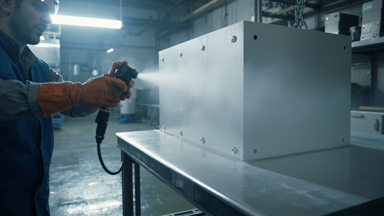
Modern electronic devices are packed with high-frequency digital circuits, switching power supplies, and wireless communication modules. Electromagnetic interference (EMI, the phenomenon referred to by the English abbreviation) has become a hard threshold for product reliability and compliance certification. Metal enclosures are naturally shielding bodies, but enclosure seams, observation windows, ventilation holes, and plastic housings all "leak electromagnetic waves." Conductive coating (conductive paint) forms a continuous conductive layer on the inner walls of plastic housings, at metal joints, and around shielding covers and connectors, "wrapping" the device in a continuous conductive cage (Faraday cage), thereby achieving EMI shielding. This article explains the technical key points of conductive coating EMI shielding thoroughly, from mechanism, fillers, coating types, key indicators, application to common failures.
As a technical supplier of functional coatings, Kexin New Materials (kexinMaterials) has accumulated a large amount of formulation and measured data on conductive and antistatic coatings, covering silver-based, nickel-based, carbon-based, and composite filler systems. This article breaks down the technical boundaries and selection logic of conductive coatings clearly, helping hardware and structural engineers incorporate coatings into the system scheme at the EMC design stage, rather than remedying afterwards.
I. Two Core Mechanisms of EMI Shielding
When electromagnetic waves encounter a conductive layer, they are mainly attenuated by three means. The industry often decomposes total shielding effectiveness (SE, in decibels) into three contributions: reflection, absorption, and multiple reflection:
- Reflection: The surface impedance of the conductive layer is far lower than the wave impedance of free space at about 377 ohms, and most of the incident wave is reflected back. The reflection term is strongly correlated with surface conductivity; high-conductivity metals such as silver and copper have the strongest reflection.
- Absorption: The wave entering the conductive layer attenuates inside the material, and the attenuation increases with conductivity, permeability, and thickness. Magnetic fillers (nickel, ferrite) contribute significantly to the absorption term.
- Multiple reflection: Multiple reflections inside a thin layer further dissipate energy, which often needs to be accounted for in thin coatings.
Total shielding effectiveness equals reflection plus absorption plus multiple reflection, in decibels. Every 10 dB corresponds to approximately 90% field strength attenuation. Common industry thresholds: consumer devices often require 30 to 40 dB, while military, medical, and communication equipment often require 60 to 80 dB or even higher. Specific indicators should be based on the whole-device EMC standard and project specification, not set by experience.
1.1 Skin Effect: The Physical Root of Absorption Loss
After high-frequency electromagnetic waves enter a conductor, current concentrates on the surface layer, and field strength decays exponentially with depth. The depth at which it decays to about 37% of the surface value is called skin depth. Skin depth is inversely proportional to the square root of the product of frequency, conductivity, and permeability: the higher the frequency and the better the material's conductivity and permeability, the smaller the skin depth, and the more sufficient the absorption of waves by a conductive layer of the same thickness. Taking high-conductivity copper as an example, the skin depth at 1 GHz is about 2 micrometers, and at 10 MHz it is about 20 micrometers. This explains two engineering phenomena: first, a conductive coating tens of micrometers thick can already provide considerable absorption loss in the GHz band, because the film thickness is equivalent to several skin depths; second, at low frequencies in the kHz range, the shielding capability of non-magnetic conductive coatings drops sharply, because the skin depth far exceeds the film thickness, and high-permeability magnetic materials are needed to be effective. Engineering evaluation of low-frequency magnetic field shielding and high-frequency electric field shielding must be separated; one dB number cannot cover the full frequency band.
1.2 Near Field and Far Field: Distance Determines Shielding Strategy
The region less than about one-sixth of the wavelength from the interference source is called the near field, and greater than that is the far field. The near field is further divided into electric-field-dominated (high-impedance source, such as high-voltage low-current switching nodes) and magnetic-field-dominated (low-impedance source, such as high-current loops, transformers). Electric-field near field is easily reflected by high-conductivity thin layers, and conductive coatings perform well; magnetic-field near field is difficult to reflect and mainly relies on absorption, which is extremely unfriendly to coatings at low frequencies. Far-field plane waves are in between, with reflection and absorption both playing a role. This division is of great significance to device design: shielding the near-field magnetic leakage of a switching power supply transformer and suppressing the far-field radiated emission of a whole device are two completely different problems—the former may require a local magnetic shield, while the latter is the main battlefield of conductive coatings. Before selection, first clarify the interference source type, frequency band, and source distance, which is the first step to avoid "coating but useless." For whole-device radiated emission limits, refer to the national standard 9254.1 for information technology and multimedia equipment (corresponding to CISPR 32), and for immunity test methods refer to the national standard 17626 series (corresponding to IEC 61000-4 series).
II. Conductive Fillers: Silver, Nickel, Copper, and Carbon Each Have Their Strengths
The performance of conductive coatings is jointly determined by "filler, resin, and dispersion process." Mainstream filler characteristics are as follows:
2.1 Silver Powder and Silver-coated Copper
Highest conductivity, good oxidation resistance, excellent shielding (up to 60 to 80 dB), but high cost, mostly used in high-end and high-reliability scenarios. Silver migration risk (silver migration, i.e., silver ions migrating along the surface to form dendrites under humid and biased conditions) needs attention in humid and energized environments, and can be mitigated through encapsulation and anti-migration design.
2.2 Nickel Powder
Moderate cost, magnetic contribution to absorption, oxidation resistance better than copper, common shielding of 40 to 60 dB, mainstream in commercial and some military applications. The magnetic loss characteristic of nickel powder makes its absorption performance in mid-low frequency bands better than pure silver systems.
2.3 Copper Powder
Good conductivity but easily oxidizes and turns black with conductivity decay; surface treatment (silver plating or coating) is required to maintain stable electrical performance. Bare copper powder has poor long-term reliability, and industrially silver-plated copper or nickel-coated copper is often used instead.
2.4 Carbon-based (Graphite, Carbon Black, Carbon Nanotubes)
Low cost, corrosion resistant, but conductivity far lower than metals, general shielding of 30 to 40 dB, suitable for antistatic and light shielding with low requirements; carbon nanotubes can improve network efficiency and enhance conduction at the same filler loading.
2.5 Composite Fillers
Silver-coated copper, nickel-coated graphite, etc., balance cost and performance through composite design, and are an important direction for mass-production cost-effective solutions.
2.6 Filler Morphology and Percolation Threshold: Why Flakes Are More Efficient
Whether a conductive coating is conductive depends on whether the filler particles can interconnect in the resin to form a penetrating network; this critical point is called the percolation threshold. Classical percolation theory gives a threshold of about 16% by volume fraction for randomly distributed spherical particles, while flake, dendritic, and fibrous fillers have much lower thresholds due to high aspect ratio and large "coverage" per particle—the higher the aspect ratio, the lower the volume fraction required to form a network. This is why conductive paints mostly use flake silver powder, dendritic nickel powder, and flake graphite rather than spherical powder: at the same conductivity level, flake systems require less filler, which is more favorable in cost, density, adhesion, and flexibility. Two engineering details are worth noting. First, particle size distribution matching: large flakes undertake main conduction, fine powder fills inter-flake gaps; bimodal gradation is often better than single particle size. Second, orientation during film formation: after spraying, flake fillers tend to align parallel to the substrate in the film, with good lateral conduction but relatively weak conduction in the film thickness direction; therefore, qualified square resistance measurement does not mean qualified interlayer conduction and grounding transition resistance, and the actual resistance from coating to ground point should be additionally measured during acceptance. In addition, the filler surface state directly determines contact resistance: the oxide film on nickel powder surface and lubricant residue on silver powder surface both raise inter-particle contact resistance; the formulation needs surface treatment and resin shrinkage compaction to ensure tight inter-particle contact, which is also the root cause of huge square resistance differences among products from different manufacturers at the same filler content.
III. Comparison of Conductive Coating Types
Systems with different matrices and fillers differ significantly in shielding effectiveness, cost, and process:
| Coating Type | Matrix Resin | Main Filler | Shielding Effectiveness | Features |
|---|---|---|---|---|
| Silver Conductive Paint | Epoxy or Acrylic | Silver Powder | 60 to 80 | Excellent performance but high cost |
| Nickel Conductive Paint | Epoxy or Polyurethane | Nickel Powder | 40 to 60 | Good cost-performance, with absorption |
| Copper Conductive Paint | Epoxy | Copper or Silver-plated Copper | 50 to 70 | Easy to oxidize, needs treatment |
| Carbon Conductive Paint | Epoxy | Carbon Black or Graphite | 30 to 40 | Cheap, corrosion resistant |
| Conductive Polymer | Resin | Intrinsically Conductive Polymer | Low to Medium | Special scenarios |
It should be noted that the shielding effectiveness ranges in the table are common industry magnitudes; actual values depend on film thickness, filler volume fraction, conductive network continuity, and test method (coaxial method, waveguide method, flange coaxial method, etc.), and dB numbers cannot be discussed without test conditions.

IV. Key Indicators and Standards
4.1 Surface Resistance and Volume Resistance
Conductive coatings are characterized by surface resistance (sheet resistance, unit ohm per square) and volume resistivity (unit ohm-centimeter). EMI shielding requires sufficiently low sheet resistance (e.g., below the order of 1 ohm per square for high shielding); antistatic (electrostatic prevention) usually requires surface resistance in the range of 10^5 to 10^8 ohms (refer to national standard 13348 and related antistatic specifications), and the two goals are completely different.
4.2 Shielding Effectiveness Standards
- National Standard 30142 "Measurement Method for Shielding Effectiveness of Electromagnetic Shielding Materials": Specifies measurement methods such as coaxial method, waveguide method, and flange coaxial method, and is a common basis for acceptance of domestic shielding materials;
- IEEE 299: Test method for shielding enclosures;
- US Military Specification 83528: Military specification for conductive shielding gaskets and coating materials, including shielding requirements;
- IEC and CISPR Series: EMC limits and measurements at the whole-device level.
When selecting coatings, suppliers should be required to provide test reports for corresponding methods and frequency bands, rather than just a single total dB number.
4.3 Adhesion and Durability
Conductive fillers often reduce coating adhesion and flexibility, requiring a balance in formulation. Adhesion is verified by the cross-cut method according to national standard 9286, and weather resistance and salt spray are evaluated according to ISO 12944 and national standard 10125. For scenarios requiring both shielding and outdoor durability, topcoat protection design cannot be ignored.
4.4 Differences Among Three Test Methods and Report Interpretation
For the same coating, shielding effectiveness measured by different methods cannot be directly compared. National Standard 30142 uses flange coaxial and similar devices to test planar samples; the fixture and frequency band design determine that it is suitable for material-level comparison and incoming material inspection; ASTM Standard D4935 also targets planar materials, covering far-field plane wave conditions from 30 MHz to 1.5 GHz; while IEEE Standard 299 is oriented toward complete shielded enclosures or shielded rooms, measuring "structural-level" effectiveness, including the effects of seams, openings, and grounding. The three levels are different: high material-level data does not mean structural-level compliance, because overall leakage is often dominated by seams and openings rather than the material itself. Surface resistance measurement is performed according to the methods and electrode arrangements of National Standard 1410 or ASTM Standard D257; square resistance data must specify the test voltage and electrode type to be comparable. When interpreting shielding reports, four things should be confirmed: test method and frequency band, sample film thickness and preparation method, whether seam or opening structures are included, and whether the data is a single-point value or a full-frequency-band curve. Promotional data that only gives "80 dB shielding" without attaching the method and frequency band cannot be trusted in engineering.
V. Construction Key Points: Continuity Is the Lifeline
The biggest fear for electromagnetic interference shielding coatings is "discontinuity," because a single discontinuity can form a leakage window. Construction key points:
- Substrate Treatment: Plastic housings should undergo adhesion treatment (flame or plasma), metal housings should be degreased and derusted to ensure the coating bonds with the substrate;
- Film Thickness and Coverage: Ensure the filler forms a continuous conductive network; insufficient film thickness breaks the network and causes a sharp drop in shielding;
- Edges and Seams: Housing joints, screw holes, and ventilation windows must be continuously covered, or supplemented with conductive gaskets (conductive adhesive, beryllium copper springs) to fill gaps;
- Reliable Grounding: The conductive layer must be reliably connected to the equipment ground; a Faraday cage without grounding greatly reduces the shielding effect;
- Environmental Control: Temperature and humidity should be controlled, two-component materials should be prepared strictly according to the mixing ratio, and appearance and adhesion should be accepted according to corresponding national standards.
In terms of spraying parameters, conductive coatings differ from ordinary industrial paint in several ways. First, conductive fillers have high density and are prone to settling; they must be thoroughly stirred before construction and kept agitated during the process, otherwise the filler content of the first and last sprayed areas will differ and the square resistance will drift. Second, atomization pressure and gun distance affect the orientation and packing density of flake fillers; excessive atomization will break the flakes and reduce conductivity, so it should be executed according to the supplier's process window and the square resistance of the first piece should be measured for confirmation. Third, film thickness measurement must distinguish substrates: on metal substrates, the common method for coating thickness measurement can be used; on plastic substrates, both magnetic and eddy current methods are not applicable. In engineering, wet film gauges are often used to convert to dry film thickness based on solid content, or cross-section microscopy is performed on samples. In mass production, process parameterCuring plus first and last piece square resistance sampling is used to control consistency. Fourth, multiple thin coats are better than one thick coat; sufficient flash-off time between layers should be allowed to avoid solvent trapped in the film forming pinholes—pinholes are discontinuities in electrical performance and entry points for corrosion and moisture absorption in reliability.

VI. Difference Between Conductive Coating and Static-Dissipative Coating
The two are often confused, but their purposes and indicators differ:
- EMI Shielding: Requires low square resistance (below the order of 1 ohm per square), high shielding dB, to prevent electromagnetic leakage and interference;
- Static Dissipation (Antistatic): Surface resistance in the range of 100 kΩ to 100 MΩ, safely conducting static charges to ground, used for explosion protection (such as storage tanks, and the anti-corrosion station equipment for hydrogen energy storage and transportation discussed in this batch).
Different purposes mean different formulations and acceptance indicators, and they cannot be used interchangeably. A common mistake is using a static-dissipative coating as an EMI shielding coating on high-frequency equipment housings, resulting in failure to meet shielding requirements.
VII. Relationship with Graphene Conductive Coating
In the graphene conductive anti-corrosion coating discussed in this batch, graphene is also a conductive filler that can build a network in small amounts and also provide anti-corrosion; but pure EMI shielding more commonly uses silver and nickel systems to achieve higher dB. Graphene is suitable for "anti-corrosion plus lightweight static dissipation" integration scenarios. When selecting filler routes, one should consider frequency band, cost, anti-corrosion, and process maturity comprehensively.
VIII. Common Failures and Countermeasures
| Failure Phenomenon | Main Cause | Countermeasure |
|---|---|---|
| Shielding below standard | Thin film, broken network | Increase thickness, ensure continuity |
| Seam leakage | Joint not covered | Conductive gasket to fill seam |
| No grounding | Conductive layer not connected to ground | Reliable grounding |
| Poor adhesion | Too much filler, poor pretreatment | Balance formulation, strengthen treatment |
| Silver migration | Humid heat with bias | Select migration-resistant system or encapsulation |
Kexin New Materials (kexinMaterials) emphasizes the dual factors of "filler network plus grounding continuity" in conductive coating solutions. It provides both highly conductive silver and nickel systems and plastic housing adhesion process schemes, avoiding the awkward situation of "coating is conductive but the whole device still exceeds limits." At the same time, it warns of copper system oxidation and silver migration risks in material selection, helping customers match systems according to frequency band and reliability requirements.
IX. Horizontal Comparison of Shielding Schemes: Coating Is Not the Only Option
There are multiple technical routes to achieve electromagnetic shielding for plastic housings, and conductive coating is only one of them; selection should be compared horizontally:
| Scheme | Typical Shielding Level | Cost | Process Characteristics | Applicable Scenario |
|---|---|---|---|---|
| Conductive coating spraying | Medium to high | Medium | Flexible modification, local treatment possible | Small to medium batch, multi-variety housings |
| Electroless copper/nickel plating | High | Medium-high | Uniform full surface, difficult waste liquid treatment | Large batch finalized products |
| Vacuum aluminum plating | Medium | Medium | Thin film, dead corners in complex cavities | Simple-shaped housings |
| Conductive plastic (filler blend) | Low to medium | High (mold and material) | One-step molding, no secondary process | Very large batch, moderate shielding requirement |
| Metal housing or metal liner | High | High | Heavy weight, many design constraints | High reliability, military and medical |
The core advantage of the coating route is flexibility: change model without changing mold, can only treat areas needing shielding, and can cooperate with conductive gaskets to fill seams; the disadvantage is an extra spraying process and dependence on pretreatment quality. For products with very large annual output and low shielding requirements, conductive plastic one-step molding may have better total cost; for high requirements above 60 dB, electroless plating or the combination of "coating plus gasket plus structural design" is more stable. Scheme comparison should be based on the total cost of the whole device meeting the standard, rather than just the coating price per square decimeter.
X. Typical Application Scenarios and Selection Decisions
Combined with engineering practice, the selection key points for common scenarios are summarized as follows.
Communication and Network Equipment: Operating frequency up to several GHz, strict radiated emission limits; plastic housing inner walls mostly use nickel or silver coatings, focusing on controlling the opening size of heat sink hole arrays and the continuity of coating on hole walls. The aperture should be far smaller than the wavelength corresponding to the highest frequency of concern; if necessary, use waveguide cutoff ventilation window structure.
Medical Electronic Equipment: It must prevent external interference from affecting measurement accuracy and control its own emission; shielding requirement often above 60 dB, tending to silver coating or electroless plating route, with additional requirements for coating cleaner resistance and low volatility. Acceptance is based on whole-device medical EMC standards rather than material-level data.
Automotive Electronic Control Unit: Vibration, temperature cycling, and humid heat combined; the weight of coating adhesion and durability is higher than the limit shielding value. Nickel coating plus reliable grounding design is mainstream; engine compartment parts also need to evaluate oil and temperature resistance, and re-measure square resistance after temperature cycling.
Consumer Electronics and Drones: Sensitive to weight and cost; carbon or low-content nickel coatings combined with board-level shielding cans are used. The coating handles the overall housing, and the shield can handles sensitive modules. This layered design is more economical than relying solely on thicker coating, and easier to adjust locally during revision.
The selection decision can be done in four steps: Step 1, clarify the EMC standard and limit the whole device must meet, and back-calculate the shielding amount the housing needs to contribute; Step 2, judge the weight of reflection and absorption by frequency band, determine the filler route—high frequency prioritizes high-conductivity fillers, low-frequency magnetic field needs consider magnetic fillers; Step 3, select the process route (coating, electroless plating, or conductive plastic) according to substrate, structural complexity, and output; Step 4, do pre-compliance testing on the prototype to verify, focusing on seams, cable exits, and grounding. If unqualified, prioritize fixing structural defects rather than blindly thickening the coating. The greatest value a coating supplier can provide is often not the paint itself, but the experience list of "where it will leak," so it is recommended to introduce the coating party and EMC engineer for joint review before the structure is frozen.
Finally, a directly implementable mass production acceptance checklist is provided for the quality department: in appearance, no missed spray, sagging, pinholes, or obvious color difference, and complete coverage at opening edges and seams; in electrical performance, measure square resistance by sampling plan and record measurement point locations, and separately measure the transition resistance from coating to grounding stud with an upper limit; in mechanical performance, do cross-cut adhesion sampling, and if necessary add a second tape peel test for confirmation; in reliability, arrange square resistance re-measurement after humid heat and temperature cycling by batch frequency; in documentation, retain coating batch number, mixing ratio record, environmental temperature and humidity record, and first-piece test data to form a traceable closed loop. Most shielding coating quality problems are not "bad paint" but process out of control—managing process data is much cheaper than post-rectification.
FAQ
Q: What is the concept of EMI shielding effectiveness in dB?
A:Decibels indicate the attenuation factor; every 10 dB corresponds to approximately 90% attenuation of field strength. Consumer products often require 30 to 40 dB, while military and medical applications may require 60 to 80 dB. Total shielding effectiveness equals reflection plus absorption plus multiple reflections, and must be interpreted in conjunction with frequency band and test method.
Q: How to choose silver, nickel, and carbon conductive paint?
A: Silver offers the highest shielding (60 to 80) but at high cost; nickel provides good cost-performance (40 to 60) and has magnetic absorption, making it the mainstream for commercial and some military uses; carbon is cheap and corrosion-resistant but has low shielding (30 to 40), suitable for light shielding or anti-static. Choose based on frequency band, reliability, and budget.
Q: What surface resistance qualifies as a qualified conductive coating?
A: EMI shielding often requires sheet resistance on the order of below 1 ohm per square; static dissipation (anti-static) is 100,000 to 100,000,000 ohms. The two metrics differ and must be determined by application; they should not be confused.
Q: Is a conductive coating useful without grounding?
A: Basically ineffective. A Faraday cage must be connected to equipment ground to divert interference into the earth; coating alone without grounding greatly reduces shielding. Grounding continuity is a key acceptance item.
Q: Can a plastic enclosure provide EMI shielding?
A: Yes. Spraying a conductive coating on the inner wall of the plastic shell to form a continuous conductive layer and grounding it creates a shielding cage. The difficulty lies in plastic adhesion and pretreatment, as well as continuous coverage of seams and windows, which requires coordination with structural design.
Q: Does a conductive coating affect corrosion protection?
A: Conductive metal fillers (especially copper) may accelerate galvanic corrosion at damaged spots; choosing corrosion-resistant nickel or carbon systems or adding an anti-corrosion primer can mitigate this. Corrosion protection and conductivity require coordinated design; one should not be pursued at the expense of the other.
Q: What is the risk of silver migration?
A: Under humid-heat and bias conditions, silver ions migrate along the surface to form dendrites causing short circuits, affecting reliability. High-end and humid powered scenarios use anti-migration formulations or encapsulation protection.
Q: What standards verify shielding?
A: National Standard 30142 (shielding effectiveness measurement), IEEE 299 (enclosures), MIL-SPEC 83528 (military materials), and for whole-device EMC refer to IEC and CISPR series. Require suppliers to provide corresponding test reports.
Q: How do conductive coatings and conductive gaskets work together?
A: Coatings handle large-area continuous shielding; gaps and removable covers use conductive gaskets (conductive adhesive, spring contacts) to supplement continuity; both grounded is most reliable. Especially on frequently disassembled structures, gaskets are a necessary supplement.
Q: Does thicker film mean better shielding?
A: After forming a continuous network, increasing thickness can improve absorption contribution, but with diminishing returns; more critical is "continuous without breaks plus grounding". Excessive thickness instead causes cracking, added weight, and cost; reasonable film thickness should be determined by test data.
Q: Do heat sinks and display windows break shielding?
A: Yes, openings are the main leakage path of enclosure shielding. Engineering controls the maximum opening size far below the wavelength corresponding to the frequency of concern; multiple small-hole arrays are better than a single large hole; display windows can use conductive glass or metal mesh interlayers, and vents can use waveguide-beyond-cutoff ducts. The coating must continuously cover to the opening edges and form reliable electrical contact with these shielding elements.
Q: How to assess long-term reliability of conductive coatings?
A: Define items by system and environment: nickel and carbon systems perform better in humid-heat and salt spray, silver systems need attention to sulfidation discoloration and migration, copper systems need attention to oxidation attenuation. Acceptance should retest sheet resistance and adhesion after humid-heat and thermal cycle tests; electrical performance attenuation must be within the limits allowed by the specification, not just initial values.
Further Reading
- Graphene Conductive Anti-Corrosion Coating: Flake Shielding and Conductivity: Extends the conductive filler concept to graphene-based anti-corrosion plus conductive composite systems.
- Hydrogen Energy Storage and Transportation Anti-Corrosion: Protection of Hydrogen-Exposed Equipment: Understand the application logic of static-dissipative coatings in explosion-proof station equipment.
- Electronic Control Box Conformal Coating: Circuit Board Protection: Extends from enclosure shielding to internal circuit three-proof protection, forming a complete EMI and protection solution.
- Electronic Three-Proof Nano Coating: Principles of Ultra-Thin Protective Film and Electronic Protection Applications
- Charging Pile Outdoor Weather-Resistant Coating: Long-Term Protection System for Charging Facility Enclosures
- Nano Coating Overview: Nanoparticles, Mechanisms, and Definition Boundaries