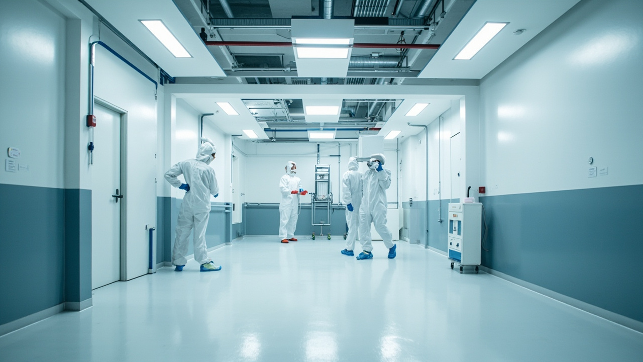
Semiconductor manufacturing is one of the industrial scenarios with the highest requirements for environmental cleanliness. The line width of an advanced logic chip is only a few nanometers; a single 0.1 µm dust particle landing on a wafer may cause a short circuit or yield collapse. At the same time, processes such as photolithography, etching, ion implantation, and CMP extensively use strong acids (hydrofluoric acid, sulfuric acid), strong alkalis, and organic solvents, and are extremely sensitive to electrostatic discharge (ESD). The "shell" of the cleanroom—walls, ceilings, floors, doors, windows, and return air ducts—must rely on a special coating system to achieve: low outgassing, non-particle-generating, anti-static, chemical-resistant, and easy to clean.
Kexin New Materials (kexinMaterials) has made continuous investment in protective coatings for cleanrooms and electronic factories. This article systematically explains the technical key points of "semiconductor cleanroom coating" from standard classification, failure risks, material mechanisms, chemical resistance comparison to construction selection, for reference by facility, process, and material engineers.
I. Four Challenges Faced by Cleanroom Coating
Semiconductor cleanroom coatings are not ordinary floor paint; they must simultaneously meet seemingly contradictory requirements:
- Non-particle-generating, low outgassing: The coating itself must not shed particles, nor release volatile organic compounds (VOC, plasticizers, siloxanes) that contaminate wafers or adsorb on optical lenses. Certain outgassing molecules form "haze defects" during the exposure process, directly lowering the yield.
- Anti-static / ESD control: Static electricity adsorbs dust and breaks down sensitive devices. Floors and walls need to control surface resistance within zoned ranges, both dissipating charge without causing sparks.
- Chemical corrosion resistance: Must tolerate frequent splashing and cleaning by HF, H₂SO₄, HNO₃, H₃PO₄, NaOH, TMAH, IPA, photoresist removers, etc.
- Seamless and easy to clean, curved transition: Reduce dust accumulation dead corners, and withstand frequent wiping and disinfectants (such as isopropanol, hydrogen peroxide).
These four points jointly determine that the coating formulation must be a low-VOC, solvent-free or water-based epoxy/polyurethane system, and contain conductive fillers to achieve static dissipation.
II. Cleanroom Classification and Reference Standards
Cleanliness is classified by the number of particles of specific sizes per unit volume of air. Internationally, ISO 14644-1 (corresponding to national standard GB 50073-2013 "Design Code for Clean Plant") is used, classifying cleanrooms into ISO Class 1–9 according to the number of particles ≥0.1 µm per cubic meter. The front-end photolithography area of semiconductors often requires ISO Class 3–5 (approximately old Class 1–100), while back-end packaging may be relaxed to ISO 6–7.
| Cleanliness class | Number of particles ≥0.1 µm (pcs/m³, approx.) | Typical semiconductor area |
|---|---|---|
| ISO Class 3 | ≈35,200 | Photolithography, advanced front-end |
| ISO Class 4 | ≈352,000 | Etching, thin film |
| ISO Class 5 | ≈3,520,000 | Diffusion, ion implantation |
| ISO Class 6 | ≈35,200,000 | Packaging, testing |
| ISO Class 7 | ≈352,000,000 | Auxiliary area, support area |
Test methods are based on ISO 14644-3 (sampling, concentration, air velocity, pressure difference, self-cleaning). Air change rate, pressure differential gradient (adjacent rooms ≥5–10 Pa positive pressure difference), and "unidirectional flow" air velocity also affect the selection of the coating system—wall and ceiling coatings must withstand sustained airflow and filter vibration.
Wall and ceiling materials must also meet non-combustible, low-smoke and non-toxic requirements (such as GB 8624 combustion rating); floors must be anti-slip, wear-resistant, and able to bear equipment and forklifts.
III. Coating System Composition: Walls, Ceilings, Floors, Joints
- Floor: Mainstream is solvent-free epoxy self-leveling or PU mortar, thickness 2–4 mm, seamless, wear-resistant, chemical-resistant; high-grade areas use anti-static epoxy (conductive filler).
- Wall/ceiling: Color steel plate (rock wool/magnesium oxysulfate core) surface roller-coated or sprayed with clean topcoat, or epoxy troweling + topcoat on concrete wall; requires dense surface, wipeable, non-chalking.
- Cove: Wall-floor junction, wall-ceiling junction made with R≥30 mm curve to eliminate right-angle dust accumulation, using special cove strip or mortar arc troweling then coating.
- Doors, windows and return air: Aluminum alloy/stainless steel frame with smooth coating, return air opening periphery given chemical-resistant reinforcement.
- Joint treatment: All joints sealed with elastic weather-resistant, chemical-resistant sealant to avoid cracking and particle generation.
IV. Low Outgassing Mechanism and Material Selection
"Outgassing" refers to the slow volatilization at room temperature of unreacted monomers, residual solvents, plasticizers, and silicone oil in the coating. The semiconductor scenario is especially sensitive to siloxanes (silicon is a chip killer), so cleanroom coatings must be silicone-free.
Means to reduce outgassing:
- Solvent-free system: According to the low-VOC direction of GB 30981-2020 "Limit of Harmful Substances in Industrial Protective Coatings", adopt 100% solid content epoxy/polyurethane to eliminate solvent residue.
- Full curing: Increase crosslink density, reduce migratable small molecules; bake or extend curing until outgassing meets standard.
- Avoid easily migrating additives: Do not use silicone leveling agents, phthalate plasticizers; use high molecular weight polymeric additives instead.
- Material identification: Refer to SEMI series standards for outgassing and metal ion extraction requirements of cleanroom materials, perform thermal desorption-GCMS screening on suspected batches.
Kexin New Materials (kexinMaterials) adopts a silicone-free, low-migration route in its cleanroom topcoat formulation, precisely to pass the strict haze defect threshold of wafer fabs.
V. Anti-static and ESD Control
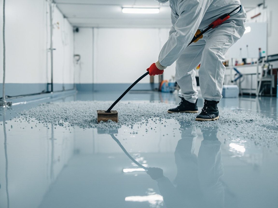
The harm of static electricity to semiconductors runs through the entire manufacturing process. The coating forms a dissipative network through conductive fillers (conductive carbon black, carbon fiber, metal oxide, graphene, see graphene conductive anti-corrosion coating) to control surface resistance within the target range:
- ESD static dissipative: Surface resistance 10⁶–10⁹ Ω, safely dissipates charge after grounding, used for personnel activity area floors, workbench surfaces;
- Anti-static: 10⁹–10¹¹ Ω, suppresses dust adsorption, used for walls, ceilings;
- Conductive: <10⁶ Ω, used for special grounding channels.
The static control system is based on ANSI/ESD S20.20 and IEC 61340-5-1 (corresponding to GB/T 32304, etc.), emphasizing grounding, personnel wrist straps, shoe straps, and the overall resistance chain of furniture and floor; the coating is only one link. The floor needs copper foil or conductive primer grounding grid, the surface conductive path connects with it, and is regularly tested for decay and resistance using a surface resistance meter (such as ANSI/ESD STM11.11 method).
VI. Chemical Resistance: The Test of Strong Acids and Alkalis
The chemical list of semiconductor processes is a "corrosion全家桶" for coatings. The table below compares the effects of typical media on unprotected concrete/ordinary epoxy and specialized chemical-resistant cleanroom coatings:
| Chemical medium | Concentration/scenario | Ordinary epoxy | Phenolic/vinylester modified epoxy | PU mortar |
|---|---|---|---|---|
| Hydrofluoric acid HF | Dilute to concentrated, etching cleaning | Severe damage (fluorine penetration) | Relatively good (special required) | Moderate |
| Sulfuric acid H₂SO₄ | piranha cleaning | Not resistant | Resistant | Good |
| Nitric acid HNO₃ | Oxidation cleaning | Not resistant | Resistant | Good |
| Sodium hydroxide NaOH | Development/stripping | Good | Excellent | Excellent |
| TMAH | Developer | Good | Excellent | Excellent |
| Isopropanol IPA | Wiping | Excellent | Excellent | Excellent |
| Photoresist remover | Organic | Moderate | Good | Good |
Mechanistically, the F⁻ of HF can attack silicate and silica skeletons; if ordinary epoxy contains silica fillers, they will be eroded, so HF zones must use special resins (e.g., modified vinyl ester) and avoid siliceous fillers. Chemical resistance evaluation is based on GB/T 9274 (Method A Immersion), GB/T 1763 or ASTM C581 type methods, judged by changes in appearance, hardness, and adhesion after immersion. During selection, request test reports from material suppliers for the specific medium; do not make decisions based on generic "acid and alkali resistant" conclusions.

VII. Key Construction Points: "Dust-free Coating" in a Dust-free Environment
Cleanroom coating itself must be carried out in a controlled environment, otherwise all previous efforts will be wasted:
- Substrate Treatment: concrete moisture content <4% (according to GB 50212 floor specification), strength up to standard, grinding and vacuuming, crack repair; color steel plate degreasing.
- Dust-free Grinding and Dust Removal: use vacuum-equipped grinding equipment to avoid secondary contamination; temporary positive pressure in construction area, set air shower transition.
- Cove and Joints: first make wall-floor cove, then overall coating; expansion joints use elastic chemical-resistant sealant.
- Low VOC Materials: according to GB 30981-2020, select solvent-free/water-based systems to reduce construction-phase air pollution and later outgassing.
- Curing and Inspection: after full curing, perform surface resistance, adhesion (GB/T 9286 cross-cut), thickness, particle shedding (tack test) inspection; can be handed over only after qualified.
VIII. Synergy with Electronics Conformal Coating and Conductive Coating
The cleanroom is "macro-environment protection", while wafer carriers, PCBs and devices themselves rely on microscopic coating protection; the two are complementary: anti-static coating on walls and floors and electronic conformal nano coating together form an electrostatic and contamination defense line from plant to board level; conductive fillers (e.g., graphene) are used both in ESD flooring and in conductive coating EMI shielding scenarios. In material selection, unify brand technology and warranty interface to reduce multi-supplier coordination cost.
IX. Selection Suggestions and Kexin Solutions
Semiconductor facility management can follow these in cleanroom coating decisions:
- Define Grade and Medium List First: select chemical resistance grade and anti-static zoning according to ISO 14644 level and process chemical table;
- Low Outgassing Priority: silicon-free, solvent-free, low migration, send for SEMI outgassing screening if necessary;
- ESD Overall Design: ground conductive network + grounding + periodic testing, rather than only looking at surface resistance;
- Maintainability: select systems that allow local repair and resist frequent disinfection.
Kexin New Materials (kexinMaterials) provides supporting solutions from anti-static epoxy self-leveling, clean wall paint to chemical-resistant vinyl ester, and with low VOC, silicon-free formulations meets wafer fab outgassing thresholds, can serve as a candidate technical route for new and retrofit projects.
X. Coupling of Cleanroom Coating with HVAC and Process
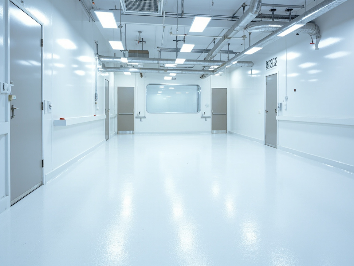
Coating is not an isolated process; it is deeply coupled with the plant systems:
- Airflow Organization: ISO Class 3–5 zones are mostly unidirectional flow (laminar flow), ceiling fully equipped with FFU, wall and ceiling coatings long-term withstand stable wind pressure and micro-vibration, requiring high adhesion and fatigue resistance; non-unidirectional flow zones focus more on dust-free maintenance under turbulent flow.
- Pressure Differential Gradient and Airtightness: adjacent rooms maintain ≥5–10 Pa positive pressure, maintained by coating and sealing at door gaps, wall-penetrating pipes, joints; if joints crack, pressure differential loses control, cross-contamination, cleanliness directly fails.
- Temperature and Humidity: semiconductor zones often control 22±1℃, 45±5% RH, coating thermal expansion coefficient must match substrate to avoid stress cracking during seasonal changes.
- Chemical Supply Surroundings: at CDU (chemical dispense unit) of acid/alkali/organic solvent and pipe wall penetration, wall must have chemical-resistant reinforcement layer to prevent leakage corrosion of structure.
These are points that "coating engineers" and "facility/process engineers" must jointly review; looking only at coating samples will miss system risks.
XI. Material Chemistry Deep Dive: Epoxy / Polyurethane / Vinyl Ester
The trade-off among three resin types determines chemical resistance and life:
- Epoxy Resin: high crosslink density, strong adhesion, excellent alkali resistance, but brittle, average weather resistance, not resistant to strong oxidizing acids; the backbone base for floors and walls.
- Polyurethane (PU): flexible, wear-resistant, weather-resistant, resistant to some solvents, suitable for high-traffic areas and joints requiring elasticity, but inferior to vinyl ester under strong acids.
- Vinyl Ester (VE): methacrylic-modified epoxy, resistant to strong acids (sulfuric, nitric), high temperature, excellent anti-permeation, first choice for wet areas and HF surroundings, but narrow application window, requires professional team.
- Conductive Filler Mechanism: anti-static relies on fillers forming conductive pathways in resin by exceeding percolation threshold, carbon black, carbon fiber, conductive zinc oxide, graphene (see graphene conductive anti-corrosion coating) each have critical addition amount and resistivity curve, excess sacrifices mechanics and appearance.
Understanding the resin-filler-medium ternary relationship balances "chemical resistance" "anti-static" "low outgassing" three goals into a specific formulation.
XII. Verification and Handover (Commissioning & Validation)
Completion of cleanroom coating does not equal qualification; must pass verification and handover:
- Particle Concentration: according to ISO 14644-1 / ISO 14644-3 static and empty-state testing, confirm grade meets standard;
- Surface Resistance Grid Map: full-area point layout measuring point-to-point resistance, draw heat map, confirm no blind spots;
- Outgassing Report: TD-GCMS screening of siloxanes and condensable volatiles, compare with wafer fab threshold;
- Physical Properties: adhesion (GB/T 9286 cross-cut), thickness, wear, impact, based on GB/T 22374-2008 "Floor Coating Materials" and GB/T 17657 type methods;
- Chemical Resistance Report: immersion data for in-plant medium list;
- IQ/OQ Documents: Installation Qualification and Operational Qualification, included in plant validation package.
Only with all above evidence complete can the coating system be signed off and counted into the cleanroom overall compliance archive.
XIII. O&M and Retrofit Key Points
- Daily Cleaning: wipe with isopropanol, hydrogen peroxide or dedicated neutral cleaner, forbid strong solvents (e.g., ketones, strong alkali) damaging topcoat and conductive network;
- Periodic Testing: quarterly measure floor static decay and resistance, repair conductive path promptly if exceed standard;
- Local Repair: at damage, grind, clean, patch with same-system material and retest, avoid incompatibility of dissimilar materials;
- Process Upgrade Recheck: when line introduces new chemical (e.g., higher concentration HF, new stripper), must recheck coating chemical resistance grade, locally upgrade to vinyl ester reinforcement if necessary.
Most overlooked in O&M is "chemical list change" — coating selection and line process are bound; if process changes, protection grade must be rechecked.
XIV. Typical Failure Case Analysis
Real accidents best illustrate the system value of coating:
- Outgassing Fog Defect: a plant cleanroom wall used silicone-containing sealant, volatilized siloxanes fogged on exposure lens, causing batch wafer yield drop, finally fully replaced silicon-free system and did TD-GCMS screening to recover.
- ESD Breakdown: floor conductive network poorly grounded, personnel walking accumulated charge, discharged when opening wafer box, single loss can reach hundreds of thousands; afterwards rebuilt grounding and testing per IEC 61340-5-1.
- HF Leakage Corrosion: wet area originally used ordinary epoxy, after months of micro-leak of hydrofluoric acid pipe, floor corroded through, rebar exposed, shutdown rework cost extremely high; recoat changed to vinyl ester reinforcement to root out.
Common point of these cases: problem not in "coating sample qualified", but in system design and O&M.
XV. Differences Between New and Retrofit Projects
- New Project: can synchronize with civil design, embed conductive grounding grid, plan cove and wall penetration sealing, high material freedom, easy to achieve optimum;
- Retrofit Project: often requires non-stop production, must zone and time-share construction, temporary positive pressure and isolation, prioritize fast-cure, low-odor systems, and must be compatible with existing coating (do adhesion and compatibility tests), higher difficulty.
Project type directly determines process sequence and risk, should be clarified at scheme stage.
XVI. Life Cycle and Total Cost of Ownership (TCO)
Coating is not the cheaper the better. The service life of cleanroom floors is often required to be 10–15 years. If premature failure occurs due to insufficient chemical resistance, the losses from production stoppage and rework far exceed the material price difference. TCO should include: material cost, construction cost, production stoppage loss, testing and certification fees, and operation and maintenance cost. For high-grade zones, select vinyl ester and silicon-free anti-static systems; the unit cost is higher but the benefits in service life and yield are significant, and from the perspective of overall plant economy it is often the better choice.
17. Summary of Standards and Acceptance Checklist
For quick engineering verification: ISO 14644-1/3 (classification and testing), GB 50073 (cleanroom design), ANSI/ESD S20.20 and IEC 61340-5-1 (ESD), GB 30981-2020 (VOC), GB/T 22374-2008 (floor materials), GB/T 9286 (adhesion), GB/T 9274 (chemical resistance), GB/T 2423 series (environment). Confirm item by item according to this checklist to turn "cleanroom coating" from an experience-based task into an auditable engineering process.
18. Detailed Explanation of Layered Structure and Grounding Design of Anti-static Floors
Anti-static epoxy self-leveling is not "pour down a bucket of material", but a bottom-up functional layered system, where each layer has a clear responsibility:
| Structural Layer | Typical Practice | Functional Responsibility | Key Control Points |
|---|---|---|---|
| Concrete Substrate | Moisture content <4%, strength up to standard | Load bearing and base leveling | Moisture content, hollowing, crack repair |
| Penetrating Primer | Low-viscosity epoxy sealing | Seal capillary pores, enhance adhesion | Sufficient penetration, no missed coating |
| Conductive Primer | Epoxy layer with conductive filler | Build horizontal conductive plane | Resistance continuity spot check |
| Grounding Grid | Copper foil tape laid by zone | Lead charges to grounding terminal | Grid spacing, overlap with conductive primer |
| Anti-static Topcoat | Conductive filler self-leveling 2–4 mm | Wear resistance, chemical resistance, vertical conductivity | Surface resistance within design range |
There are three key points in grounding design: First, the spacing of the copper foil grid and the area covered by each grounding outlet point shall be implemented according to the design document, and reliably connected to the plant's equipotential bonding terminal; the location of grounding outlets shall avoid equipment foundations and expansion joints. Second, the vertical conductive path relies on the percolation network of the topcoat filler; excessive topcoat thickness or filler settlement can cause the hidden defect of "surface qualified but system resistance exceeding limit", therefore acceptance must simultaneously measure "point-to-point resistance" and "point-to-grounding-system resistance" (according to the floor material test methods of IEC 61340-4-1 / ANSI/ESD STM7.1). Third, expansion joints and construction division joints will cut off the conductive plane; both sides of the joint shall be separately provided with grounding outlets or bridged with conductive sealant, which is the detail most easily missed during drawing review.
During daily operation and maintenance, the floor resistance will drift with waxing, cleaner residue, and surface wear. The use of ordinary insulating floor wax is prohibited; cleaner selection shall be confirmed by the supplier to not form a film on the surface; worn areas must be re-measured for zone resistance after re-coating and the resistance grid map updated, so that the "heat map" always reflects the true state.
19. Selection Decision Tree: From Process List to Coating Zoning Map
The correct starting point for cleanroom coating selection is not the coating catalog, but two lists from the process department: the cleanliness zoning map and the chemical media list. Based on this, a five-step decision tree can be followed:
- Divide coating zones by cleanliness grade: ISO Class 3–5 zones shall all adopt silicon-free, low outgassing, solvent-free systems, and reserve outgassing screening; ISO 6–7 zones may be moderately relaxed, but silicon-containing additives are still prohibited.
- Divide chemical resistance grade by media list: For wet zones with HF or hot concentrated acid, around CDU, and waste liquid trenches, specify vinyl ester reinforcement layer and prohibit silicon fillers; for areas with only alkali, developer, and IPA, solvent-free epoxy can cover.
- Divide ESD zones by personnel and equipment flow: Floor in personnel operation areas shall be static dissipative grade (10⁶–10⁹ Ω); AGV and forklift aisles shall add wear resistance consideration and select polyurethane mortar or thickened epoxy; ordinary auxiliary area walls only need anti-static grade.
- Divide physical grade by load and temperature: Areas with steam cleaning or temperature shock select polyurethane mortar (better temperature variation resistance than epoxy); heavy load areas increase thickness and compressive grade.
- Cross-check and output coating zoning map: Overlay the above four judgments, output a zoning drawing marked with "system + thickness + resistance range + chemical resistance grade", as the common basis for bidding and acceptance.
The value of this decision tree is to shift selection from "selecting a product" to "compiling a zoning map". The needs of various zones in a wafer fab differ greatly; using one material for the whole plant either over-designs and wastes budget, or under-protects and buries stoppage risks.
20. Construction Organization: Zoned Operation Management for Non-stop Modification
For coating modification in an in-production wafer fab, construction organization tests skill more than the material itself. The core principle is "isolation, positive pressure, fast curing, reversible":
Isolation and Differential Pressure Management: The construction zone is enclosed with fireproof barriers and double-layer curtains, with independent temporary exhaust and maintained negative pressure relative to the clean zone (to prevent dust escape), while ensuring the differential pressure gradient of adjacent production zones is not disrupted; all grinding processes use vacuum-equipped equipment to collect dust at source.
Timing and Windows: Use production line maintenance windows to arrange high-dust and high-odor processes such as grinding and priming; select fast-curing systems for topcoat construction to shorten occupation time; after each zone is completed, self-check particles and resistance first, and only dismantle isolation and merge into the clean zone when qualified, forming a rolling cycle of "construction—testing—release".
Personnel and Material Management: Construction personnel change clothes and air shower according to cleanroom procedures, material barrels are wiped to remove dust before entering; construction tools are dedicated to the zone to avoid bringing pollutants from ordinary sites.
Emergency and Reversal Plan: Predefine how to pause and restore isolation if odor or particles exceed limits; compatibility tests between rework materials and existing coating shall be completed in advance to avoid trial-and-error during construction. The price difference in modification projects often lies in these management actions; a team that wins the low bid but lacks clean construction capability ultimately pays with a production line contamination accident.
Kexin New Materials (kexinMaterials) experience in modification projects is: the material scheme and construction organization scheme must be reviewed and disclosed together; the supplier shall provide zoned construction guidance and on-site technical representatives, rather than delivering materials to the site and leaving—the deliverable of cleanroom coating is "qualified zoned test data", not "painted floor".
21. How to Read Outgassing Tests: From Report to Decision
When receiving a coating outgassing report, engineers should focus on four things. First, look at the method: thermal desorption-GC/MS (TD-GCMS) is the mainstream industry screening method; the report must state the desorption temperature and time conditions—outgassing amounts under different temperature conditions cannot be directly compared horizontally; comparison must be under the same method conditions. Second, look at species rather than just total amount: two samples with the same total volatiles may have vastly different risks—samples containing siloxanes (D3–D6 cyclic siloxanes, etc.) and condensable high-boiling substances are "veto-level" risks for lithography zones, while small amounts of low-boiling alcohols have much lower risk grades; the report should give species-classified spectra and quantification, not a vague total outgassing number. Third, look at the state: whether the sample is prepared according to actual construction ratio and curing regime; laboratory over-baked samples will "beautify" data, so must require stating curing conditions and preferably send for testing with the same curing age as the site. Fourth, look at the trend: one-time data only represents that batch; mass production supply should agree on batch or periodic re-testing, incorporating outgassing into the incoming inspection protocol to prevent risk drift from "silent changes" in formula or additives.
For wafer fabs, a more prudent approach is to write outgassing thresholds into the procurement technical agreement: define test method, list of judgment species and limits, testing frequency and non-conformance handling process, making "low outgassing" from a slogan into an executable and accountable contract clause. Coating material is only one link in the cleanroom contamination control chain, but due to its huge area and high replacement cost, once wrongly selected it becomes a long-term pollution source; building a solid outgassing evidence chain upfront is the risk control action with the highest ROI. At the same time, sealants, cove strips, expansion joint fillers—these "supporting materials" should also be included in the same outgassing and silicon-free review—in practice, many haze defect accidents originate from ignored auxiliary materials rather than the main coating itself; the review list must cover every organic material entering the clean space.
FAQ
FAQ
Q: Why do semiconductor cleanrooms emphasize "silicon-free" coatings?
A: Siloxanes (such as organosilicon) easily volatilize and form contamination on wafer surfaces or exposure lenses, causing haze defects and yield decline. Cleanroom coatings must be free of silicone oil and silicone leveling agents, and undergo outgassing screening on incoming materials.
Q: What surface resistance is qualified for cleanroom floors?
A: Anti-static floors typically require surface resistance 10⁶–10⁹ Ω (point-to-point, system resistance), and reliable grounding, based on the overall link evaluation of ANSI/ESD S20.20 and IEC 61340-5-1, rather than measuring a single point.
Q: What is the concept of ISO Class 5?
A: According to ISO 14644-1, ISO Class 5 means the number of particles ≥0.1 µm per cubic meter of air shall not exceed about 3.52×10⁶ (old standard approx. Class 100), a common grade for semiconductor front-end, with extremely high requirements for non-dust-generating and low-outgassing coating.
Q: What coating should be used in hydrofluoric acid zones?
A: The F⁻ of HF attacks silicon-containing materials; ordinary epoxy and silicon fillers are not applicable. Modified vinyl ester or specialized HF-resistant resin should be selected, and silicon fillers avoided; specifically based on immersion test reports targeting HF.
Q: Can ordinary epoxy floor be directly used in cleanrooms?
A: Ordinary solvent-based epoxy outgasses, may contain silicon, and has poor conductivity, generally not meeting semiconductor cleanroom requirements. Must switch to solvent-free, silicon-free, anti-static, chemical-resistant specialized systems.
Q: Do both walls and floors need to be anti-static?
A:The floor is the main surface for static electricity generation and dissipation by personnel/equipment, and must be anti-static (10⁶–10⁹ Ω); walls are mostly static-dissipative (10⁹–10¹¹ Ω) to suppress dust adhesion, and are set up in grades.
Q: What is the use of cove radius?
A: Making R≥30 mm cove radius at wall-floor and wall-ceiling junctions eliminates right-angle dust accumulation dead corners and facilitates wiping and disinfection. It is a standard practice in cleanroom coating and is critical for maintaining particle control.
Q: How to control VOC during construction?
A: According to GB 30981-2020, select 100% solid-content solvent-free or water-based systems, maintain temporary positive pressure and ventilation in the construction area, and use low-migration materials, which protects construction personnel and reduces later outgassing risk.
Q: How often should the coating be tested for static electricity?
A: It is recommended to regularly (e.g., quarterly) use a surface resistance meter (ANSI/ESD STM11.11 method) to test floor resistance and decay per the maintenance plan, and promptly repair the conductive path if exceeding limits.
Q: Can cleanroom coating be refurbished by ourselves?
A: Local repair can be done in non-stop production areas, but overall refurbishment requires controlled environment, dust-free construction, and retesting of particles and resistance. Cross-media (e.g., adding HF process) must re-verify the chemical resistance grade.
Further Reading
- Electronic Conformal Nano Coating: Principle of Ultra-thin Protective Film and Electronic Protection Applications
- Graphene Conductive Anti-corrosion Coating: Analysis of Flake Shielding and Conductive Mechanism
- Interpretation of VOC Limit Regulations for Industrial Protective Coating (ind-voc-regulation)
- Weather-resistant Anti-corrosion Coating for Photovoltaic Supports: Coating Assurance for 25-year Outdoor Service Life
- Outdoor Weather-resistant Coating for Charging Piles: Long-term Protection System for Charging Facility Enclosures
- Overview of Nano Coating: Nano Particles, Mechanism of Action and Definition Boundaries