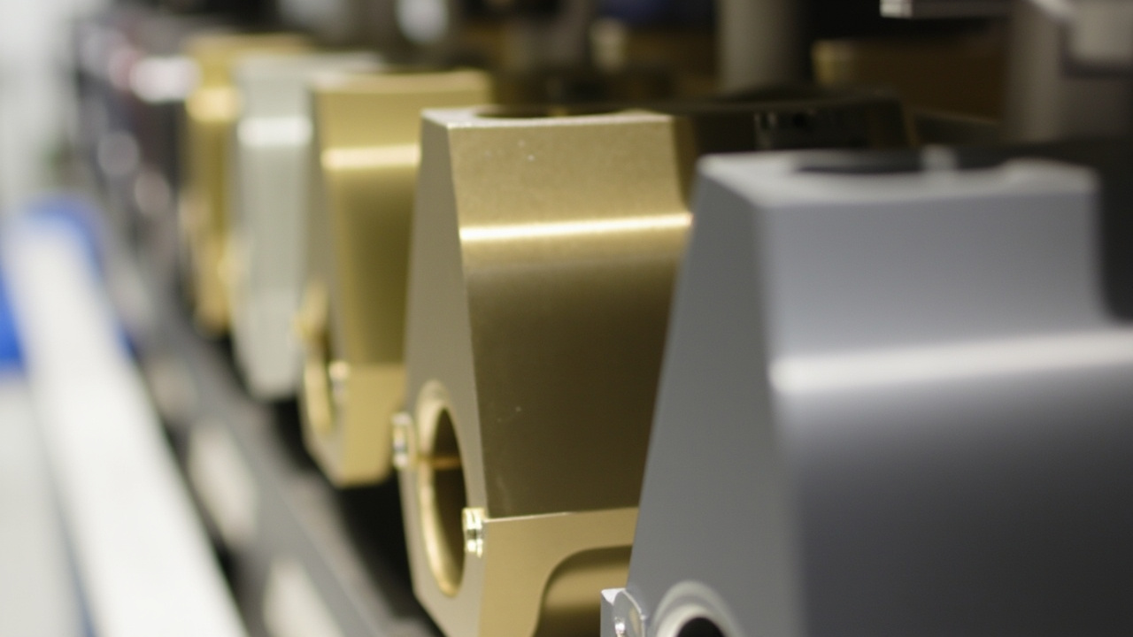
A metallic bipolar plate (BP) is the thin metal component inside a proton exchange membrane fuel cell (PEMFC) stack that simultaneously collects current at the anode and the cathode, separates the two gas chambers, and distributes the reactant gases while carrying out water and heat management; it is typically stamped from 316L stainless steel, titanium or aluminium sheet 0.08 mm–0.20 mm thick into flow-field plates and stacked face to face in pairs. Its surface must carry an anti-corrosion coating that conducts and passivates at the same time, and engineering acceptance of that coating rests on two axes: interfacial contact resistance (ICR, in mΩ·cm²) and corrosion current density (icorr, in μA/cm²).
1. A failure scenario: the membrane survives, the stack fades first
In vehicular hydrogen fuel cell stacks, power fade is often not the catalyst failing first but the plate interface turning "dirty". Inside a cavity that is acidic (pH around 3), carries trace fluoride (of the order of 0.1 × 10⁻⁶ HF), runs at 60 ℃–80 ℃ and sits under an applied potential, a bare metal surface or one with incomplete coating coverage dissolves anodically without ever stopping. The Fe, Cr and Ni ions released migrate into the membrane electrode assembly and occupy the sulphonate sites of the proton exchange membrane, degrading its conductivity and water retention; at the same time, on the mating face between the plate and the gas diffusion layer (GDL), corrosion products pile up as hydroxides/oxides into a loose, poorly conducting interlayer that drags an interface resistance of a few mΩ·cm² steadily upwards. The stack shows voltage sag at constant current and rising internal resistance, and this fade is irreversible — neither cleaning nor reassembly brings back metal that has already dissolved away.
Published research makes the scale of this chain explicit: uncoated 316L stainless steel reaches corrosion current densities of the order of 26 μA/cm² in simulated cathode environments, while a Nb-doped TiO₂ coating pulls that down to 0.13 μA/cm² (0.1 mol/L H₂SO₄, 80 ℃); a bare titanium plate sits at about 36.02 μA/cm², which a composite coating reduces to 1.41 μA/cm². The same body of literature also records counter-examples: a conducting-polymer coating still showed a corrosion current density of 9.25 μA/cm² in 0.1 mol/L H₂SO₄, with a bulk conductivity of only 13.17 S/cm — an order of magnitude away from the DOE target of >100 S/cm for bipolar plate materials. In other words, "does this coating stop corrosion" and "does this coating conduct" are two sides of one coin, and data that report only one side have no acceptance value.
The TL;DR below lays out the acceptance criteria used in this article up front; the detail and the sources are expanded item by item in the sections that follow.
- The DOE 2025 technology targets for metallic bipolar plates (as cited in published reviews) are: corrosion current density ≤1 μA/cm²; ICR ≤10 mΩ·cm² @1.4 MPa; conductivity >100 S/cm; component cost 5000 h (pH=3 H₂SO₄ + 0.1 × 10⁻⁶ HF, 80 ℃).
- The current Chinese test standard is GB/T 20042.6-2024 "Proton exchange membrane fuel cells — Part 6: Test methods for bipolar plate characteristics", issued 2024-03-15 and implemented 2024-10-01, replacing GB/T 20042.6-2011; it makes coating thickness, coating adhesion strength and the composition and concentration of leached ions separate test items.
- ICR must always be reported together with the clamping pressure: published CrN coatings read 8.4 mΩ·cm² at 100 N/cm², while a-C-based coatings reach as low as 0.87 mΩ·cm² at 1.4 MPa; the same material can read more than 2 times differently at 0.6 MPa than at 1.4 MPa, so an ICR figure quoted without pressure is worth nothing.
- Half of the drive towards chrome-free processing comes from regulation: on 2025-04-29 the ECHA published its Cr(VI) restriction proposal, planning to move the relevant substances from REACH Annex XIV (the Authorisation List — chromium trioxide and chromic acid sit at entries 16/17, with a review date of 2017-09-21) to Annex XVII (the Restriction List); the occupational exposure values under discussion are 8-hour time-weighted 0.1 μg/m³–5 μg/m³, with an 18-month transition period.
- Neutral salt spray cannot serve on its own as an acceptance test for coated plates: the NSS conditions of ISO 9227 and GB/T 10125-2021 are (50±5) g/L NaCl, pH 6.5–7.2, (35±2) ℃ — no applied potential, no fluoride ions, and a different failure mechanism from the stack cavity; the standards themselves state that salt-spray results should not be extrapolated directly into long-term corrosion life in real service.
- Formability is a quantifiable criterion rather than workshop intuition: a CrN coating of the order of 50 nm retained both its corrosion resistance and its conduction after severe deformation of 20% in x and 5% in y, showing that "coat first, stamp second" is feasible in specific systems; by contrast, columnar monolayer films crack more readily at the channel roots.
- The production side already offers public reference figures: one Chinese coating production line disclosed that single-furnace PVD output rose from tens of plates per day in 2017 to 4,000 plates per day on the line commissioned in 2026, with annual capacity above 1.2 million plates and a claimed yield of 99.9%.
2. Why the duty is harsher than ordinary anticorrosion systems
Conventional heavy-duty coatings on steel structures — whether epoxy glass-flake systems or polyurethane topcoats — answer one question: "in atmospheric, immersed or chemical exposure, can the coating keep the medium away from the substrate?" A bipolar plate coating must answer four questions at once: does it hold back the acid and the fluoride, does it carry the current, does it survive the assembly clamp pressure and the stamping strain, and do the ions it releases poison the membrane electrode assembly. The "insulating means safe" logic of the first world is precisely fatal here — the denser and more insulating the coating, the higher the ICR and the greater the stack efficiency loss.
2.1 Acid plus fluoride: why the passive film cannot hold
Stainless steel relies on a chromium-rich oxide film only nanometres thick, and the PEMFC cavity contains two things aimed squarely at it: a dilute sulphuric acid environment at around pH 3, and trace fluoride ions from the degradation products of the perfluorosulphonic acid (PFSA) membrane. Fluoride destroys the oxide by coordination dissolution, pulling Cr³⁺/Fe³⁺ out of the film as soluble fluoro-complexes so the passive layer can never heal itself. The simulated solutions widely adopted in the literature show the design intent clearly: 0.5 mol/L H₂SO₄ + 2 × 10⁻⁶ HF, 0.5 mol/L H₂SO₄ + 5 × 10⁻⁶ HF, 0.05 mol/L H₂SO₄ + 2 ppm NaF, and the DOE formulation of pH=3 H₂SO₄ + 0.1 × 10⁻⁶ HF, with test temperatures clustered at 60 ℃, 70 ℃ and 80 ℃. A single comparison explains why "no red rust" in a salt-spray cabinet is not comparable evidence: NSS uses a fluoride-free neutral chloride solution.
2.2 The potential window: 0.67 V and 1.43 V are the two fault lines
The plate never sits at open circuit. The cathode side operates at 0.6 V–0.9 V (vs SHE), the anode side approaches the hydrogen-evolution potential, and start-up/shut-down (SU/SD) and transient events can push local potentials higher still. Published work on C/Ti/316L composite coatings provides a very practical contrast: under potentiostatic polarisation at 0.67 V the coating kept the corrosion current density inside 0.5 μA/cm² even at 90 ℃ and held ICR below 2 mΩ·cm²; raise the polarisation potential to 1.43 V with elevated temperature, and a chain reaction sets in — preferential corrosion of the carbon, exposure and dissolution of the titanium interlayer, formation and dissolution of titanium oxides — and the through-thickness conductivity degrades with it. The engineering conclusion: carbon-based coatings must be selected against the actual potential ceiling, not the average working potential, above all in heavy-duty vehicles that start and stop frequently.
3. ICR: definition, measurement protocol, and measuring before and after ageing
Interfacial contact resistance is the contact resistance per unit area between the plate and the GDL (or carbon composite layer) under a stated clamping pressure, with the dimension mΩ·cm². It is not a bulk property of the material: the same plate can read entirely differently depending on polished versus rough surfaces, flatness inside or outside tolerance, channel crest versus channel floor. GB/T 20042.6-2024 devotes a standalone chapter to "contact resistance test of bipolar plate components" while retaining the geometric items — flatness, relative flatness, thickness uniformity, channel-depth uniformity, area utilisation — and the logic is exactly this: ICR scatter is usually contributed first by geometry and assembly, and only then by the coating.
The third-party reading of the standard apparatus parameters is: gold-plated copper electrodes, contact area 5 cm², test pressure 1.5 MPa, current density 40 mA/cm², with the bulk resistance removed by the two-specimen formula R=(R₁−R₂)×S/2, in an environment controlled to 25±2 ℃ and humidity ≤65%. This reading comes from a public web interpretation rather than the standard text itself; procurement should rely on the official document and the laboratory's raw records. It is quoted here to make the point that a report must state four things: pressure, area, current, and whether the bulk resistance was subtracted.
| Metric | Unit and protocol | DOE 2025 target (as cited in reviews) | Published measured samples | Industry-published figures (not independently re-tested) |
|---|---|---|---|---|
| Corrosion current density icorr | μA/cm², pH=3 H₂SO₄ + 0.1 × 10⁻⁶ HF, 80 ℃ | ≤1 | Nb-Cr-C/Ti 0.022 (cathode); a-C/TA1 3.37 × 10⁻³; TiN/Ti 0.278 | 4.5 × 10⁻⁸ A/cm², i.e. 0.045 μA/cm² (0.84 V vs SHE, 80 ℃) |
| Interfacial contact resistance ICR | mΩ·cm², clamping pressure must be stated | ≤10 @1.4 MPa | a-C/Ag/Cr 0.87 @1.4 MPa; Nb-Cr-C 1.15 @1.5 MPa; CrN 8.4 @100 N/cm² | 1.5 @1.4 MPa; 3.5 @0.6 MPa |
| Conductivity | S/cm (material bulk) | >100 | Conducting polymer SGO₃/PPy at 13.17, target missed | No specific value published |
| Component cost | $/kW | <2 | Precious-metal routes (Au/Pt/Ag) struggle to cover this band | Non-precious multilayer systems taken as the benchmark direction |
| Durability | h (short stack/bench) | >5000 | 3 h–720 h potentiostatic, 30 d immersion, 300 h single-cell polarisation — mostly fragmentary data | Bench 5000 h with performance decay ≤3%; design life >20000 h; over 200,000 km road-tested per vehicle |
| Geometry and assembly | mm, MPa, % | — (constrained by the component standards) | Composite plate moulded channels 0.65 mm deep, 0.5 mm wide | Clamping pressure 0.6 MPa–1.4 MPa is the commonly quoted band |
3.1 Why "ICR increase after ageing" belongs in the acceptance clause
A low initial ICR only says the coating conducts right now; it makes no promise about what is left after 5000 h. Research on Cr coatings gives a typical contrast: a dense CrO* surface layer formed by oxygen-plasma treatment started with a higher ICR than the untreated CrOn/Cr, yet after 3 h at +0.6 V potentiostatic in 0.05 mol/L H₂SO₄ + 2 ppm NaF its ICR increase was clearly smaller, because the dense top layer suppressed further oxidation and the build-up of corrosion products. Translated into contract language: the acceptance metric should be "initial value ≤X and increase after ageing ≤Y%"; a test report that gives only the initial value has no discriminating power here.
3.2 Clamping pressure, gaskets and the pressure distribution over the GDL
When the stack is closed up, the end-plate load comes down through gaskets, frames and channel crests one line at a time, and the actual pressure distribution is never a uniform 1.4 MPa. The common pattern: lower pressure in the gasket rebound zones (0.3 MPa–0.8 MPa), higher pressure where the channel crests meet the frame (up to more than 1.5 times the nominal value). Two consequences follow: in the low-pressure zones the real contact area is insufficient and ICR rises locally; in the high-pressure zones the coating is pressed between the carbon fibres of the GDL, asperity shear thins the film and can even wear it through. A coating specification therefore has to treat pressure, contact area and film thickness as three coupled variables — a single point measurement cannot be extrapolated to the whole plate.
4. The chrome-free route: regulatory pressure, mechanism risk, and four technical paths
In the bipolar plate context, "chrome-free" means two different things that must be stated separately: first, banning hexavalent-chromium conversion coatings and passivation baths (a regulatory and occupational-exposure issue); second, avoiding as far as possible the further oxidation of chromium-bearing coatings into high-valent chromium species under cathodic potential (a mechanism and leached-ion issue). Neither is as simple as changing a grade.
The regulatory timeline is a matter of public record. Chromium trioxide and chromic acid sit at entries 16/17 of REACH Annex XIV with a review date of 2017-09-21, and several chromates (including bichromate and trichromate type compounds and basic zinc strontium chromate) expired on 2019-01-22; in Case C-144/21 the Court of Justice of the European Union partly annulled the 2020 upstream authorisation decision, triggering a surge of authorisation applications — according to the statistics of 2023-09-18, 273 of the 518 SVHC uses identified in authorisation reports (about 53%) concerned hexavalent chromium. The European Commission therefore mandated ECHA on 2023-10-11 to draft an Annex XV restriction report, which ECHA published on 2025-04-29: the three options under discussion (RO1/RO2/RO3) correspond to 8-hour time-weighted occupational exposure values of 1 μg/m³–5 μg/m³, 0.5 μg/m³–1 μg/m³ and 0.1 μg/m³–0.5 μg/m³ respectively, air and water emissions falling in the bands of 0.025 kg/yr–2.5 kg/yr and 0.15 kg/yr–15 kg/yr, with a uniform 18-month transition; ECHA estimates that full implementation would cut about 17 t of Cr(VI) emissions per year, with net benefits of roughly EUR 331 million to EUR 1.07 billion over 20 years against social costs of about EUR 314 million to EUR 3.23 billion.
The mechanism-side risk is equally backed by measurement. Cr coatings continue to oxidise at normal PEMFC cathode working potentials (0.6 V–0.9 V): XPS depth profiling shows chromium in the surface oxide reaching its highest oxidation state, hexavalent Cr(VI); if that oxide layer is porous and poorly conducting, it shows up directly as ICR climbing. GB/T 20042.6-2024 lists "test for composition and concentration of leached ions" as a component test precisely so that buyers can quantify this migration risk at incoming inspection, instead of tracing backwards after membrane-electrode poisoning appears in the field.
4.1 Making the pre-treatment chrome-free first: the realistic options in passivation and conversion coatings
Many teams focus on the topcoat or the PVD layer while the pre-treatment is still chromate. The chrome-free path for stainless steel has long been standardised: ASTM A967 covers both nitric and citric acid passivation recipes; QQ-P-35C, the military specification that once held this position alone, was cancelled in 1998, and the aerospace AMS-QQ-P-35 was replaced in 2005 by SAE AMS2700, which allows a choice between citric and nitric acid. Published technical literature provides a set of very useful contrasts: after citric passivation the ESCA chromium-oxide/iron-oxide ratio was 5.3–5.5 versus 2.0–2.1 for the nitric route; AES depth profiling gave oxide film thicknesses of 27.0 Å–28.0 Å versus 17.0 Å–21.0 Å. Metal analysis of a citric acid bath after 30 days of continuous use showed Fe at 0.72 mg/L while Ni and Cr both stayed below 0.05 mg/L, evidence that it strips free iron selectively while barely dissolving the alloying elements of the substrate. Austenitic grades commonly run a bath at pH around 2, while martensitic and precipitation-hardening grades are advised at pH ≥3; validity can be verified by public methods such as the copper sulphate spot test, boiling distilled water, damp heat, or salt spray. Within the coatings industry, zinc-dust systems completed the chrome-free transition much earlier; the engineering experience of moving from chromate sealing to chrome-free sealing and nano-Dacromet routes (including how to handle residual corrosion resistance and hydrogen-embrittlement risk) is set out in Ultrathin high-corrosion-resistance nano-Dacromet coatings for fasteners: surface engineering from the chrome-free transition to high-strength fasteners.
4.2 Nitrides and carbonitrides: the compromise band between conduction and corrosion resistance
The cross-section morphology decides where this family of films is weak: the columnar grains grown by physical vapour deposition leave straight-through corridors between the columns, and corrosion media migrate along column boundaries far faster than through the grains — which is why multilayer architectures (inserting oxide interfaces between layers to interrupt columnar growth) recur throughout the published research.

The published measurements of this family put the "compromise" on a quantitative footing. Nanostructured TiN prepared by HiPIMS on titanium reached icorr of 0.278 μA/cm² in 0.5 mol/L H₂SO₄ + 2 × 10⁻⁶ HF at 70 ℃, with ICR of 3.51 mΩ·cm² at 140 N/cm²; reactive magnetron sputtered 50 nm CrN on 316L came in at about 0.1 μA/cm² in 0.6 mol/L H₂SO₄ at 60 ℃ and 0.48 V vs SCE, with ICR of 8.4 mΩ·cm² at 100 N/cm², and still kept its performance after severe deformation; CFUMSIP TiCN on 316L (performing better at an acetylene flow of 2 sccm) pushed icorr down to 5.08 × 10⁻² μA/cm² but returned 10 mΩ·cm² of ICR — a typical case of corrosion resistance in surplus and conductivity under strain; CrAlCN uses carbon doping to lower the cation-vacancy concentration in the passive film, and the C-8 sccm sample gave icorr of 2.10 × 10⁻² μA/cm² at 227 mV with ICR of 2.94 mΩ·cm² at 140 N/cm². The niobium route (β-Nb₂N on 430F at 0.037 μA/cm² and 3.8 mΩ·cm²; Nb-Cr-C 500 nm on titanium at 0.022 μA/cm² as cathode, −0.051 μA/cm² as anode, and 1.15 mΩ·cm² at 1.5 MPa) points towards dense conducting phases beyond chromium, and published work shows Nb/Ta multilayers can also hold icorr inside 1.0 μA/cm².
4.3 Carbon-based and 2D materials: the sp²/sp³ ratio is the master variable
Conduction in amorphous carbon (a-C) comes from sp² clustering, while corrosion resistance and density come from sp³ bonding, so what the process really tunes is that ratio. The published data make the point: a-C deposited by arc ion plating on TA1 titanium foil (deposition rate above 100 nm/min) reached ICR of 1.125 mΩ·cm² at 1.4 MPa with icorr of about 3.37 × 10⁻³ μA/cm²; Ag/Cr co-doped a-C on 316L went as low as 0.87 mΩ·cm² at 1.4 MPa; Cr/Ti co-doped a-C gave 3.1 mΩ·cm² and 5.7 × 10⁻² μA/cm². Negative examples matter just as much: N-doped a-C on 304L helps lower ICR, but the nitrogen reduces the sp³ fraction and the film density, worsening corrosion resistance and hydrophobicity — "doping always helps" is not a valid assumption. As for vertical graphene (VG/Ti), the published report claims icorr of 0.2 μA/cm², ICR down by 2 orders of magnitude, thermal conductivity up 100 times and water contact angle increased by 68.1°, but its processing window and cost keep it closer to a laboratory result than to a production-line solution.
The platelet barrier idea runs parallel to the MXene and graphene-modified routes in the coatings industry; the mechanism side is covered in our article MXene (Ti₃C₂Tₓ) anticorrosion coatings: the platelet barrier mechanism and its engineering limits and Dispersion and engineering limits of graphene-modified barrier coatings; the dispersion and anti-settling stability of nano-fillers (which directly govern film density and pinhole density) is dealt with in Nano SiO₂ in coatings: dispersion, anti-settling, flattening and abrasion resistance.
| Route | Representative systems and thickness | Representative ICR | Representative icorr | Deformation compatibility | Main shortcoming |
|---|---|---|---|---|---|
| Metal nitrides | HiPIMS TiN (Ti-based); reactive magnetron CrN 50 nm (316L) | 3.51 mΩ·cm² @140 N/cm²; 8.4 mΩ·cm² @100 N/cm² | 0.278 μA/cm² @70 ℃; about 0.1 μA/cm² @60 ℃ | CrN retained performance after 20%/5% strain | Cr-bearing systems carry high-valent chromium and leaching risk; columnar-grain pinholes |
| Carbonitrides | CFUMSIP TiCN (316L); CrAlCN (C-8 sccm) | 10 mΩ·cm²; 2.94 mΩ·cm² @140 N/cm² | 5.08 × 10⁻² μA/cm²; 2.10 × 10⁻² μA/cm² | C doping raises density | TiCN cannot tighten conductivity and corrosion resistance at the same time |
| Niobium-based and multilayers | β-Nb₂N (430F); Nb-Cr-C 500 nm (Ti); Nb/Ta multilayer (Ti) | 3.8 mΩ·cm²; 1.15 mΩ·cm² @1.5 MPa | 0.037 μA/cm²; 0.022 μA/cm²; <1.0 μA/cm² | Multilayers interrupt columnar growth | High target and capacity cost; concentrated supply chain |
| Amorphous carbon and its doped variants | a-C (TA1, >100 nm/min); a-C/Ag/Cr and Cr/Ti co-doped a-C (316L) | 1.125 mΩ·cm²; 0.87 mΩ·cm²; 3.1 mΩ·cm² (all @1.4 MPa) | 3.37 × 10⁻³ μA/cm²; 5.7 × 10⁻² μA/cm² | High residual stress, interlayer required | Carbon corrosion at high potential and temperature; drop in sp³ worsens resistance |
| MAX phases and 2D materials | Cr₂AlC (316L, (103) orientation); vertical graphene VG (Ti) | 3.16 mΩ·cm² @1.5 MPa; 2 orders of magnitude lower than bare Ti | 0.02 μA/cm²; 0.2 μA/cm² | Self-adapting passive film | Orientation control and batch production difficulty |
| Conducting polymers | PPy/C-PDA, SGO₃/PPy (304/316); PANI/CNTs | About 35% lower than single-layer PANI | 9.25 μA/cm²; 0.18 μA/cm² (potentiodynamic) and 1.27 μA/cm² (potentiostatic); about 1.9 μA/cm² | Flexible, easy to touch up | Bulk conductivity 13.17 S/cm, still an order of magnitude below the >100 S/cm target |
5. Substrate differences: pitting and crevice corrosion on 304/316L/titanium/aluminium
A coating is not a universal patch; the substrate sets the floor of the failure. Engineers rank substrates with the pitting resistance equivalent number: PREN = w(Cr) + 3.3 × w(Mo) + 16 × w(N). Computed from the measured compositions published in the literature, 304 (18.5% Cr, 0.447% Mo, nitrogen counted at 0.05%) comes to about 20.3; a typical 316L (17% Cr, 2.25% Mo, 0.08% N) to about 26; duplex 2205 (22% Cr, 3.0% Mo, 0.17% N) to about 34. A caveat on scope: the index is an empirical quantity built for chloride pitting, and for a fluoride-bearing weak acid under applied potential it can only be used for ranking, never as an acceptance criterion.
| Substrate | Composition / estimated PREN | Pitting and crevice tendency | Conduction and interface | Forming and thickness | Other risks |
|---|---|---|---|---|---|
| 304 stainless steel | 18.5 Cr / 8.33 Ni / 0.447 Mo, PREN about 20.3 | Destabilises early in fluoride-bearing weak acid; published work shows DOE targets missed | On the bare face, a thickening passive film lifts ICR | Mature stamping, 0.10 mm gauges feasible | Depends on coating integrity; any breach becomes local corrosion |
| 316L stainless steel | 16.5–18.5 Cr / 2.0–3.0 Mo, PREN about 24–26 | More stable than 304, yet crevices still go active | Uncoated icorr can reach the order of 26 μA/cm² | High springback, narrow forming window on thin gauge | Leached Fe/Cr/Ni ions poison the membrane electrode assembly |
| Duplex 2205 | 22 Cr / 3.0 Mo / 0.17 N, PREN about 34 | Ranks high for pitting resistance; cost and supply constrained | Needs a coating system of matching grade | Narrower forming and welding windows | Published bipolar plate data still thin |
| Titanium (TA1 / Ti-6Al-4V) | — | Strong self-healing passive film, yet still dissolves on the anode side | Bare Ti reads about 36.02 μA/cm² icorr in the literature, falling to 1.41 μA/cm² with a composite coating | Foil can go as thin as 0.025 mm with little springback | Cost and hydrogen pickup; coating-substrate adhesion is the key |
| Aluminium (AA6061) and composite graphite | — | Aluminium suffers local corrosion readily in acid; graphite plates are brittle and resist fine channels | Ni-P/TiNO coated AA6061 reads 50.5 mΩ/cm² contact resistance at 1.4 MPa | Moulded composite channels commonly 0.65 mm deep, 0.5 mm wide | Galvanic risk at dissimilar-metal contacts, plus weight allocation |
5.1 Where pitting and crevice corrosion actually appear on the plate
On real hardware the corrosion morphology concentrates in three places: the channel floor (residual liquid pooling, oxygen concentration cells), the crevices where the crests overlap the gasket (pH dropping and fluoride enriching inside the gap), and the stamping burrs and shear edges (residual stress plus freshly exposed metal). All three share the same signature — stagnant medium plus an oxygen/potential gradient — which is nothing like the uniformly deposited wet film of a salt-spray cabinet, and it explains why a coating of even thickness still fails first at specific locations.
5.2 Dissimilar metals and galvanic coupling: the plate does not corrode alone
When aluminium end plates, copper busbars or stainless fasteners connect to the plate through an electrolyte-bearing path (condensate, flushing residue), the galvanic current redistributes the anode/cathode roles the coating was meant to carry. This shares its logic with coating isolation and edge sealing in mixed steel-aluminium car bodies, and the engineering practice is set out in Galvanic corrosion in steel-aluminium vehicle bodies: coating isolation, edge sealing and compatible protection design. Contact potential differences and conductive isolation layers must enter the specification table at the selection stage, not be touched up after trouble appears.
6. How stamping damages coating integrity, and the adhesion criteria
The mainstream forming routes for metallic plates are hydraulic or mechanical stamping: channel depths of 0.2 mm–0.65 mm, sheet thickness 0.08 mm–0.12 mm, and local plastic strain on the sheet that can exceed 20% at the moment of forming. Three direct consequences follow for the coating: the film thins or cracks at the channel-root radii; film and substrate debond along the channel walls and floor; and the shear edge scours the coating off entirely, leaving a band with no protection at all. In the laboratory these three defect classes rarely show up in the ICR straight away — they only reveal themselves as reading drift after hours of polarisation, once corrosion products have accumulated.

The means of judging whether the film stays put have clear anchors at the standards level. GB/T 20042.6-2024 lists "coating thickness test of bipolar plate components" and "coating adhesion strength test" as separate items, and adhesion strength is new in the 2024 edition relative to 2011 — aimed squarely at coating debonding on metallic plates. In the general coatings industry, the cross-cut method (the ISO 2409 / ASTM D3359 family) and the scratch test are both usable for screening PVD coatings, but note: PVD films are thin, far below the hundred-micrometre mark, and cross-cut grading is insensitive to them; what usually carries real discriminating power is the critical load of the scratch test and the re-measurement data after forming.
6.1 Strain, residual stress and interlayer design
One published conclusion is usable as a criterion: reactive magnetron sputtered 50 nm CrN, observed in the transmission electron microscope, kept its corrosion and conduction performance after severe deformation of 20% in x and 5% in y, demonstrating that "coat first, stamp second" is process-feasible for this class of coating. The opposing failure mode comes from internal stress: amorphous carbon films typically carry high compressive stress, and as thickness grows so does the risk of spalling and lifting, which is why production lines add Ti, Cr or Ni-P interlayers to raise film-substrate adhesion — the Ni-P/TiNO system on AA6061 is one such case, published at icorr of 0.0885 μA/cm² under cathode working voltage but still 50.5 mΩ/cm² contact resistance at 1.4 MPa: the interlayer solved adhesion without solving conduction.
6.2 Sequencing: coat-then-stamp, stamp-then-coat, and edge touch-up
The trade-off between the three routes should be decided by defect distribution. Stamp-then-coat: the film never sees deformation, but with high channel aspect ratios line-of-sight shadowing under-covers the floor and walls, and uniformity has to be recovered with planetary racks and rotating fixtures. Coat-then-stamp: coverage is even, but the coating must be given a strain budget and the die radii controlled. Local touch-up: suited to shear edges and rework, but the repair coating's conductivity, cure shrinkage and interfacial sealing must be confirmed, or a new interfacial resistance layer is introduced. On any route, incoming inspection should write "re-measure ICR and icorr after forming" into the procedure rather than qualifying flat coupons only. Where high-strength steel parts and plated layers are involved, hydrogen introduction and the outgassing window must be assessed at the same time; the relevant criteria are in Hydrogen embrittlement of high-strength fasteners and the outgassing window: criteria for plated and coated systems.
7. Corrosion validation: why salt spray alone proves nothing
The value of the salt-spray test lies in speed, comparability and quality control — not in predicting life. ISO 9227 and its Chinese identical adoption GB/T 10125-2021 define neutral salt spray (NSS) at (50±5) g/L sodium chloride solution, pH 6.5–7.2, (35±2) ℃, with a fallout rate of 1–2 mL/(80 cm²·h); acetic acid salt spray (AASS) adds glacial acetic acid to bring the pH to 3.1–3.3; copper-accelerated acetic acid salt spray (CASS) further adds copper chloride and raises the temperature to (50±2) ℃ at pH 3.0–3.1. ASTM B117-20 uses 5% (mass fraction) sodium chloride at pH 6.5–7.2 and 35 ℃. The standard texts themselves stress that results from such accelerated tests cannot be directly extrapolated into long-term corrosion resistance in real environments — their declared role is comparison between like specimens.
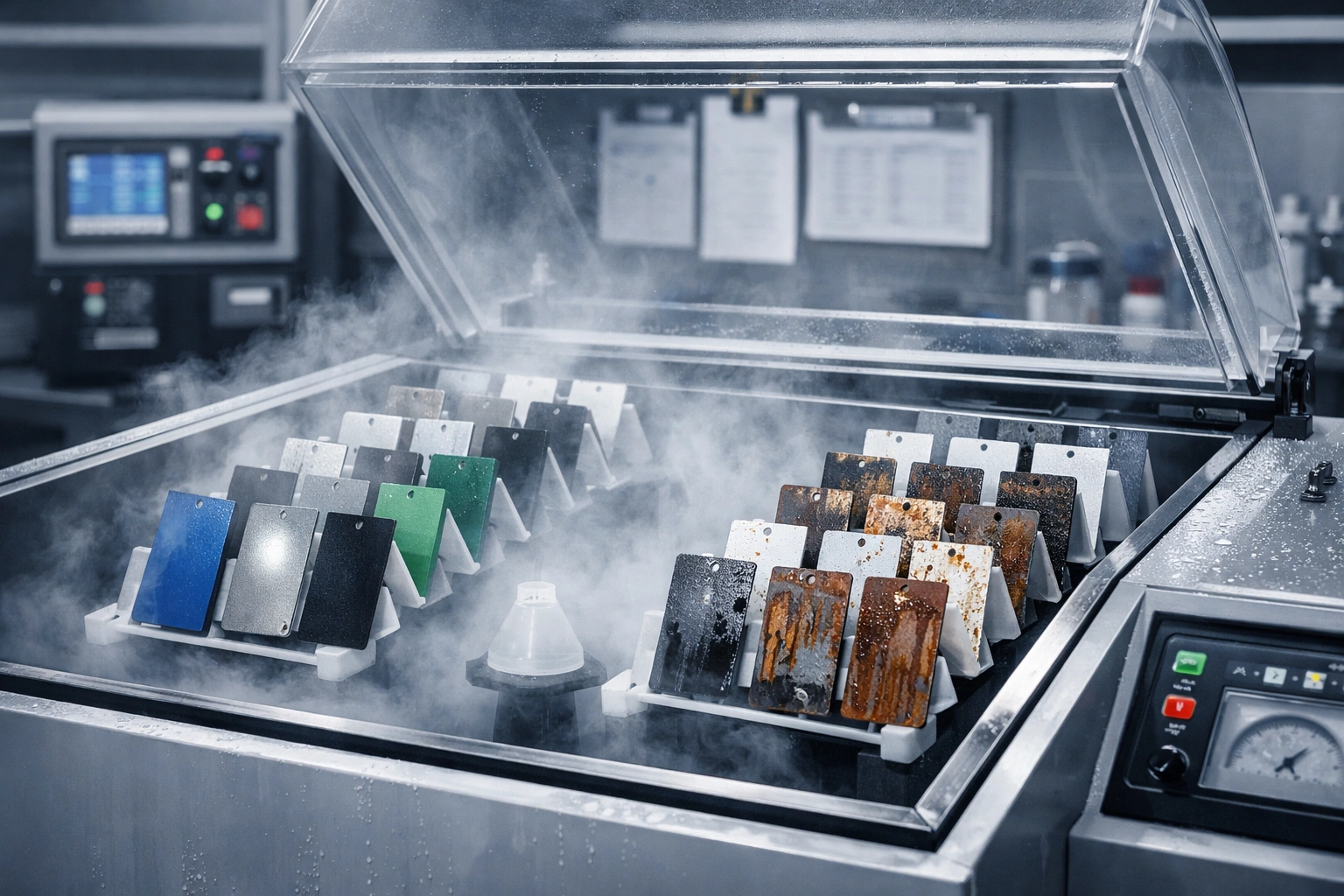
Porting salt spray onto bipolar plates misses four things. First, there is no applied potential, whereas in a stack the plate always sits in an anodically directed polarisation of 0.6 V–0.9 V, so the corrosion kinetics are completely different. Second, there is no fluoride, so the coordination dissolution of the passive film is never triggered. Third, the medium is a neutral chloride rather than pH 3 dilute sulphuric acid, and the failure morphology shifts from chloride pitting to anodic dissolution with product build-up. Fourth, salt spray does not measure conduction, and ICR is the other half of the life criterion. Conversely, icorr alone is not enough either: a conducting-polymer coating pushed corrosion current down to 0.18 μA/cm² (potentiodynamic protocol), yet its conductivity of 13.17 S/cm still fails the bar.
| Method | Typical conditions | Outputs | Can answer | Cannot answer |
|---|---|---|---|---|
| Neutral salt spray NSS (ISO 9227 / GB/T 10125-2021) | (50±5) g/L NaCl, pH 6.5–7.2, (35±2) ℃, 1–2 mL/(80 cm²·h) | Time to red rust/defects and rating | Batch consistency and early screening of barrier continuity | Life under stack potential and fluoride conditions |
| Potentiodynamic polarisation (Tafel/LSV) | 0.5 mol/L H₂SO₄ + 2 × 10⁻⁶ HF etc., 60–80 ℃ | icorr, corrosion potential | Order-of-magnitude ranking of corrosion rate | The contribution of long-term product build-up to ICR |
| Potentiostatic polarisation | +0.6 V, 0.48 V vs SCE, 0.84 V vs SHE, 1.43 V etc. | Steady-state current iss, time series | Dissolution behaviour at working and transient potentials | Real medium flow rates and temperature cycling |
| ICR re-measurement after immersion | 0.5 mol/L H₂SO₄ + 5 × 10⁻⁶ HF, 80 ℃, 3 h–30 d | ICR before/after ageing and the increase | The effect of product build-up on interfacial conduction | Local differences caused by the assembly pressure field |
| Short-stack durability and bench testing | DOE target above 5000 h; publicly reported national-standard bench at 5000 h with decay ≤3% | Polarisation-curve fade rate, per-cell voltage | System-level usability | Attribution to single-plate defects (needs teardown and re-measurement) |
7.1 A practicable combined test programme
Only by chaining these methods into one line can rate, conduction and deformation all be held at once: flat coupons for 3 h potentiostatic iss plus ICR re-measurement after 30 d immersion; stamped coupons re-measured at the same potential, the difference between the two taken as a deformation sensitivity; then coating thickness and adhesion strength per the two coating chapters of GB/T 20042.6-2024; and finally a short stack or single-cell voltage run at intermediate checkpoints of 500 h–1000 h, breaking the 5000 h target into auditable milestones. Salt spray can stay as a fast incoming-consistency screen, but it should not appear in any durability conclusion.
7.2 Three preconditions for comparable data
When comparing data across suppliers, check three things first: the medium (sulphuric acid concentration, whether the fluoride source is HF or NaF and its equivalent, temperature); the potential (whether the reference electrode is SHE or SCE, and whether the conversion is stated); and the mechanics (clamping pressure value and unit, contact area, whether the bulk resistance was subtracted). The literature carries 2 × 10⁻⁶, 5 × 10⁻⁶, 0.1 × 10⁻⁶ and 2 ppm NaF recipes side by side, and mixes N/cm² with MPa; numbers that are not aligned on these three points can differ by more than the coating systems themselves.
8. The production window: film thickness, rate, yield and cost
Between a laboratory single coupon and production batches sit four variables: deposition rate, uniformity, particle and pinhole control, and the coverage of in-line inspection. Usable public process references include three mainstream routes — magnetron sputtering (reactive sputtering and HiPIMS included), arc ion plating (including closed-field unbalanced magnetron sputtering ion plating, CFUBMSIP/CFUMSIP) and plasma-enhanced chemical vapour deposition — with film thicknesses generally falling between 50 nm and 3 μm: CrN reported at 50 nm, Nb-Cr-C at 500 nm, multilayer CrO*/Cr at about 100 nm, a-C reaching 3 μm; against a human hair of about 70 μm, these films are less than a hundredth of its diameter.
Rates and capacity are numbers that can be reconciled directly: published research used arc ion plating above 100 nm/min to prepare a-C films on TA1 titanium foil and completed batch deposition of large-area films; the industry side supplies the other set of coordinates — in 2017 a single PVD furnace produced tens of plates a day, while the non-precious-metal coating line for metallic bipolar plates commissioned in 2026 reports 4,000 plates per day, annual capacity above 1.2 million plates, a claimed yield of 99.9%, and traceable data on coating thickness, adhesion and batch consistency. These are company-published figures that have not been independently re-tested; procurement should ask for raw test records across consecutive batches rather than a single-batch report.
8.1 The thickness window: what being too thin or too thick each costs
Thickness and performance are not monotonic. On the thin side, coverage falls short and the fraction of pinhole area rises, so the steady-state current iss under potentiostatic holds tracks defect density rather than thickness — adding thickness buys little, and the fix belongs in the primer and interlayer. On the thick side, internal stress accumulates and the risk of lifting and delamination grows, while target utilisation and cycle-time cost both climb. The published a-C data give one reference landing point: films brought to the 3 μm level still held icorr and ICR inside the targets, but that reliability rests on the sp³ fraction and interlayer design, not on simply piling on thickness.
8.2 Yield, pinholes and rework
On the line, yield is usually dragged down by four defect classes: particles (chamber dust and target arcing/splash), pinholes (substrate roughness and pre-treatment residue), colour drift/thickness drift (target condition and substrate-bias drift), and edge-mask failures (fixture shadowing). The corresponding controls are incoming grading of surface roughness, fixed cleaning and drying windows, chamber pressure and residual-gas monitoring, and in-line four-point-probe or eddy-current thickness spot checks with potentiostatic batch sampling. Rework deserves caution: acid stripping before a second coating run attacks the substrate at the same time, and most systems prefer scrap to rework; where touch-up is genuinely required, confirm every one of the three touch-up questions in §6.2.
9. Key data at a glance (every line with units)
- DOE 2025 metallic bipolar plate targets (as cited in reviews): icorr ≤1 μA/cm², ICR ≤10 mΩ·cm² @1.4 MPa, conductivity >100 S/cm, cost <2 $/kW, short-stack durability >5000 h (pH=3, H₂SO₄ + 0.1 × 10⁻⁶ HF, 80 ℃).
- Published lower-bound samples: a-C/Ag/Cr (316L) ICR 0.87 mΩ·cm² @1.4 MPa; a-C/TA1 at 1.125 mΩ·cm² @1.4 MPa with icorr 3.37 × 10⁻³ μA/cm²; Nb-Cr-C 500 nm/Ti at 1.15 mΩ·cm² @1.5 MPa.
- Bare-material references: uncoated 316L icorr 26 μA/cm² (0.1 mol/L H₂SO₄, 80 ℃), reduced to 0.13 μA/cm² by a Nb-doped TiO₂ coating; bare Ti at 36.02 μA/cm², reduced to 1.41 μA/cm² by a TiN-C composite coating.
- Deformation-compatibility criterion: 50 nm CrN retained corrosion resistance and conduction after 20% strain in x and 5% in y; undeformed readings were icorr of about 0.1 μA/cm² (0.6 mol/L H₂SO₄, 60 ℃, 0.48 V vs SCE) and ICR 8.4 mΩ·cm² @100 N/cm².
- Test basis: GB/T 20042.6-2024, issued 2024-03-15 and implemented 2024-10-01, replacing the 2011 edition, contains 21 test items and adds component items such as coating adhesion strength and the composition and concentration of leached ions.
- Salt-spray comparison conditions: NSS per ISO 9227 / GB/T 10125-2021 is (50±5) g/L NaCl, pH 6.5–7.2, (35±2) ℃, fallout 1–2 mL/(80 cm²·h); CASS is (50±2) ℃, pH 3.0–3.1.
- Regulatory figures: in the Cr(VI) restriction proposal ECHA published on 2025-04-29, the occupational 8 h TWA band under discussion is 0.1 μg/m³–5 μg/m³, air emissions 0.025 kg/yr–2.5 kg/yr, water emissions 0.15 kg/yr–15 kg/yr, with an 18-month transition; of the 518 SVHC uses as of 2023-09-18, 273 involved hexavalent chromium.
- Chrome-free passivation comparison: citric passivation gives ESCA chromium-oxide/iron-oxide ratios of 5.3–5.5 versus 2.0–2.1 for nitric; AES oxide thickness 27.0 Å–28.0 Å versus 17.0 Å–21.0 Å; after 30 days, the citric bath showed Fe 0.72 mg/L with Ni and Cr both <0.05 mg/L.
- Scale references (company-published figures, not independently re-tested): production line at 4,000 plates per day, annual capacity above 1.2 million plates, claimed yield 99.9%; bipolar plates account for roughly 20% of stack cost and more than 60% of stack weight.
10. Frequently asked questions
Q1 Why can't bipolar plate coatings simply reuse a conventional heavy-duty anticorrosion system?
Because the axes of assessment differ. A conventional system aims to isolate the medium — the denser and more insulating, the better; a bipolar plate coating must hold the interfacial contact resistance inside the 10 mΩ·cm² band while still blocking corrosion (the DOE line), and it must keep leached ion concentrations controlled (GB/T 20042.6-2024 has made the composition and concentration of leached ions a component test item). A thick organic system that shows no red rust after 1000 h of salt spray is still eliminated inside the stack, simply for not conducting.
Q2 At what clamping pressure should ICR be measured? Are readings at different pressures comparable?
They are not directly comparable. The same system can read more than 2 times differently at 0.6 MPa versus 1.4 MPa (the company-published pair is 3.5 mΩ·cm² and 1.5 mΩ·cm²), and the literature mixes 100 N/cm², 140 N/cm², 1.4 MPa and 1.5 MPa conventions. The comparable practice: report the pressure value and unit, the contact area, the loading method, and whether the two-specimen bulk-resistance subtraction was used — and measure one set at the design pressure and one at ±20% of it.
Q3 Why does "ICR increase after ageing" deserve a place in the acceptance clause more than the initial ICR?
The initial value only reflects conduction at the moment of assembly, while life is governed by how fast corrosion products accumulate. The CrO*/Cr study is the textbook case: oxygen-plasma-treated samples started with a higher ICR, yet after +0.6 V polarisation for 3 h in 0.05 mol/L H₂SO₄ + 2 ppm NaF their ICR increase was clearly smaller than the untreated samples, evidence that the dense top layer suppressed sustained oxidation. Written as a clause: pass only when both "initial ≤X mΩ·cm²" and "increase after 3 h or 30 d ageing ≤Y%" hold.
Q4 Does "chrome-free coating" mean the material contains no chromium at all?
No — two layers of meaning must be separated. The first is the prohibition of hexavalent-chromium processes and substances: this belongs to REACH Annex XIV/XVII and workplace exposure management, and the ECHA restriction proposal of 2025-04-29 moves Cr(VI) from the authorisation mechanism towards restriction. The second is whether the coating chemistry contains chromium as an element: the chromium in CrN, CrAlCN and Cr₂AlC is chemically bound metallic chromium rather than a hexavalent chromium salt, yet at cathode potentials of 0.6 V–0.9 V the surface oxide can still host high-oxidation-state chromium accompanied by ion leaching. The acceptance wording therefore needs both "no hexavalent-chromium processing" and "leached ion limits", so that one vague "chrome-free" cannot paper over both.
Q5 Can 1000 h of salt spray without red rust prove 5000 h of service in the stack?
It cannot. NSS runs at (50±5) g/L NaCl, pH 6.5–7.2, (35±2) ℃, with no applied potential, no fluoride and no conductivity measurement, whereas the stack cavity imposes pH 3 dilute sulphuric acid + 0.1 × 10⁻⁶ HF, 60 ℃–80 ℃ and a cathode potential of 0.6 V–0.9 V — the drivers are not the same; ISO 9227 and GB/T 10125-2021 themselves caution that accelerated results cannot be extrapolated directly into real service life. The correct use of salt spray is as a screen for incoming consistency and film continuity; durability conclusions belong to potentiostatic polarisation, ICR re-measurement after immersion and short-stack validation.
Q6 How is cracking of the coating after stamping controlled without losing conductivity?
Four steps. Select a deformation-compatible system (published data show 50 nm CrN keeping its performance after 20%/5% strain). Use interlayers and multilayer architectures to interrupt columnar growth and relieve stress (Ni-P, Ti or Cr underlayers and (CrO*/Cr) multilayers all belong to this family). Lock the die radii and draw depths so that local strain at the channel root stays inside the qualified range. Re-measure after forming and make the ageing increase of icorr and ICR the batch-release gate. The shear edge is the exception position and must be assessed separately for touch-up or protection.
Q7 How should titanium plates be weighed against 316L plates?
Rank the decision on three lines: whether a coating is needed at all, what cost can be accepted, and whether hydrogen pickup is a concern. 316L has mature stamping and supply chains, but its uncoated corrosion current density can reach the order of 26 μA/cm², leaving it heavily dependent on coating integrity. Titanium's passive film self-heals strongly and foil can be rolled thinner; the literature value of 36.02 μA/cm² for bare Ti falls to 1.41 μA/cm² after a composite coating, and a-C/TA1 can deliver 1.125 mΩ·cm² @1.4 MPa — at the price of material cost and hydrogen management. Duplex 2205, with PREN about 34, ranks high for pitting resistance, but published bipolar plate data remain thin and should not drive the primary selection.
Q8 What datasets should incoming acceptance require at minimum?
At least five. Coating thickness and uniformity per the coating-thickness test of GB/T 20042.6-2024, with raw cross-section, ellipsometry or profilometry data attached. Coating adhesion strength (an item new in the 2024 edition of the same standard). The iss time series from potentiostatic polarisation, stating the medium recipe and the reference electrode. ICR before and after ageing, stating the clamping pressure and contact area. A report on the composition and concentration of leached ions. Add the process records of consecutive batches (chamber pressure, background, target status and bias), because a single-batch report cannot demonstrate consistency.
11. References and notes on data provenance
All data in this article derive from published standards, journal literature and openly released industry reports; no internal or customer data were used. Wherever an item is labelled "company-published figures" or "third-party interpretation", it has not been re-tested by an independent laboratory, and the formal standard text and original reports take precedence for acceptance.
- GB/T 20042.6-2024 "Proton exchange membrane fuel cells — Part 6: Test methods for bipolar plate characteristics", issued 2024-03-15, implemented 2024-10-01, replacing GB/T 20042.6-2011; ICS 27.070, CCS K82, under the National Standardization Technical Committee for Fuel Cells and Redox Flow Batteries; the current series also includes GB/T 20042.1-2017 (terms), GB/T 20042.2-2023 (general technical specifications for stacks), GB/T 20042.5-2024 (membrane electrode assemblies) and GB/T 20042.7-2024 (carbon paper).
- ISO 9227 (corrosion tests in artificial atmospheres — salt spray tests) and GB/T 10125-2021 (identical adoption); ASTM B117-20 (standard practice for operating salt spray apparatus).
- ASTM A967 (specification for chemical passivation treatments of stainless steel parts, covering the nitric and citric routes), ASTM A380 (practice for cleaning, descaling and passivation), SAE AMS2700; QQ-P-35C cancelled in 1998 and AMS-QQ-P-35 superseded by AMS2700 in 2005; the citric-versus-nitric passivation data come from the STERC public technical paper (R. Kremer, Developments in Citric Acid Passivation of Stainless Steel).
- The Cr(VI) restriction proposal published by ECHA on 2025-04-29 (RO1/RO2/RO3 options, 18-month transition, emission and exposure bands); REACH Annex XIV entries 16/17 (chromium trioxide, chromic acid, review date 2017-09-21); the partial annulment by the Court of Justice of the European Union in Case C-144/21 of the 2020 upstream authorisation decision; 273 of the 518 uses listed in the authorisation report of 2023-09-18 involving hexavalent chromium.
- Zhao Lingfang, Sun Xi, Dou Nannan, Chen Jia, Wu Zhengbin: "Research progress on coatings for metallic bipolar plates in fuel cells", Advances in Nonferrous Metal Materials and Engineering, 2025, Vol. 46 No. 4, pp. 1–9 (the DOE 2025 targets are cited therein from Liu R X et al., Int. J. Hydrogen Energy 2022, 47(54): 22915–22937, DOI:10.1016/j.ijhydene.2022.05.078).
- Coating measurement literature: DOI 10.1016/j.ijhydene.2022.09.066 (HiPIMS TiN); 10.1016/j.ijhydene.2020.03.248 (formable CrN); 10.1016/j.ijhydene.2021.06.207 (β-Nb₂N/430F); 10.1016/j.jpowsour.2021.230797 (Nb-Cr-C/Ti); 10.1016/j.corsci.2021.109757 (TiCN/316L); 10.1016/j.vacuum.2023.112084 (CrAlCN); 10.1016/j.ijhydene.2023.05.197 (a-C/TA1, >100 nm/min); 10.1016/j.carbon.2019.01.050 (a-C/Ag/Cr); 10.3390/molecules28062821 (Cr/Ti co-doped a-C); 10.1016/j.diamond.2024.111387 (a-C:N/304L); 10.1002/adma.202110565 (vertical graphene/Ti); 10.1016/j.porgcoat.2022.106995 and 10.1016/j.porgcoat.2023.107611 (conducting polymers); 10.1016/j.cej.2020.124675 (PPy/C-PDA); 10.1016/S0378-7753(01)00950-8 and 10.1016/j.jmst.2020.07.009 (precious metals and CrO*/Cr, the latter in J. Mater. Sci. Technol. 2021, 61: 75–84); 10.1177/1478422X261434419 (C/Ti/316L temperature-induced anodic dissolution); 10.1016/j.ijhydene.2009.06.030 (a-C 3 μm/316L).
- Other substrates and medium effects: Int. J. Hydrogen Energy 2012, 37: 18537–18546 (effect of pH and halides on stainless steel plate corrosion); a comparative study of Ti-6Al-4V and SUS 316L in 0.5 mol/L H₂SO₄ at 10 mV/s with 10 h potentiostatic holds.
- Industry-published report: "Fengyuan Hydrogen Energy metallic bipolar plate non-precious-metal coating production line commissioned", released 2026-09 by the Hydrogen Energy Branch of the China Industrial Development Promotion Association and trade media (4,000 plates per day, annual capacity above 1.2 million plates, claimed yield 99.9%, ICR 3.5 mΩ·cm² @0.6 MPa and 1.5 mΩ·cm² @1.4 MPa, icorr 4.5 × 10⁻⁸ A/cm² @0.84 V vs SHE in 80 ℃ pH 3 + 0.1 ppm HF, bench 5000 h with decay ≤3%, 200,000 km road testing per vehicle, bipolar plates at 20% of stack cost and more than 60% of stack weight).
- Third-party interpretations and limitations: the GB/T 20042.6-2024 apparatus parameters (gold-plated copper electrodes, 5 cm², 1.5 MPa, 40 mA/cm², R=(R₁−R₂)×S/2, 25±2 ℃ and humidity ≤65%) come from a public web interpretation, not from the standard text; PREN = w(Cr) + 3.3 × w(Mo) + 16 × w(N) is an empirical chloride-pitting index, used here for ranking only in a fluoride-bearing weak-acid system; the twenty-year net benefit of 3.31–10.7 × 10⁸ EUR and social cost of 3.14–32.3 × 10⁸ EUR cited in the text are ECHA impact-assessment bands, subject to the decisions of the European Commission and the Member States.
Last updated: 2026-11-17
Compiled by the technical team of Kexin New Materials (Guangdong) Co., Ltd., for engineering and procurement professionals in the fuel cell and industrial coatings sectors. This is B2B technical reference material and does not constitute a design basis or a performance commitment; for specific duty conditions, coating and PVD specifications must be confirmed by laboratory re-testing and bench validation data. The company's external business is industrial-grade product supply and technical support, with EXW / FOB as the trade-term basis.