
Freeze-thaw failure of coatings is the durability damage that develops in a coating and the porous concrete or mortar substrate beneath it when, in a wet condition, the system repeatedly passes through positive and sub-zero temperatures. It arises from the combined action of hydraulic pressure as pore water freezes, the growth pressure of ice and salt crystals (crystallisation pressure), and osmotic pressure from concentration differences in the pore solution. It shows as blistering, cracking, chalking and delamination of the film, usually progressing together with deterioration of the substrate surface. Three verifiable quantities decide it: the degree of water saturation of the substrate, the number of freeze-thaw cycles within a season, and whether salt-laden free liquid water is present at the surface. It is a different problem from inadequate coating water resistance, and one report cannot confirm the other.
On the deck and traffic barrier of a grade-separated interchange in northern China, map-like fine cracking and local chalking appeared in the third winter after handover. The summer ponding test had been faultless, the manufacturer's water-, alkali- and salt-spray-resistance reports were complete, and after 7 d of immersion at room temperature the ISO 4628 rating was still grade 0 to grade 1. Core sampling revealed the cause at once: the substrate moisture content ran above 6% for long periods, the cross-fall of the deck was inadequate with water pooling around the drains, and residual winter de-icing salt kept a salt-laden free liquid at the surface. The same coating batch passed completely under 23℃ constant-temperature water immersion yet lost its sealing function within two freeze-thaw seasons. The pattern recurs on northern bridge decks, tank walls, external plinths and car-park ramps, with one thing in common: design and acceptance treated water resistance as if it were freeze-thaw resistance.
TL;DR: Freeze-Thaw Coating Failure in Six Sentences
- Water resistance and freeze-thaw resistance are two yardsticks: coating-side immersion follows ISO 2812-2:2018 and ISO 2812-1:2017 and is graded 0 to 5 under the ISO 4628 series, while substrate-side follows the GB/T 50082-2009 rapid-freeze method, requiring a relative dynamic modulus of elasticity not below 60% and a mass loss not above 5%.
- The roughly 9% volume expansion of freezing water is the energy source of the damage; repeated freezing of a dry substrate causes little harm, so wetness and sub-zero temperature must coincide, which makes substrate saturation and drainage design more important than coating selection.
- De-icing salt turns internal spalling into surface scaling: the NaCl eutectic is about −21℃ at roughly 23% by mass, and the literature shows scaling depends mainly on the concentration of the surface free liquid, little on the solute type (published-data figure).
- Low-temperature qualification of the system has its own basis: the ISO 12944-9:2018 cyclic ageing includes a −20℃±2℃ cold stage, with scratch creep required below 3.0 mm for general CX areas, below 6.0 mm after seawater immersion and below 8.0 mm in high-impact zones; the ISO 12944-1:2017 durability classes L not above 7 years, M 7 to 15 years, H 15 to 25 years and VH above 25 years are only a maintenance-planning basis.
- The hard number for the low-temperature window is a substrate at least 3℃ above the dew point (ISO 8502-4 and ISO 12944-7), with a normal waterborne application floor of about 5℃, a dispersion minimum film-forming temperature (MFFT) commonly above 10℃, and a recommendation to preheat the substrate above 12℃ when the environment is below 8℃.
- Penetrant and film-forming criteria cannot be interchanged: silane impregnation under the highway specification takes a water absorption coefficient not above 0.01 mm/min^0.5, a penetration depth not less than 3 mm and a reduction in chloride uptake not less than 90% (75% in the port-water specification), and requires at least 20 more brine freeze-thaw cycles before the same mass loss than on untreated specimens.
1. Breaking Freeze-Thaw Down into Three Verifiable Quantities
Freeze-thaw damage needs three conditions to hold at once: freezable water, sub-zero temperature, and a path through which water can move in and out continuously. Remove any one and the risk drops sharply. In practice these are quantified as moisture content or degree of saturation, the number of times the daily temperature swings cross 0℃, and the ingress paths (capillary pores, micro-cracks, coating pinholes and lap joints). For the coating buyer the real decision is not which anti-freeze coating to choose but how far to push down these three factors: keep water out, let incoming water drain, or let the system tolerate the volume change of freezing. The three routes imply quite different systems and prices.
1.1 Why Passing the Water Test Is Not Passing Freeze-Thaw
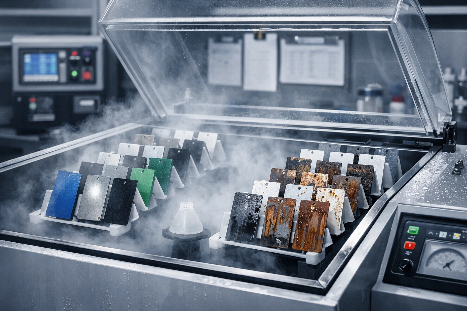
Coating-side water resistance is usually tested by immersing panels in distilled water at constant temperature under ISO 2812-2:2018 (immersion method), with ISO 2812-1:2017 used for liquids other than water; panels are conditioned at 23℃±2℃ and 50%±5% relative humidity for at least 16 h, dry film thickness is measured to ISO 2808, and the result is graded 0 to 5 for blistering, colour change and cracking under the ISO 4628 series. The substrate side uses a different yardstick. The GB/T 50082-2009 rapid-freeze method takes 100 mm×100 mm×400 mm prisms, immerses them for 4 d after 24 d of standard curing, completes each cycle within 2 h to 4 h, and measures mass and fundamental transverse frequency every 25 cycles; the frost-resistance grade is the highest cycle count that still satisfies a relative dynamic modulus of elasticity not below 60% and a mass loss not above 5%, with F50 to F300 in common use. The two probe different stresses: room-temperature immersion looks at the coating's resistance to water ingress and blistering, while freeze-thaw asks whether the system can accommodate or expel the roughly 9% volume expansion of freezing water. Repeated freezing in the dry state causes little damage; damage appears only when wetness and sub-zero temperature coincide, which is also the starting point of the critical-degree-of-saturation assumption in concrete durability design.
2. Three Mechanism Lines: Hydraulic, Osmotic and Crystallisation Pressure
Several explanations of concrete freeze-thaw coexist in the literature; three are enough for engineering. First, hydraulic pressure: as pore water begins to freeze it expands and drives unfrozen water toward warmer regions, and the flow builds pressure in narrow pore throats; when that pressure exceeds the tensile strength of the matrix, micro-cracks form (Powers' classical account). Second, osmotic pressure: once ice separates out, the remaining pore solution becomes more concentrated than an adjacent saturated zone, water is drawn in continuously, and pressure rises further. Third, crystallisation pressure: the mechanical pressure of ice or salt crystals growing against pore walls, which also explains why the damage turns into surface scaling when a salt-laden free liquid sits at the surface. The coating plays a different role on each line: against hydraulic pressure it can only reduce the water entering, not remove what has entered; against osmotic pressure its vapour permeability decides whether water vapour can escape, and over-sealing pushes the pressure back onto the interface; against crystallisation pressure, water repellency and joint sealing do more than film thickness. Blending the three into one phrase, improve coating density, is certain to misdirect selection. On the metal side add a fourth factor: the coating's elongation and cold embrittlement at sub-zero temperature decide whether corners, welds and lap joints crack or detach first.
| Mechanism | Trigger condition | Where it mainly occurs | Verifiable manifestation | What the coating can do |
|---|---|---|---|---|
| Hydraulic pressure | Pore water freezes and drives unfrozen water toward warmer zones | Concrete interior and the interfacial transition zone | Relative dynamic modulus falls with cycles, ahead of compressive strength | Reduces incoming water but cannot remove water already inside |
| Osmotic pressure | Ice separation raises the pore-solution concentration against an adjacent saturated zone | Capillary and gel pores | Local swelling, fine coating blisters, growing wet area | Keep vapour open; avoid sealing without drainage |
| Crystallisation pressure | A solute-bearing surface free liquid freezes or crystallises on the pore wall | About 5 mm to 20 mm of the surface | Surface scaling, exposed aggregate, chalking | Water repellency and joint sealing beat simply thickening the film |
| Cold embrittlement and shrinkage | Film elongation at sub-zero temperature is insufficient against substrate restraint | Corners, welds, old cracks and lap joints | Fine cracks along edges, then rust-jacking | Choose a system with enough low-temperature movement |

3. Test Criteria Compared: Coating Side and Substrate Are Not the Same Yardstick
The word freeze-thaw in reports stands for at least four quite different tests: the frost resistance of the substrate interior, the salt-frost scaling resistance of the substrate surface, the coating's own resistance to hot and cold water or to liquids, and the cyclic ageing with a cold stage that a coating system is subjected to. The specimen, cycling regime and measured quantity differ for each, and quoting their numbers side by side invites errors. The table below groups them by subject for use in design and procurement specifications.
3.1 Why Cycle Counts Cannot Be Converted Between Standards
The same 300 cycles means quite different things in different standards. In the GB/T 50082-2009 rapid-freeze method, 300 is the test ceiling, and the F300 grade is awarded only when the ceiling is reached while both the 60% and 5% criteria are still met; ASTM C666/C666M likewise uses 300 as a common endpoint, cycling from 4.4℃ down to −17.8℃ and back to 4.4℃, 2 h to 5 h per cycle, measuring the dynamic modulus every 30 cycles, but here 60% is the criterion for stopping the test, and any acceptance limit in a specification (often quoted as 80% of the initial value) must be agreed separately, so the two numbers cannot be conflated. RILEM CDF runs only 56 cycles and measures the mass of material detached per unit area together with the ultrasonic pulse velocity; single-surface freezing with a 3% NaCl solution on the face differs by an order of magnitude in damage depth from a whole specimen immersed in water and frozen from two sides. So the statement that a system passed 300 freeze-thaw cycles, without stating whether the subject is the concrete substrate or the coating, water thawing or salt frost, internal modulus or surface scaling, carries no information.
3.2 Four Things to Do First with a Test Report
- Confirm the subject first: record item by item whether the specimen is concrete, mortar or a painted steel panel, its size, and its saturation method (vacuum, two-side immersion, capillary).
- Then confirm the regime: the length of a single cycle, the end-of-freezing and end-of-thawing temperatures (core or medium), the total cycle count and the measurement interval.
- Then confirm the criteria: modulus retention, mass-loss rate, detached material or visual grade, and the threshold and stop condition for each.
- Add the coating side: whether the coating saw an independent cold stage (as in the −20℃±2℃, 24 h of ISO 12944-9:2018 cyclic ageing) and the before-and-after difference in scratch creep and pull-off adhesion.
| Standard or method | Subject | Cycling and regime | Measured quantity | Criteria note |
|---|---|---|---|---|
| GB/T 50082-2009 rapid-freeze | Ordinary concrete prisms 100 mm×100 mm×400 mm | Immersed for 4 d after 24 d standard curing; 2 h to 4 h per cycle; measured every 25 cycles | Cycle count with relative dynamic modulus not below 60% and mass loss not above 5% (F50 to F300) | Gives a grade, not a service life |
| GB/T 50082-2009 slow-freeze | Sets of cube specimens | Frozen at −15℃±2℃, thawed in water at 15℃±2℃ | Strength loss not above 25% or mass loss not above 5% (D grade) | Not convertible with the rapid-freeze method |
| ASTM C666/C666M | Rapid freezing and thawing of concrete, Procedure A water, Procedure B air | From 4.4℃ down to −17.8℃ and back to 4.4℃, 2 h to 5 h per cycle, dynamic modulus every 30 cycles | Run to 300 cycles or down to 60% of the initial value | Acceptance limit to be set separately; 80% often quoted (published-data figure) |
| ASTM C672/C672M | Horizontal surfaces with deicing chemicals | Single-sided ponding, solution commonly renewed every 5 cycles to about 50 cycles | Visual rating and amount detached (largely qualitative) | Assesses the surface only, not internal damage |
| RILEM CDF (cited in the EN 13687 series) | A 3% NaCl solution confined on the specimen face | 56 cycles | Detached mass per unit area and change in ultrasonic pulse velocity | The usual European basis for salt frost |
| ISO 2812-2:2018 / ISO 2812-1:2017 | Water and liquid resistance of painted panels | Constant-temperature immersion, conditioned at 23℃±2℃, 50%±5% RH, at least 16 h | ISO 4628 series ratings for blistering, colour change and cracking | Tests liquid resistance only, no freeze-thaw cycling |
| ISO 12944-9:2018 cyclic ageing | Systems for CX and Im4 environments | With UV and condensation, neutral salt spray and a −20℃±2℃ cold stage | Scratch creep not above 3.0 mm (general CX), 6.0 mm (after immersion), 8.0 mm (high impact) | System service range −20℃ to +80℃ |
4. De-Icing Salt Changes the Failure Mode, Not Just the Temperature
De-icing salt does far more than melt ice into water. It changes four things at once. First, the freezing point of the solution is lower than that of pure water, so the thawing window is longer and more water stays liquid within the sub-zero period, shifting the freezable-water content. Second, a solute-bearing free liquid lies on the surface for long stretches, moving the damage from internal spalling toward surface scaling. Third, once chloride enters the pore solution its electrochemical activity rises, and if soluble salts remain on the substrate or in embedded parts the osmotic pressure and blistering risk pile up (sampling and assessment of soluble salts on the substrate are covered in Soluble-salt contamination of coating substrates: Bresle sampling, conductivity testing and limit values). Fourth, the crystallisation pressure of salt crystallisation adds to ice expansion, and aggregate is first lost within about 5 mm to 20 mm of the surface. Three counter-intuitive findings from published research are worth remembering: whenever the surface free liquid contains a solute, scaling rises sharply, and the effect depends little on the type of de-icer but strongly on concentration; with no surface free liquid, scaling is unlikely even if the substrate is saturated and cycled repeatedly; air entrainment helps resist scaling far more than it compensates a surface-applied coating. These three decide what a coating can promise and what it cannot.
| Salt | Eutectic point (published-data basis) | Useful temperature range | Effect on coating and substrate | Selection note |
|---|---|---|---|---|
| Sodium chloride NaCl | About −21℃, at roughly 23% by mass | Clearly effective above about −10℃ | Chloride builds up, aiding pitting and crevice corrosion; heavy surface scaling | Low cost and widely used; long residue period |
| Calcium chloride CaCl2 | On the order of −50℃ to −55℃ | Works to lower temperatures | Dissolves exothermically and acts fast at first; more aggressive to the mortar surface | Density and freezing behaviour at the same concentration differ from NaCl |
| Magnesium chloride MgCl2 | On the order of −33℃ | Moderate to low temperature range | High chloride equivalent, clear residue at the interface | Many slow-release products; the blend must be measured |
| Organic de-icers such as urea | Not on the same basis | Limited | The literature finds scaling depends little on solute type and mainly on concentration | Does not mean harmless to concrete and coatings |

For that reason, writing de-icing-salt resistance into a technical agreement as a single coating property is high-risk. The verifiable way is to split it into four actions: reduce free-liquid dwell by design (falls, drainage outlets, drip edges); lower surface water uptake with a water-repellent treatment; seal joints and cracks with the coating system; and bring chloride equivalent and soluble-salt residues into substrate acceptance. Where marine or de-icing-salt exposure adds to a high-chloride environment, the design must return to the boundaries discussed in C5-M marine anti-corrosion systems: combined protection against salt spray, UV and biofouling and Can weathering steel go unpainted: rust-layer stabilisation, chloride limits and coating boundaries, not to a single service-life promise.
5. The Coating-Side Trade-off: Vapour Permeability, Absorption and Low-Temperature Deformation
In a freeze-thaw environment the coating faces two opposite demands at once: keep liquid water out while letting internal water vapour escape. The first is measured by water absorption and capillary uptake, the second by the water vapour transmission rate (commonly g/(m²·24 h)) or the equivalent air-layer diffusion thickness sd (in m). In concrete-protection product systems these are handled by capillary-absorption and water-vapour-permeability tests (EN 1062-3 and the EN ISO 7783-1/-2 methods), water-vapour transmission classes follow ISO 12572, and penetrant water-repellent treatments are constrained by both absorption and breathability. Making the coating a fully impermeable high-barrier film on a wet substrate is like putting a lid on hydraulic and osmotic pressure: when the sun heats the face in summer, internal vapour pressure drives toward the interface, in winter freezing adds the volume expansion, and blistering often starts at the middle of the sun-facing side. Conversely, a system that is too vapour-open lets liquid water move freely in and out and the cycle count simply accumulates.
A third variable is the coating's own deformation capacity at low temperature. A system with a high glass-transition temperature stiffens and embrittles below freezing; film at corners, welds and old cracks is stretched past its elongation and cracks, and once a crack reaches the substrate, water and de-icing salt gain a direct path. At low temperature the escape of residual moisture and solvent from the film slows, and the crosslinking rate falls with it; industry technical data give the reaction-rate constant of a self-crosslinking waterborne system at 10℃ as roughly 31% of its value at 25℃, and show water evaporation dropping by about 40% when relative humidity exceeds 70% — both published-data figures that must be confirmed on your own panels. The concrete-side parameters are the water-binder ratio and air content: a maximum water-binder ratio of 0.45 is common in freeze-thaw environments, tightened to 0.40 in severe cold or with salt, with entrained air held at 4% to 6%. These decide whether the substrate can withstand cycling; the coating only delays the damage rather than replacing that. Sealing and alkali resistance on an alkaline substrate must be considered separately, see Sealing primers and alkali-resistant topcoat systems for alkaline concrete substrates.
6. Selection Boundary between Penetrant Repellents and Film-Forming Coatings
Penetrant water repellents (silanes, siloxanes) and film-forming coatings are not substitutes. The former enters the capillary pore walls to form a hydrophobic layer without blocking the pores, keeping vapour open; the latter forms a continuous film on the surface, with a dry film thickness of roughly 0.1 mm to 5 mm on the EN 1504-2 basis, resisting agents through sealing and bridging. The pore-wall modification mechanism, water-repellency degree and vapour-open boundary of silane systems are covered in a separate article, see Silane-impregnated water-repellent coatings: nanopore-wall modification, repellency and the breathable boundary; this section does not repeat that mechanism and keeps only the acceptance figures directly tied to the freeze-thaw criteria. The table below gives the criteria and boundaries across six dimensions for direct citation in a technical agreement.
| Dimension | Penetrant (silane, siloxane) | Film-forming (coating system) | How to judge |
|---|---|---|---|
| Mode of action | Enters the capillary pore walls to form a hydrophobic layer without blocking the pores | Forms a continuous film, about 0.1 mm to 5 mm thick (EN 1504-2 basis) | Whether the design calls for water repellency or isolation from the agent |
| Acceptance criteria | Water absorption not above 0.01 mm/min^0.5, penetration depth not less than 3 mm, reduction in chloride uptake not less than 90% (highway) or not less than 75% (port) | Pull-off adhesion, water-resistance grade, scratch creep and cold-stage behaviour after cyclic ageing | The two sets of criteria cannot replace each other |
| Vapour permeability | Retains breathability so internal vapour can escape | Choose the vapour class by system; over-sealing pushes pressure back onto the interface | Where condensation and freeze-thaw coincide, match vapour permeability first |
| Crack handling | The micro-cracks it can treat are mostly below 0.2 mm | Elastic systems can bridge wider cracks but the cracking grade must be checked | Above 0.2 mm repair first, then coat |
| Application conditions | Substrate age at least 28 d, at least 14 d after repair; surface temperature 5℃ to 40℃; moisture content not above 6%; natural drying for 72 h after rinsing | Substrate at least 3℃ above the dew point; relative humidity per the data sheet (often below 85%) | Below 5℃ neither should be applied |
| Recheck | One acceptance lot per 500 m², corings for absorption, impregnation depth and reduction in chloride uptake | Film-thickness gauging, holiday testing and pull-off sampling, with locations and areas recorded | The record must trace to a specific location |
7. The Low-Temperature Window: Dew Point, Condensation and 'Applied but Never Dry'
The first hard constraint in the low-temperature window is the dew-point margin: the difference between substrate temperature and air dew point must not be less than 3℃ and must be maintained through application and early cure, the common basis of ISO 8502-4 and ISO 12944-7; the relative-humidity ceiling normally follows the product technical data sheet (often below 85%). Condensation is invisible to the eye yet seals water under the film, and a single freeze-thaw season then raises blisters. The second is the material's own film-formation and cure floor: the minimum film-forming temperature (MFFT) of waterborne dispersion systems is commonly above 10℃, architectural waterborne coatings are normally applied between 5℃ and 35℃, and below 5℃ incomplete film formation, cracking and chalking are likely; solvent-borne and solvent-free systems are less temperature-sensitive but their cure rate falls too. On the concrete side winter working is defined by a daily mean temperature below 5℃ for 5 d in a row, and freshly placed concrete must not freeze before reaching a critical frost-resistance strength of about 4 MPa.
Four low-temperature measures are executable on site. First, measure in advance and raise the substrate above 12℃ before applying (preheat is advised when the ambient temperature is below 8℃; industry data give the rule of thumb that each 5℃ rise in the substrate shortens drying time by about 25%, a published-data figure). Second, apply thin in several coats, keeping each wet film under 120 μm at low temperature; a thick coat locks water and solvent in the film and will blister. Third, set the recoat interval at no less than 2.5 times the touch-dry time; recoating too early sacrifices inter-coat adhesion. Fourth, change the system rather than the timing — for windows persistently below 5℃ consider a low-temperature-curing or reactive system instead of shifting the same process to the night. The repair route for a film that was applied but never dried is first to test heating and dehumidification over a small area, confirm surface and through cure, and only then decide whether to sand and recoat the whole; if the surface has skinned while the body is still soft, recoating simply seals the problem under the film. The boundary for treating rusted substrates in winter is covered in Surface preparation over rust: St2/St3 cleaning, rust-layer assessment and conversion pre-treatment.
8. Key Data and Unit Basis
- 9%: the order of volume expansion when water freezes, the energy source of freeze-thaw damage.
- 2 h to 4 h, one batch of readings every 25 cycles: the single-cycle length and measurement interval of the GB/T 50082-2009 rapid-freeze method.
- 60%, 5%, 300 cycles: the relative-dynamic-modulus floor, the mass-loss ceiling and the test cycle ceiling of the rapid-freeze method.
- 4.4℃, −17.8℃, every 30 cycles, 300 cycles: the cycling temperatures and measurement regime of ASTM C666/C666M.
- 56 cycles, 1.0 kg/m² to 1.5 kg/m²: the RILEM CDF cycle count and the commonly cited limit of detached material per unit area (published-data figure).
- −20℃±2℃, 24 h: the cold stage in ISO 12944-9:2018 cyclic ageing; the service temperature range of a system is −20℃ to +80℃.
- 0.01 mm/min^0.5, 3 mm, 90%: the three silane-impregnation acceptance numbers (highway specification, one acceptance lot of corings per 500 m²).
- 3℃: the minimum difference between substrate temperature and dew point during application and early cure (ISO 8502-4).
- 4 MPa: the order of critical frost-resistance strength for winter concreting.
- 0.45 and 0.40: the common water-binder-ratio ceilings for concrete in freeze-thaw environments, tightened where de-icing salt is present; entrained air 4% to 6%.
9. Three High-Incidence Locations and Repair Windows
The three locations share water dwell, temperature crossing zero, and de-icing salt or chloride, and they differ in repair access and loading. Investigate in this order, starting from the water source rather than the coating appearance: first establish where the water comes from (drainage, falls, joint leaks, condensation), then whether the coating lets vapour escape, and only then discuss a recoating system. Judging by appearance alone puts the repair on the wrong layer.
9.1 Bridge Decks, Car-Park Ramps and Both Sides of Expansion Joints
Bridge decks and ramps are characterised by traffic grinding in mud and de-icer, water standing at both sides of expansion joints, and long-term damp around the drains. Early signs are coating blistering within 300 mm to 500 mm of the drains and a darkening, chalking band over the lowest 20 cm of the traffic barrier. The criterion is that moisture content and salt are both high while the drainage fall is inadequate. Place the repair window after the spring thaw and at least 6 weeks before the next freezing season, leaving time for the substrate to dry; if a full system cannot be done in time, at least seal the joints around the drains, the expansion-joint embedments and the base of the barrier. The metallic side of steel bridge-deck surfacing follows the thermal-spraying and sealing basis in Thermal-sprayed zinc and aluminium metal coatings: cathodic-protection mechanism and ISO systems.
9.2 Tank Walls, Swimming Pools and Wastewater Structures
In tank walls and swimming-pool structures the water comes from inside; when emptied for winter the temperature falls, the outer wall freezes, and residual internal water freezes in the sub-zero hours, driving a cycle from inside outward. When the chloride concentration is high (disinfection plus de-icing salt), the alkali- and chloride-resistance of the sealing primer and the topcoat must be checked together; the approach for steel in the wet zone is in Corrosion protection of steel in indoor swimming pools: chlorinated high-humidity and condensation design. The typical defects are blistering and rust-jacking at the water-level fluctuation zone, pipe penetrations and internal re-entrant corners, and the recheck is to pond or soak and observe the back face, not only the front appearance.
9.3 External Plinths, Canopy Junction Bands and Parapet Coping
For external plinths, canopy junction bands and parapet coping the problem is trapped water and condensation: the plinth is splash-wetted and never dries, the coping and flashing joints channel water into the wall, and the metal canopy supports meeting the concrete form cold bridges. Symptoms are coating chalking over the lowest 500 mm of the plinth and drummy render, with rust-jacking cracks along the reinforcement under the coping edge. Here the coating is part of a waterproof barrier, not structural waterproofing; where a crack exceeds 0.2 mm it must first be repaired and sealed before any coating, and the micro-cracks a water-repellent impregnation can handle are mostly below 0.2 mm in published data, to be confirmed with the manufacturer and tests.
10. Acceptance and Recheck Records
Upgrading acceptance from coating appearance to a traceable record needs four data groups in one place. These elements are recommended for the inspection-lot record:
- Dry film thickness and gauge placement: report flat, edge and weld readings on the common basis of ISO 19840, noting the instrument and its calibration record.
- Adhesion: record the pull-off value and the failure mode (cohesive, adhesive, mixed) separately, with the test method, conditioning and sampling location.
- Vapour permeability and absorption: state the test method, units and class; do not write only good breathability.
- Cold and cycling: note whether an independent cold stage was run, and the scratch creep and grade after cyclic ageing.
- Environmental record: substrate temperature, air temperature, relative humidity, dew point and their margin, logged by period with the instrument numbers retained.
- Moisture and soluble salts: substrate moisture content (percentage), chloride equivalent (mg/m²) and sampling location, with the acceptance-lot area stated.

11. Common Misjudgements and Repair Paths
Five misjudgements recur: treating room-temperature immersion as evidence of freeze-thaw resistance; converting cycle counts straight into a service life; looking only at film thickness and not vapour permeability; forcing application at the dew-point boundary; and claiming de-icing-salt scaling as coating delamination. The order of the repair path matters just as much: first remove the source of water and salt, then the substrate and joints, then choose the system, and only then the number of coats and the film thickness. Reverse the order and the same spot returns to its original state within two or three winters. Adhesion and failure-mode assessment are covered in Adhesion acceptance of anti-corrosion coatings: pull-off test values and failure modes.
Frequently Asked Questions (FAQ)
Why is freeze-thaw failure invisible in summer?
Because the damage needs wetness and sub-zero temperature to hold at once. A summer ponding or room-temperature immersion only tests the coating's resistance to water ingress and blistering; the roughly 9% volume expansion of freezing water and the hydraulic pressure from squeezing unfrozen water are absent. Many systems still rate grade 0 to 1 under ISO 4628 after 7 d at 23℃ yet blister and crack after two freeze-thaw seasons. Judge it by whether the substrate moisture stays high, whether the design traps water, and whether cycling with a cold stage was run.
Can freeze-thaw cycle counts be converted straight into a service life?
Not directly. The 300 cycles of the GB/T 50082-2009 rapid-freeze method, the 300 of ASTM C666 and the 56 of RILEM CDF differ in cycle length (2 h to 5 h), saturation method and measured quantity, so the same number stands for very different stress paths. The sound approach is to treat the test result and the ISO 12944-1:2017 durability ranges (L not above 7 years, M 7 to 15 years, H 15 to 25 years, VH above 25 years) as two independent inputs to maintenance planning, and to state clearly that durability is not a warranty period.
May the effect of de-icing salt be written simply as salt-frost resistance?
Writing de-icing-salt resistance as a single index into an agreement is high-risk. The literature finds that scaling depends mainly on the solute concentration in the surface free liquid and little on the solute type, and that with no free liquid scaling is unlikely even if the substrate is saturated and cycled. So split it into four verifiable actions: reduce free-liquid dwell by design, lower surface uptake with water repellency, seal joints and cracks, and bring soluble salts and chloride equivalent into substrate acceptance. That wording both matches the standard basis and can be traced to specific gauges at recheck.
Silane impregnation or a coating system — which to choose?
Choose by where the water comes from and whether vapour must escape. Silane impregnation keeps vapour open and drives the absorption coefficient below 0.01 mm/min^0.5 with a penetration depth of not less than 3 mm, giving measured benefit against combined freeze-thaw and salt attack (the highway specification requires at least 20 more brine cycles than untreated), but it does not bridge wide cracks, change appearance or isolate chemicals. A film-forming system isolates agents with a continuous film of about 0.1 mm to 5 mm and bridges cracks, but if it is too vapour-tight on a wet substrate it drives vapour pressure back to the interface and blisters. A common approach in severe exposure is water-repellent impregnation first to cut uptake, then a system for joints and appearance.
Can a waterborne coating still be applied at 3℃?
Applying by the normal process is not advised. The minimum film-forming temperature (MFFT) of waterborne dispersions is commonly above 10℃, architectural waterborne coatings are normally applied between 5℃ and 35℃, and below 5℃ incomplete film formation, cracking and chalking are likely; industry data also give the reaction-rate constant of a self-crosslinking system at 10℃ as about 31% of its 25℃ value, with evaporation falling by roughly 40% above 70% relative humidity (both published-data figures). Where application is unavoidable, switch to a low-temperature-curing or reactive system, preheat the substrate above 12℃, keep each wet film within 120 μm, and set the recoat interval at over 2.5 times the touch-dry time.
The dew-point margin is only 1℃ but the surface looks dry — may we apply?
No. The ISO 8502-4 basis is that the substrate stay at least 3℃ above the dew point, maintained through application and early cure; condensation is invisible, and once a thin water film is sealed under the coating, adhesion and cure suffer and blisters rise within a freeze-thaw season. The correct practice is to log four readings — air temperature, relative humidity, dew point and substrate temperature — re-measure with a dew-point gauge that shows the margin, and set no application below the limit as a hold point. The system design for high-humidity condensation is in the indoor swimming-pool chlorinated case.
The coating has already blistered — recoat first or fix drainage first?
Fix the source of water and salt first, then recoat. The order should be: establish the water source (falls, drainage outlets, joint leaks, condensation), check substrate moisture and soluble-salt residues, treat cracks and joints, choose the vapour-open and sealing grades, and only then the number of coats and film thickness. Blisters at the middle of a sun-facing side usually mean vapour pressure and too little permeability, while those around drains and re-entrant corners mean standing water and salt residue. Sanding and recoating without changing the wet condition usually returns the spot to its original state within two or three winters.
Should we accept against 60% dynamic modulus or 80%?
They are not the same thing. Under ASTM C666, falling to 60% of the initial value is the criterion for stopping the test; engineering acceptance often separately requires not below 80% of the initial value at the design cycle count, which is a specification limit rather than a conclusion of the method standard itself. The GB/T 50082-2009 rapid-freeze method instead gives the frost grades F50 to F300 on a relative dynamic modulus not below 60% and a mass loss not above 5%. In a specification, state the method standard, the cycle count, the limit value and whether it is internal modulus or surface scaling together, so the two numbers are not confused.
References and Criteria Notes
The data here are taken from published standard catalogues, clause commentaries and academic literature; any value not verified against a primary standard text is marked as a published-data figure, and is to be confirmed on your own panels and an accredited laboratory report before engineering use. The main sources of the criteria are:
- GB/T 50082-2009, Standard for Test Methods of Long-Term Performance and Durability of Ordinary Concrete — rapid-freeze, slow-freeze and single-surface (salt-frost) methods.
- ASTM C666/C666M, standard test method for resistance of concrete to rapid freezing and thawing; ASTM C672/C672M, standard test method for scaling resistance of concrete surfaces exposed to deicing chemicals (current edition per the ASTM catalogue).
- ISO 2812-1:2017 and ISO 2812-2:2018, paints and varnishes — determination of resistance to liquids; ISO 4628 series, evaluation of coating defects (grade 0 to 5); ISO 2808, dry film thickness.
- ISO 12944-1:2017, durability classes; ISO 12944-2:2017, corrosivity categories; ISO 12944-7, execution and supervision of protective coatings; ISO 12944-9:2018, offshore structures and laboratory performance tests (superseding ISO 20340:2009).
- ISO 8502-4, estimation of condensation risk; ISO 8502-9, conductivity method for soluble salts on site; ISO 12572, water-vapour transmission properties; EN ISO 7783-1/-2, water-vapour permeability; EN 1062-3, capillary absorption; EN 1062-6, carbon-dioxide transmission.
- EN 1504-2:2004, products and systems for the surface protection of concrete structures — definitions and requirements; the EN 13581 and EN 13687 series, scaling tests under freeze-thaw with de-icing salt (including the RILEM CDF method).
- GB/T 50476-2019, Standard for Durability Design of Concrete Structures, with five environmental action classes and control indicators for freeze-thaw; JGJ/T 104, Specification for Winter Construction of Building Projects, on the winter threshold and critical strength.
- JTJ 275-2000, Technical Specification for Corrosion Protection of Concrete Structures in Sea Port Projects, and the differing silane-impregnation criteria of JTG/T B07-01-2006 and JTG/T 3310-2019 (75% against 90%).
- Published reviews of Powers' hydraulic-pressure theory and the critical-degree-of-saturation hypothesis; Journal of Advanced Concrete Technology 21(8) 2023 on the freezing behaviour of de-icing-salt solutions; Materials 16(14):4928 (2023, MDPI) on the mechanism of de-icing-salt scaling.
Last updated: 2026-11-10
The criteria here are a B2B technical discussion for industrial and infrastructure corrosion protection, with supply and delivery terms negotiated on an EXW or FOB basis; the test methods and criteria given are for technical communication and acceptance wording and do not constitute any third-party certification, test conclusion or warranty.
Kexin New Materials (Guangdong) Co., Ltd.