Coating adaptation for integrated die-cast (gigacasting) aluminium body structural parts refers to the systematic process adjustments made to the cleaning window, the conversion-coating route, the bake temperature and the rework boundaries when high-pressure die-cast aluminium underbody components (rear floor, front firewall/framer assemblies, battery trays, and so on) are run through the body-in-white (BIW) paint line on the same fixtures, in the same pretreatment and electrocoat tanks as stamped steel parts. It centres on four die-casting-specific inputs: release-agent residue, drawing grease and cutting-fluid residue, internal porosity, and heat-treatment condition. Its deliverable is not "washing the aluminium clean" but the compatibility of the whole coating chain with the incoming die-cast part: cratering/fisheyes, electrodepinholes, bake outgassing blisters, dry-film-thickness anomalies, over-aging softening and undercut corrosion. For most of these, the root cause and a quantitative criterion can be found in the "adaptation" step itself.
A typical plant scenario goes like this. In a combined steel-aluminium paint shop, the rear floor of a new-energy model is switched from more than 70 stamped and welded parts to a single aluminium casting produced in one shot on a 6 000-ton die-casting machine. On a publicly reported basis this removes roughly 2 000 weld points and cuts part weight by about a third. The first three batches are normal; from the fourth batch onwards, clusters of pinholes and pits appear over the wide flat faces of the casting after e-coat, the same defects grow larger once the part enters the topcoat oven, the final-inspection line polishes and re-sprays them through the fisheye routine, and first-pass yield drops sharply; on a few vehicles, blistering under the film shows up at poorly sealed edges during the warranty period. Teardown analysis finds three things happening at once: the subsurface porosity rate exceeds the signed-off limit, the release agent has been changed to a silicon-containing grade, and the alkaline wash tank has had its temperature and dwell time raised to strip the thickened draw wax. These land exactly on the three soft points of die-cast aluminium: residue, porosity and heat-treatment state. This article takes each of those three threads down to verifiable parameters and decision methods.
TL;DR: conclusions first
- Silicon residue is a "fails at extremely low quantity" type contaminant. The dyne criterion: when the surface energy of the substrate to be painted falls below 38 mN/m it enters the cratering risk zone (clean metal surfaces are typically 40~45 mN/m); a silicone flow additive itself can drive coating surface tension down to 20~22 mN/m, which implies an extremely low failure threshold for silicon contamination—silicone-containing release-agent residue is not "rinsed clean" at the wash and e-coat stages, only spread thin and relocated.
- The aluminium cleaning window is a "sandwich"; both ends must be guarded. Too weak an alkali will not remove wax or polysiloxane; too strong an alkali etches the aluminium: on a public industry-data basis, at NaOH 30~40 g/L and 50 ℃ the etch rate of 5052/6061 is about 3 μm/min, roughly doubling for every 10 ℃ of temperature rise; aluminium lines should use a mild alkali (pH 8~9 class) plus silicate-inhibitor suppressed bath chemistry, and hard-code the "time × temperature" limit.
- The conversion-coating route is inverted relative to steel. Zinc phosphating is essentially not applicable to aluminium: GB/T 6807-2001 sets the coating-grade phosphate film weight below 7.5 g/m² (auto lines commonly use 2.0~3.5 g/m²), whereas the aluminium-compatible zirconium/titanium nanoscale ceramic ("non-phosphate") film is only 50~150 nm with a film weight on the mg/m² scale (vendor public data 30~130 mg/m²), bath pH 3.8~4.2, ambient 20~35 ℃, spray 60~120 s; if pH drops below the window the aluminium over-etches.
- Die-cast soundness has no ready-made "national grade table" you can copy directly. The scope of GB/T 11346-2018《Radiographic testing of aluminium alloy castings — Defect grading》explicitly states a transmitted thickness not greater than 50 mm and "does not apply to aluminium alloy die castings"; visual grading of porosity on machined surfaces goes by ISO 10049:2019 (6 severity levels); subsurface and interconnected porosity are judged by X-ray/CT sampling plus leak testing, and acceptance must be anchored to the customer drawing and signed samples.
- The bake window collides head-on with the material state. Conventional cathodic e-coat cures at 170~180 ℃ (part body temperature) ×20~30 min, while the ageing-temperature band of Al-Si-Mg alloys is 130~185 ℃—coating bake amounts to giving the casting a "second heat treatment": literature measurement shows an A356 wheel's tensile strength rising from 240 MPa to 262 MPa after coating bake, and the wheel industry, facing "hardness rising and impact performance falling after bake", ships in an under-aged condition; heat-treat-free alloys (the Tesla patent CN112567059 route) and about 140 ℃ low-temperature e-coat, UV/LED curing, are three ways out.
- Rework has a hard ceiling. Once the dense skin of a die-cast part is ground through, the exposed subsurface pores will re-blister in the next bake; enterprise work standards commonly set limits such as "wall-thickness loss beyond 0.2 mm is not reworkable, rework no more than 2 times", and weight deviation is checked by weighing against the MT grades of GB/T 11351-2017《Tolerances for castings — Mass》, a boundary more reliable than the feel of the hand.
1. What a die-cast aluminium part entering the paint line actually changes
First, correct a common assumption: "aluminium part on the line = the workpiece material switched to aluminium". What actually changes is four inputs at once, and each subsystem of the paint line was designed with margin for only part of them.
1.1 The surface input becomes more complex: from "rust-preventive oil" to a multi-generation residue stack
The main residues on a stamped steel part at line entry are draw oil and rust-preventive oil, and the tank chemistry is designed around saponification/emulsification. A die-cast part brings a superimposed residue set: die-casting release agent (water-based emulsion or wax, polysiloxane-modified systems), cutting fluid from vacuum die-casting and trimming, deburring and grinding dust, machining rust-preventive oil, and in some cases splash and adhesive-bead debris from the welding shop. Different residue systems produce different failure modes (see Table 1 in Chapter 2).
1.2 The substrate state becomes more sensitive: the heat-treatment condition and the re-ageing window
Structural die castings are largely in the T5/T6 or heat-treat-free condition, and their precipitate state means the 130~200 ℃ "coating temperature band" is no longer just a curing condition but a metallurgical event. Chapter 4 gives the temperature–impact matrix.
1.3 Internal continuity becomes worse: porosity is a process variable "hidden inside the part"
High-pressure die-casting fills the die at speeds measured in m/s, so entrapped-gas and solidification-shrinkage pores necessarily exist; the difference is only the grade. The paint line translates this from a "casting problem" into a "coating problem": pore channels vent during bake and become fluid-trapping pockets during e-coat. Chapter 4 expands the decision routes.
1.4 The mixed-line electrochemical environment becomes sharper: steel and aluminium in the same tank, the same line, the same body
Running on the same line means the pretreatment tanks, the e-coat interfacial reactions and the downstream sealing design must all accommodate the electrochemical difference between the two metals at once; the consequences of aluminium's hydrogen evolution, amphoteric dissolution and galvanic coupling over the vehicle's service life are bounded in Chapter 5 together with this site's related articles.
2. The residue system: release agents, grease, cutting fluid and "fails at extremely low quantity" silicon
2.1 Four release-agent families and two machining-oil failure paths
Die-casting release agents split into four families by carrier and active component: water-based silicone-free (specialty polymer/ester emulsions, the mainstream OEM structural-part route), water-based silicone-containing (modified polysiloxane plus wax emulsion blends; in patent-published formulations the modified silicone oil can reach 15~18%), solvent/oil-based (a durable lubricating film but poor downstream compatibility), and wax-based (oxidised polyethylene wax, high temperature resistance but prone to depositing on the die face and part surface). On the machining side, stamping grease (with extreme-pressure additives) and cutting fluid (mineral oil/synthetic ester plus surfactants) are superimposed. Their failure fingerprints on the paint line each differ:
| Residue | Typical composition | Failure mode at wash/e-coat | Verifiable removal and check |
|---|---|---|---|
| Water-based silicone-free release agent | Polymer emulsion plus ester oil, atomised spray at 10~50× dilution | Thin residue, removable by ordinary alkaline wash; over-spraying leaves carbonised build-up | Mild-alkali degrease plus water-break test (unbroken film at the 30 s level); post-e-coat low-angle visual check |
| Water-based silicone / silicone-wax composite release agent | Modified polysiloxane, polysiloxane emulsion plus wax | Cratering/fisheyes (on both e-coat and clearcoat faces), poor intercoat adhesion, bonding-interface failure | Switch to a silicone-free grade for A/B test coupons; dyne surface-energy ≥38 mN/m criterion; FTIR identifying siloxane at the pit bottom |
| Wax-based residue | Oxidised polyethylene wax | Insoluble in alkaline wash, masks conversion-film nucleation sites as particles, mottled non-phosphate film, locally low film weight | Raising alkali concentration risks etching; the correct route is "solvent wipe or high-temperature spray pre-degrease plus suppressed alkaline wash"; cross-section adhesion pull test |
| Stamping grease / rust-preventive oil | Mineral oil plus extreme-pressure additives | Poor emulsification → craters, pinholes; carries into the e-coat tank and contaminates the bath surface | Degrease-tank free-alkalinity and oil-load monitoring; visual check of UF permeate; water-break test |
| Cutting fluid and grinding slurry | Synthetic ester, surfactants, abrasive particles | Fluid trapped in pore channels re-published as pinholes/blistering on bake; specks | Air-blow the holes after wash plus leak-test sampling; particles traced along the cleanliness chain (this site's《Automotive coating particles and dirt defects》 uses the same basis) |
| Silicone aerosol lubricant drift | Cyclic siloxanes D4/D5, etc. | Cross-station aerosol deposition; craters appear in clusters in the downwind area | Designate a silicone-free zone; compressed-air white-cloth oil check; correlate crater locations with masking/station air flow |
2.2 Why silicon contamination "fails at extremely low quantity"
Film-forming physics gives the answer as an inequality: for a wet coating film to spread, the substrate surface energy must exceed the coating's surface tension. The industry's public basis uses dyne values for a quick call—if the surface to be painted is below 38 mN/m it enters the cratering risk zone; for reference, adding 0.1~0.5% of a silicone flow additive can pull the coating surface tension to 20~22 mN/m, and a fluorocarbon-modified system can reach 16~18 mN/m. Polysiloxane residue is exactly such an ultra-low-surface-energy substance: existing as a molecular-scale film it is enough to form "low-surface-energy islands", around which the wet film detours, retreats, and leaves a bright-rimmed pit; water wash and alkaline wash can only spread it thin, never remove the chemically bonded siloxane as a whole, and the thinned residue re-spreads at e-coat bake temperature. Hence the conclusion is "silicone-free at source", not "wash off the silicon": for structural die castings headed to paint/bonding/welding downstream, mainstream chemical vendors state a silicone-free route clearly in public TDS (e.g. Henkel BONDERITE 333RELEASE 2, L-CA CP 799 and other "zero-silicon, downstream-friendly" products), and state directly in the data that "silicone-containing residue causes craters, pinholes and poor adhesion in e-coat/powder/bonding". The on-site scrap-and-troubleshoot flow shares one basis with this site's fisheye article: Paint particles, dust spots and fisheyes (craters): causes and prevention and Automotive coating particles and dirt defects: cleanliness control, source diagnosis and polish rework.
2.3 The cleaning and alkaline-degreasing parameter window: aluminium has "narrowed" it
Aluminium is amphoteric: the aluminium oxide film is stable in roughly the pH 4~9 range; on the strong-alkali side it forms soluble aluminate and evolves hydrogen (2Al+2NaOH+2H₂O→2NaAlO₂+3H₂↑). Public industry technical data on etch rates can calibrate the window: at NaOH 30~40 g/L and 50 ℃, 1050 etches at about 2 μm/min and 5052/6061 at about 3 μm/min; for every 10 ℃ rise the etch rate roughly doubles; a sodium-carbonate-based system at 60 g/L and 60 ℃ etches below 1 μm/min; as dissolved aluminium accumulates to within 60 g/L the etch rate passivates and the surface condition is affected. On the process side the accepted practice therefore splits into two rules:
- Steel-compatible window: aluminium-compatible degreasers are mostly mildly alkaline (pH 8~9 class) or suppressed strong alkali with silicate corrosion inhibitor (vendor public data shows "washable cast-aluminium" Saxin/7506-class products), spray at the 2~3 min level, 50~60 ℃, relying on surfactants to encapsulate the oil rather than free NaOH to attack the aluminium.
- Hard-code the dwell ceiling: etch rate × dwell time = direct metal loss. At 3 μm/min, soaking 10 min over the window is a 30 μm-level etch—enough to drift conversion-film roughness, cosmetic-face gloss and the whole dimensional chain, and the etch pits themselves are the nuclei of craters and film-thickness anomalies.
The rinse stage also has a hard criterion: the final DI water of the bridge rinse / pure-water rinse is often held at single-digit to low-teens μS/cm conductivity (this site's pretreatment article basis); carrying alkali and salts into the e-coat tank buys tank fluctuations and a crater/pinhole cascade. Whether degrease-and-rinse is clean is judged on-site by the water-break test (unbroken film at the 30 s level), not by "looks bright".
2.4 Incoming-material residue acceptance checklist
- A release-agent grade change must go through a PPAP-level change order with a downstream-compatibility declaration (silicone-free / low residue) and may switch only after coupon verification.
- Sample 3 parts per batch for a "wipe-weight method": quantitatively solvent-wipe the cast-on surface and weigh the non-volatile residue; trending the change exposes anomalies earlier than a single-point limit.
- Dyne pen / water-break test at first-article on-line; when craters break out, use the "coupon normal but part abnormal = substrate contamination" A/B logic to localise responsibility (chemical, glove, compressed air or upstream drift, ruled out one by one).
- Air-blow and cross-section the hole positions and deep cavities; cutting fluid and grinding residue are judged by "trapped-fluid volume", not by appearance alone.
3. Conversion coatings: phosphating, phosphate-free and zirconium/titanium thin films on aluminium
The underlying logic of the steel route does not hold on aluminium. Zinc phosphating is a "corrosion-and-film-formation" process: it relies on dissolving the steel substrate to supply Fe²⁺ that forms zinc phosphate / hopeite crystals; the inert oxide film on aluminium blocks dissolution, so putting it straight into a phosphate tank gives incomplete film plus local over-etching. The very scope of GB/T 6807-2001《Technical conditions for phosphating of steel parts before painting》is "steel parts"—which means a die-cast mixed line must change the route rather than push phosphate parameters onto aluminium.
3.1 The parameter window of the thin zirconium/titanium route
Zirconium/titanium nanoscale ceramic (informally "non-phosphate") deposits an amorphous oxide gel on a clean metal surface via fluorozirconate, at a film thickness of the 50~150 nm class and virtually invisible, allowing steel / galvanised / die-cast aluminium / wrought aluminium to share one tank on one line—this is exactly the adaptation point for mixing integrated die-cast parts with a steel body. Using typical windows given by public vendor technical data (each grade per its actual TDS):
- Bath pH 3.8~4.2 (control point: high end under-films and fails salt-spray; low end corrodes the substrate and over-etches aluminium); some publicly listed grades give a wider pH 4.0~5.5 window.
- Temperature 13~46 ℃, recommended 20~35 ℃, no heating; spray 60~120 s, immersion 90~180 s.
- Monitored items: pH, zirconium concentration (A value / absorbance 0.7~1.3), free fluoride 10~100 ppm; make up the bath with soft/pure water, as hard water consumes zirconium ions.
- Film-weight basis: public data gives total conversion-film weight 30~130 mg/m² and zirconium content in the layer 15~65 mg/m²; two orders of magnitude apart from zinc phosphate 2.0~3.5 g/m² (GB/T 6807-2001 coating-grade below 7.5 g/m²)—the acceptance logic must be replaced wholesale: phosphate is judged by film weight and crystal, non-phosphate by interface chemistry and cleanliness; the criteria cannot be copied between them.
3.2 Film-formation differences on aluminium and the accompanying limits
Compared with steel, the thin conversion route on aluminium has three further differences: (i) film formation depends on a clean oxide interface, so degrease residue and alkaline-etch pitting directly replicate as film defects ("mottled non-phosphate"); (ii) a bare nanoscale film is far weaker in corrosion resistance than a phosphate film, so the anti-corrosion duty falls almost entirely on the e-coat layer and the bare dwell time between stages must be compressed; (iii) silane/siloxane routes (combined degrease-and-non-phosphate, silane sol) are also aluminium-compatible, but for heavy-duty corrosion systems and long-warranty scenarios mixed-line plants more often "keep the steel line on phosphate and run aluminium separately through the non-phosphate/silane stage", or switch the whole line to the thin-film route and re-validate e-coat corrosion resistance (salt-spray per GB/T 10125-2021/ISO 9227:2017 as a system-level validation, not by citing a single point-in-time figure). This site's published articles give the full route-selection decision tree: Automotive body paint pretreatment: choosing phosphate, thin zirconium and phosphate-free routes and Phosphate / silane pretreatment in automotive coating and its environmentally friendly alternatives.
| Stage | Steel (stamped-part route) | Die-cast aluminium (integrated structural route) | Mixed-line adaptation action |
|---|---|---|---|
| Degreasing | Alkaline 50~60 ℃, pH 10~13, 3~5 min | Mild alkali pH 8~9 or suppressed bath, 2~3 min, more conservative temperature ceiling | Narrow the "time × temperature" to the aluminium side; add corrosion inhibitor and dissolved-aluminium management to the bath |
| Conversion film | Zinc phosphate 2.0~3.5 g/m², 40~50 ℃, requires surface conditioner | Zirconium/titanium nanoscale film 50~150 nm (film weight on the mg/m² scale), ambient, no conditioner | Choose non-phosphate for single-tank co-line; if phosphate is retained, run aluminium on a separate line or accept an adhesion compromise |
| Rinse / DI | Final DI conductivity single-digit to low-teens μS/cm | Same, plus holes need inverted draining and air blow-off | Add rotation/blow-off points for castings in the rinse stage |
| E-coat interfacial reaction | Cathodic hydrogen evolution plus interfacial alkalisation; no amphoteric dissolution on steel | Same hydrogen evolution, but the alkaline interface layer risks amphoteric attack on aluminium and gas films make pinholes more sensitive | Ramp voltage in stages, control the bath alkalinity band; run dedicated casting monitoring of pinhole rate |
| Bake | 170~180 ℃ body temperature ×20~30 min run as routine | The same temperature band enters the age-sensitive zone, compounded by subsurface gas venting risk | Low-temperature e-coat (about 140 ℃) / stepped cooling / pre-bake degassing, see Chapter 4 |
4. Porosity and outgassing: gas holes "speak" in the bake, judged by standards and imaging
4.1 Classify first: entrapped gas, shrinkage, subsurface pores, shrinkage porosity
Die-cast voids split into at least four classes whose coating-side behaviour is entirely different: gas-entrainment porosity is small and round, usually clustered at the surface and along the gating path with relatively smooth walls; shrinkage cavities / shrinkage porosity appear at hot spots and abrupt wall-thickness changes, irregular in shape and sponge-like between dendrites; subsurface blowholes hide at the 0.5~2 mm class under the dense skin, look harmless as-cast, and are only exposed after machining, coating or plating; sink marks are surface depressions that are not interconnected. The morphology criteria given by public industry data (smooth round gas-hole walls vs rough irregular shrinkage; location on the gating path vs at the hot spot) can be checked on a cross-section.
4.2 Decision routes: X-ray, CT, visual grading and leak testing
| Method | Standard/specification basis | What it can decide | Use in coating adaptation |
|---|---|---|---|
| X-ray radiographic grading | GB/T 5677-2018《Castings — Radiographic testing》(general method); GB/T 11346-2018《Radiographic testing of aluminium alloy castings — Defect grading》(issued 2018-07-13, implemented 2018-08-01, replacing the 1989 pinhole-grading edition)—its public scope notes a transmitted thickness not greater than 50 mm and does not apply to aluminium alloy die castings, and excludes cracks and cold shuts | Projection images of internal gas holes/shrinkage graded against reference films | Incoming sampling of structural parts; the grading limits must be written into the customer drawing/company standard; the national standard cannot be used directly as an acceptance criterion |
| Industrial CT | No single public grading national standard; cited per the customer specification | 3D localisation of voids, connectivity and subsurface depth | Metallography substitute for deciding "how deep can rework grind before opening a hole"; vent-channel analysis |
| Visual assessment of porosity on machined surfaces | ISO 10049:2019《Aluminium alloy castings — Visual method for assessing porosity》(2nd edition, issued 2019-06-19, replacing the 1992 edition): illustrated severity grading, assessment window hole count and diameter ceiling, 10~15° oblique illumination, magnification up to 10× (per public restated basis) | Visible porosity grade on machined/cosmetic faces | Align the pre-coating cosmetic-face release grade with the signed sample |
| Leak test | Cited per the part drawing (leak rate mL/min or pressure drop) | Interconnected channels | On-line re-judgement of defects sharing a root with coating pinholes; dual function for battery-tray parts |
| Product standard baseline | GB/T 15114-2023《Aluminium alloy die castings》(current, replacing the 2009 edition; the 2009 edition had modified-adopted ASTM B85); GB/T 15115-2024《Die-casting aluminium alloys》 | Mechanical, dimensional, surface and inspection rules | Cited in the incoming technical agreement; soundness grade agreed separately |
A conclusion that must be written honestly: there is no ready-made grade table in the public national standards specifically for radiographic grading of integrated die-cast structural parts—GB/T 11346-2018 excludes die castings from its scope, so the industry in practice accepts on a "customer drawing + reference images (in-house citation of a system such as the ASTM reference-film set) + CT/leak re-judgement" triad. The adaptation a paint shop can make is to write the soundness grade, the allowable pore size and distribution, and "no visible outgassing defect permitted after coating bake" into one and the same acceptance language in the technical agreement.
4.3 The outgassing failure chain: why pinholes come "once after e-coat and once again after topcoat"
The mechanism is already agreed in the coatings world (the powder industry calls it outgassing): voids trap air, moisture and residual fluid, which expand and escape as the part heats up; if the surface coating has already melted/gelled and sealed, the escaping gas blows out pinholes, blisters and crater-like pits, and on cooling the channels still carry the burst coating edges. The same part goes through two outgassing windows—the e-coat oven (170~180 ℃) and the primer/topcoat oven (130~170 ℃)—and gas not fully vented in the first round vents in the second; pinholes in the e-coat film then become gas-and-coat reservoirs for the topcoat stage, showing as film-thickness anomalies and secondary pinholes. Countermeasures by priority: on the incoming side reduce entrainment (vacuum die-casting, die-temperature and spray-drying management, melt hydrogen held at the 0.15 ml/100 g degassing level per industry data); at line entry pre-bake degassing (hold above the subsequent cure temperature for a dwell to force pore gas, moisture and volatiles out early, cool, then e-coat); on the coating side a blocking/breathable primer (sealer) first seals the skin micropores and leaves vent channels; on the process side ramp in stages (a low-temperature flash-off first, then entering the crosslinking band) to avoid premature surface sealing. This is the casting version of the same logic as this site's pinhole/blister article on the "dry—thinner—ramp" triangle: Fixing pinholes and blisters after spraying: drying, thinner and ramp rate and A full guide to zinc alloy die-casting coating: from degassing pretreatment to baked topcoat (the zinc experience transfers to aluminium as the same "seal the pores first, then coat" sequence).
4.4 T6 versus heat-treat-free: the materials conflict on the bake temperature band
The standard strengthening route for Al-Si-Mg castings is T6: solution treatment about 535~540 ℃ (literature optimisations give 535 ℃×6 h or 540 ℃×4~5 h, with holding above 2 h enough to meet the target) plus quenching plus artificial ageing at 130~185 ℃ (optimisations give 130~140 ℃×2.5~4 h; conventional ageing uses higher temperature for longer). The problem is that the ageing band and the coating-cure band almost overlap: e-coat 170~180 ℃×20~30 min, primer/clearcoat 130~170 ℃×15~30 min, so after several passes the casting's cumulative thermal exposure reaches a "re-heat-treatment" magnitude. Literature gives results in two directions: a Zhengzhou University study of A356 wheels shows tensile strength rising from 240 MPa to 262 MPa and elongation from 8% to 9% after coating bake (for an under-aged state, bake acts as a supplementary age); while the wheel industry's published manufacturing-method patents point to the opposite pain—after coating bake the wheel hardness rises and impact resistance is poor, failing the impact test—so manufacturers switch to under-aging at the heat-treatment end to hold hardness low, and control repeated rework at the coating end to avoid cumulative hardness rise. For integrated die-cast structural parts the conflict is more dangerous: a T6 part drifts toward over-aging softening under repeated high temperature, losing yield and fatigue margin, and residual-stress relief also causes dimensional and geometric drift that directly breaks downstream assembly and gap-and-flush. Three ways out follow:
- Heat-treat-free alloy route: Tesla's published die-cast aluminium alloy patent (grade referenced as CN112567059 on a publicly reported basis, "Aluminum alloys for die casting") features high yield strength, high fluidity and low hot-cracking, with the casting used directly without T6, cancelling the "bake vs ageing" conflict at source; domestic (Lizhong, Alcoa-type technology-licensed) heat-treat-free alloy production lines all have public reporting. After a heat-treat-free part enters the paint line, the bake temperature band only affects the coating, not the matrix—but the gap to the strength ceiling of a heat-treated state must be made up through structural design and wall thickness; that is the trade-off.
- Low-temperature-curing coating route: the published patent CN105969057A gives a low-temperature-cure cathodic e-coat that lowers the cure temperature from the conventional 170~180 ℃ to 140 ℃ while keeping film thickness adjustable at 10~30 μm, a Ford-box throwing power no lower than 22 cm, and a breakdown voltage no lower than 380 V—for a T6 aluminium part a single 140 ℃×30 min exposure is already close to the lower edge of the ageing peak temperature, so multi-pass stacking still needs cumulative-time accounting; commercially, 2K low-temperature cure and low-temperature powder systems are also options (this site's article: Low-temperature curing coatings and energy saving).
- UV/LED curing route: photo-curing does not pass through the "heat" variable at all, avoiding both over-aging and the outgassing peak at the root; but the shadow zones of 3D parts, internal cavities, thick-film depth penetration and free-radical oxygen inhibition form hard boundaries, so the realistic landing point is exposed faces and quick-repair scenarios (this site has dedicated articles on UV LED energy density, irradiation uniformity and depth-cure limits: UV LED curing in automotive refinish: applications and limits; the overall gains and risks of a compact coating process are in Primerless process (3C1B / 3-Wet) and compact coating lines—primerless precisely means one fewer bake between e-coat and topcoat, a double relief for aluminium parts).
| Part state | 130~145 ℃ (low-temp e-coat / 2K / UV assist heat) | 160~180 ℃ (conventional e-coat / high-temp topcoat) | Multi-pass stacking (cumulative over 60 min) |
|---|---|---|---|
| Heat-treat-free as-cast / natural age | Matrix essentially unresponsive; coating system fully compatible | Slight continued ageing, small hardness rise, risk controllable | Cumulative hardening / toughness loss risk remains; must be tested per part |
| T6 peak-aged part | Short dwell near the peak zone, performance retention dominant | Enters the over-aging band: yield and fatigue margin slowly fall, residual-stress-relief deformation | Marked over-aging, both mechanical and dimensional drift, rework irreversible |
| Under-aged (wheel-industry practice) | Bake = mild supplementary ageing, strength rise controllable | Hardness rises fast, impact toughness falls (directional literature conclusion) | The ageing schedule must be designed with "post-coating properties" as the release spec |
| Part with unsealed porosity (any state) | Slow ramp, late surface seal, wide outgassing window | Fast surface seal plus gas expansion, high incidence of pinholes/blistering | The second oven vents again the gas the first round left |
The judgement action must therefore be written into the process card: aluminium structural parts are grouped by state before line entry (heat-treat-free / T5 / T6 / post-weld), each group given dual limits of "allowable peak body temperature plus cumulative time"; furnace temperature must be measured with a part-body oven profiler tracking the internal-cavity lag part's body curve, not by reading only the furnace setpoint—this is the shared e-coat control floor of every mixed-line plant (this site's e-coat parameter articles: Cathodic e-coat principles and parameters: throwing power, voltage and bath management and Automotive OEM e-coat primer process and throwing power; the e-coat single-film basis is about 18~25 μm).
5. Mixed structures and rework: steel-aluminium co-line, galvanic isolation, grinding-depth ceiling
5.1 Pretreatment and e-coat differences on a steel-aluminium co-line
Same tank does not mean same behaviour. In cathodic e-coat the workpiece is the cathode and the interfacial reaction generates hydroxide and evolves hydrogen: on the steel side alkalisation is buffered by the phosphate film, while on the aluminium side the alkaline interface layer compounds with amphoteric dissolution, so weak film and local film-loss risks coexist; hydrogen gas films adhering to wide flat faces (exactly the shape signature of the rear floor) form electrodepinholes, so the "breakdown—gas film" window in the voltage-ramp segment must be narrowed and stepped. On throwing power, the internal cavities of an integrated casting (closed sections, the backs of ribs) enter the same electric field as the steel inner panels on the same fixture, so cavity shadowing and Faraday shielding compound, and internal-cavity film thickness must be accepted at the "lowest-deposition point inside the cavity" rather than at a "representative point". The complete parameters for bath chemistry, throwing-power testing and ultrafiltration recovery are in this site's e-coat articles and are not repeated here: Automotive OEM e-coat primer process and throwing power, Cathodic e-coat principles and parameters: throwing power, voltage and bath management, Electrodeposition (ED coat) chemistry and process and Automotive OEM paint: the four processes—e-coat, primer, basecoat and clearcoat. The paint-appearance magnification effect on aluminium outer panels (substrate striations amplified by bake) is covered separately in Aluminium body-panel roping lines and brush lines: why bake amplifies substrate striations.
5.2 Galvanic isolation and edge sealing
Direct steel-aluminium contact plus an electrolyte (residual water, salt film) = a galvanic cell, and aluminium as the sacrificial pole corrodes first at seams and damage sites. The coating system's duty is to build "isolation" in three layers: conversion film and e-coat layer guarantee continuous adhesion; edges and overlap faces are closed with seam sealer to bar electrolyte entry; dissimilar-metal joints are handled with an insulating/sealing composite solution. The temperature resistance and coating compatibility of BIW hemming adhesive and PVC weld-seal in the bake are given in parameter basis in this site's article: Automotive BIW weld-seal and hemming adhesive: PVC sealant parameters and coating compatibility; galvanic-design criteria and coating isolation solutions are expanded systematically in Steel-aluminium mixed-body galvanic corrosion: coating isolation, edge sealing and complementary protection design. A special note for integrated die-cast parts: the overlap face between the casting and the steel sill/rocker often has a machined aluminium-exposed face that, although covered by e-coat, is ground through by rework sanding—during rework it must be treated as "redo the interface isolation plus sealing", not a mere touch-up.
5.3 Rework limits: grinding depth, weld repair and bonding boundaries
The physical ceiling for die-cast rework is set by two things: wall-thickness margin and the continuity of the dense skin. The casting surface is a chill-formed dense layer; the pores concentrate beneath it; grinding through the dense layer opens the vent channels directly under the coating, so the next bake will inevitably re-blister at the same spot. On the enterprise-work-standard level the common basis (usable as a contract annex reference, not a national standard): wall-thickness loss beyond 0.2 mm is not reworkable, no more than 2 reworks on the same part, and Class-A-face pore exposures limited at the 0.3 mm diameter class. The three-part kit that makes rework an accountable action:
- Depth control: read the rework zone with a depth gauge against a datum face, and mark the drawing's wall-thickness floors (publicly reported main load-bearing zones about 4 mm, non-critical zones about 2.5 mm in order of magnitude) as "no-go zones" where any grinding is forbidden.
- Weight verification: weigh the whole part and judge against the MT grades of GB/T 11351-2017《Tolerances for castings — Mass》relative to nominal mass—the metal ground away is a mass in grams, more reliable than the eye, and inherently covers "thinning from repeated rework".
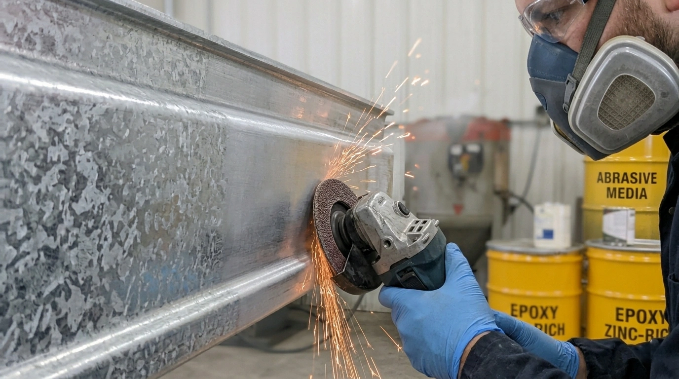
- Weld-repair / bonding boundary: the heat-affected zone plus pore growth plus hardness change from weld-repairing a structural part is normally not allowed as a cosmetic rework means, permitted only in non-load-bearing zones per the customer spec; the acceptability of surface melt treatment (remelting densification) on structural parts needs a per-plant agreement; for material shortfalls and small holes, prefer the "drill open—fill with sealant/putty—reseal" path, with putty and repair-system compatibility referring to the cure-window basis of the body-filler article: Automotive body filler: HG/T 4561 indices, cure window and spread-and-sand practice; the silicon-residue criterion for bonding interfaces goes back to Chapter 2—wherever a bonding zone is sanded, run a surface-energy verification first. Repaint of an already-coated part follows the wet-sanding-polishing boundary, not treating the "edge step" as a polishing problem: Automotive paint wet-sanding and polishing: grit sequence, machine parameters and hologram avoidance.
| Defect form | Permitted action | Hard boundary | Re-verification method |
|---|---|---|---|
| Electrodepinhole (isolated, small) | Local grind within the original dense layer, spot-seal then re-spray | Grinding must not penetrate the dense layer into the pore band; depth-gauge reading versus the drawing wall-thickness floor | Leak test / section check plus weight verification (MT grade) |
| Pinhole clusters / outgassing blisters | Full-face rework: strip coating → assess → reseal pores / e-coat off-line rework | Cumulative rework 2-pass ceiling (enterprise-standard basis) | Re-run dyne value plus water-break verification before re-entry |
| Crater / fisheye (silicon source) | Wipe and respray during wet-film; after cure grind through to a clean interface | No batch rework until the contamination source is closed (to prevent whole-tank contamination) | A/B coupon plus crater locations vs air flow / station correlation |
| Edge low film thickness / exposure | Re-apply edge seal plus local primer | Forbidden to break the galvanic isolation layer and not rebuild it | Coating-integrity check plus system-level salt-spray (GB/T 10125-2021) |
| Sink mark / cold-shut appearance defect | Non-Class-A faces accepted by limit sample concession; Class-A putty repair restricted | Putty thickness beyond window = bake cracking and later stain pickup | Limit-sample comparison plus film-thickness profile |
| Crack (any form) | Scrap unconditionally; no rework path | Cracks propagate under fatigue loading; zero tolerance for structural parts | Dye-penetrant / CT re-confirmation (NDE sensitivity per customer spec) |
5.4 The role of primer and the whole-vehicle system
For a mixed-body there is another often-overlooked relief item: the functions of primer (levelling, isolation, stone-chip buffering) determine that "one fewer high-temperature bake" benefits aluminium parts, so primerless/compact processes (B1B2, 3C1B) can combine with heat-treat-free alloy and low-temperature e-coat into a "whole-line thermal budget" plan; the levelling trade-off of primer is in this site's primer article: Automotive primer (midcoat): functions and application points—levelling, isolation and intercoat adhesion; the insulating anti-corrosion system for die-cast battery-tray-type parts is in Battery-enclosure anti-corrosion and insulating coatings: the two key technologies of traction battery pack protection; and the corrosion-resistance validation methods for an aluminium coating system (salt-spray, stone-chip, high-pressure wash-down comparison) have a systematic measured basis in Corrosion-resistance validation of automotive aluminium alloy wheel coatings.
6. Key data at a glance
- 38 mN/m: the dyne surface-energy risk line for a substrate to be painted; clean metal faces are typically 40~45 mN/m; silicone flow additives pull coating surface tension to 20~22 mN/m and fluorocarbon systems to 16~18 mN/m—the physical background of silicon contamination "failing at extremely low quantity" (public industry basis).
- about 3 μm/min: the alkaline etch rate of 5052/6061 aluminium at NaOH 30~40 g/L and 50 ℃ (1050 about 2 μm/min), roughly doubling for every 10 ℃ rise; a Na₂CO₃ 60 g/L, 60 ℃ system is below 1 μm/min (aluminium surface-treatment public-data basis).
- pH 3.8~4.2 / 20~35 ℃ / 60~120 s: the typical operating window of the zirconium/titanium nanoscale non-phosphate route (spray 60~120 s, immersion 90~180 s, free fluoride 10~100 ppm, film 50~150 nm, per public vendor TDS); if the pH floor fails = aluminium over-etching.
- 30~130 mg/m² vs 2.0~3.5 g/m²: the film-weight magnitude gap between an aluminium-compatible thin conversion film and a body zinc phosphate (GB/T 6807-2001 sets coating-grade phosphate film weight below 7.5 g/m²; the non-phosphate film-weight ceiling basis is 130 mg/m², about 1.8% of it).
- 170~180 ℃×20~30 min → 140 ℃: the conventional cathodic e-coat cure window (part-body-temperature basis) versus the low-temperature-cure e-coat of public patent CN105969057A; the low-temperature e-coat simultaneously gives a Ford-box throwing power no lower than 22 cm, a breakdown voltage no lower than 380 V, and an adjustable 10~30 μm film thickness.
- 240 MPa → 262 MPa: the measured tensile-strength change of an A356 cast wheel before and after coating bake (literature in《Hot Working Technology》, 2006 Issue 6), proving "bake = a second heat treatment"; in the same direction the wheel industry uses under-aging to suppress the post-bake hardness rise and impact-toughness drop (public patent background basis).
- 0.2 mm / 2 passes: common ceilings of enterprise work standards for die-cast rework (wall-thickness loss, rework count); weight-deviation verification cites the MT1~MT16 grades of GB/T 11351-2017《Tolerances for castings — Mass》, expressed as a percentage.
- 0.15 ml/100 g: the public-data basis for aluminium-melt degassing control (target hydrogen content for rotary degassing / inert-gas flux), a supply below this level being the precondition insurance for "no coating outgassing".
- 535~540 ℃ / 130~185 ℃: the solution-treatment and artificial-ageing temperature bands of Al-Si-Mg T6 (the《Physical Testing and Evaluation》2010 A356 wheel T6 optimisation literature gives schemes such as 535 ℃×6 h, 130~140 ℃×2.5~4 h); their overlap with the coating bake band is the conflict source.
7. Line-release decision and mixed-line management checklist
- The technical-agreement triad: release-agent grade plus residue limit (wipe method), soundness grade (X-ray/CT reference images plus leak test) plus heat-treatment state (including post-coating property requirements) written into one and the same incoming agreement; missing any one is handled as an open risk.
- First-article full-chain verification: before a new batch / new grade goes on line, run a four-stage short-path coupon "clean—non-phosphate—e-coat—bake": dyne value, water-break, film weight (interface check for a zirconium film, gravimetric method for phosphate per GB/T 9792/ISO 3892), e-coat pinhole count, and re-measured body hardness after bake.
- Two-temperature-zone management: run heat-treat-free alloy and T6 parts on separate fixtures with separate bake programs (dual limits of temperature peak plus cumulative time), and calibrate the oven profiler quarterly.
- Cross-contamination monitoring of tanks: daily check of non-phosphate tank pH/zirconium/free fluoride; visual oil-film check of e-coat UF permeate; read dissolved-aluminium and free alkalinity of the alkaline wash tank together—on the aluminium line "is the alkalinity enough" and "is the etch building up" are two faces of one coin.
- Defect database: record crater, pinhole and blister locations separately on maps, associated with die-casting heat lot and release-agent batch; within three months a "defect—incoming batch" regression line can be built that exposes problems earlier than any single-point decision.
- Rework discipline: log both depth-gauge readings plus whole-part weighing (MT-grade judgement) on the rework ticket; any rework beyond 2 passes triggers mandatory review; weld-repair in structural zones is forbidden by default.

| Feature | Crater / fisheye | Electrodepinhole | Bake outgassing blister (crater) | Undercut-corrosion blister |
|---|---|---|---|---|
| When it appears | Visible within seconds in the wet film | Visible after tank exit / drying | Newly appears or grows after the topcoat oven | Months to years after service |
| Morphology | Bright rim plus central depression, often showing through | Fine straight pinholes, mostly on flat/edge faces | Splash-rimmed hole mouths, clustered at hot-spot projections | Irregular raised mounds, corrosion products at the break |
| Root-cause direction | Surface-energy contamination (silicon/wax/oil) | Hydrogen evolution, tank impurities, over-window voltage | Subsurface pore outgassing plus early surface seal | Galvanic / missing seal / exposed edge |
| Verification method | Dyne pen plus A/B coupon plus FTIR | Voltage-profile review plus tank-filtration check | Section matched to X-ray/CT pore coordinates | On-site potential / crevice check plus coating peel analysis |
| Rework path | Wipe during wet-film; after cure grind to a clean interface | Re-grind and re-enter the line | Pore-seal pretreatment plus stepped-ramp recoat | Rebuild isolation and sealing (Chapter 5) |
8. Frequently asked questions (FAQ)
Q1 Is a water-based release agent inherently safe? Does switching to water-based solve craters?
It cannot be generalised. "Water-based" is only the carrier basis; the active component determines downstream risk: water-based silicone-free (polymer/ester emulsions) usually goes straight onto the paint line, whereas water-based silicone-containing (modified polysiloxane systems, silicone-oil share around the 15~18% level in publicly patented formulations) and silicone-wax composites still leave a low-surface-energy residue, so craters persist. The criterion is not the "water-based/solvent-based" label but: whether the downstream-compatibility declaration is zero-silicon, whether dilution and spray volume are controlled (over-spraying itself is a source of carbon build-up and subsurface gas), and the results of the first-article dyne value and water-break test at line entry. Any grade change must pass A/B coupon verification.
Q2 Why can't the pre-e-coat alkaline wash just be "turned up" to strip the residue in one pass?
Because for aluminium, more alkali = eating the substrate. Public aluminium-treatment data give an etch rate of about 3 μm/min at 50 ℃, NaOH 30~40 g/L, doubling for every 10 ℃ rise, and immersion tanks also compound surface roughness and mottling from dissolved-aluminium accumulation. The alkaline-wash window is a "enough to clean without etching" sandwich: first raise the degreaser's emulsifying/encapsulating capability (surfactant system, spray pressure, fresh-make-up rate) rather than free alkalinity; castings that genuinely need a strong-alkali pre-wash (heavy draw wax) should be handled in a dedicated stage using a cast-aluminium-specific silicate-inhibited formulation with dwell timed in seconds. If craters cannot be washed off, the answer is usually at the source in changing the chemical, not adding alkali downstream.
Q3 Must die-cast parts be X-rayed? How does a paint shop align acceptance with the foundry?
The paint shop need not take the films itself, but must require the casting to come with soundness evidence per batch and translate it into coating language. Note two realities: GB/T 11346-2018's public scope states it excludes aluminium alloy die castings, so there is no ready-made "national grade" to cite; the workable basis is three tiers—cosmetic faces aligned to the ISO 10049:2019 visual-grading framework and the signed-sample grade, internals judged by mutually agreed reference images/CT grading (written into the drawing), and functional hole positions adding leak-test sampling. The agreement should also state directly that "subsurface pores are not permitted to show visible outgassing defects under 170~180 ℃ bake", turning the coating result into an incoming criterion as well, otherwise the entire rework cost falls on the coating side.
Q4 Does a heat-treat-free alloy casting still need bake-temperature control?
Yes, but its nature changes. The heat-treat-free route cancels the "over-aging softening" layer of conflict, so bake no longer threatens strength; the remaining constraints are the outgassing window (as-cast porosity still vents), dimensional stability (residual stress still relaxes slowly) and temperature compatibility with adhesives/sealants. Thus the bake limit for heat-treat-free parts degrades from a "material-state limit" to a "process limit", and the conventional e-coat window can usually be accepted; still, keep records of the body-temperature curve and cumulative time—one rework is several rounds of thermal exposure, and heat-treat-free is not management-free.
Q5 Both low-temperature e-coat and UV curing "reduce heat"—how to choose?
Look at what the defect and the product need. Low-temperature e-coat (about 140 ℃ cure on a public-patent basis) solves the base-coat problem across the whole outer surface plus internal cavities—throwing power is retained and cavities are still coated; the cost is a narrower bath window and re-calibrated dry/crosslink takt. UV/LED covers only line-of-sight faces, gives no answer for cavities and shadow zones at all, and thick-film depth penetration, oxygen inhibition and powder/gel adhesion are all boundaries, so it suits exposed faces and quick-repair scenarios better. For a steel-aluminium mixed body the realistic combination is "cavities via e-coat (conventional or low-temp) plus exposed high-DFT via UV", or go 3C1B to drop one bake. Do not answer two problems with one process.
Q6 On a steel-aluminium co-line, does the e-coat tank need to be adjusted separately for aluminium?
What to watch is not "switching to an aluminium version of the formula", but the three drifts aluminium brings: dissolved aluminium from the alkaline-wash stage entering the tank system, amphoteric attack on aluminium by interfacial alkalisation (showing as adhesion mismatch and pinhole clusters), and hydrogen gas films lingering on wide flat faces. Management actions: daily control of tank pH/conductivity/solids (within the 18~25 μm e-coat-film basis, drift magnifies pinhole differences), staged voltage ramp with lower current density over casting flat faces, and load accounting of the ultrafiltration and anolyte systems. The two e-coat articles on this site give the full bath-management parameters: Cathodic e-coat principles and parameters: throwing power, voltage and bath management. The steel-aluminium separate-line/co-line decision on the pretreatment side must be cross-checked against the non-phosphate window (Q2).
Q7 For die-cast coating-defect rework, who really decides "how deep to grind"?
Three things decide it: the drawing's wall-thickness floor, the dense-skin position, and the weight evidence. Operationally: first check the drawing wall-thickness floor at that point (integrated rear-floor main load-bearing zones about 4 mm, non-critical zones about 2.5 mm on a publicly reported basis), and write "stop when grinding reaches the pore band" into the work card; control each pass's removal with depth-gauge readings, and directly cite into the plant agreement the enterprise-standard-common 0.2 mm wall-thickness-loss ceiling and the "rework no more than 2 passes" rule; weigh the whole part against the MT grades of GB/T 11351-2017. Cross any boundary and the disposition switches from "rework" to "review / concession / scrap", with no third grinding pass allowed.
Q8 Should integrated die-cast parts be accepted against a whole-vehicle salt-spray standard? How must the test be run to be meaningful?
A single-point "XX hours" has no acceptance value; only a system-level designed test does. A workable scheme: take the first-article-at-line and a rework-ceiling part and run a salt-spray with cross-hatch / crevice simulation (per the GB/T 10125-2021/ISO 9227 basis), assessing three items—e-coat integrity (pinhole rate), edge-seal effectiveness (corrosion spread from the break), and non-phosphate interface adhesion (cross-hatch judged at grades 0~1); scale up as a cyclic combination against the vehicle anti-corrosion target (salt-spray plus stone-chip plus temperature-humidity cycling). This site already has a reusable measured framework: Corrosion-resistance validation of automotive aluminium alloy wheel coatings: salt-spray, stone-chip and high-pressure wash-down comparison. Write the conclusions back into the technical agreement, and only then does the next batch truly get cheaper.
9. References and basis notes
- GB/T 11346-2018《Radiographic testing of aluminium alloy castings — Defect grading》(issued 2018-07-13, implemented 2018-08-01, replacing GB/T 11346-1989; the public abstract notes it applies to aluminium alloy castings with transmitted thickness not greater than 50 mm and does not apply to defect grading of aluminium alloy die castings or of cracks and cold shuts); GB/T 5677-2018《Castings — Radiographic testing》.
- ISO 10049:2019《Aluminium alloy castings — Visual method for assessing porosity》(2nd edition, issued 2019-06-19, replacing the 1992 edition; the grading illustrations and test conditions are per the public restated basis).
- GB/T 15114-2023《Aluminium alloy die castings》(current, replacing the 2009 edition; the 2009 edition implemented 2009-12-01 and was withdrawn 2023-05-30, having modified-adopted ASTM B85-03); GB/T 15115-2024《Die-casting aluminium alloys》; GB/T 11351-2017《Tolerances for castings — Mass》(issued 2017-11-01, implemented 2018-05-01, MT1~MT16 grades).
- GB/T 6807-2001《Technical conditions for phosphating of steel parts before painting》(coating-grade phosphate film weight below 7.5 g/m², 3% NaCl immersion criterion); GB/T 11376-2020 (= ISO 9717:2017); GB/T 9792 (= ISO 3892, gravimetric film-weight method); GB/T 10125-2021 (= ISO 9227:2017, salt-spray); GB/T 2828.1-2012 (AQL sampling).
- Chen Kuang, Guan Shaokang, et al.:《Optimisation study of the T6 heat-treatment process for cast aluminium alloy wheels》,《Hot Working Technology》, 2006 Issue 6 (A356 tensile 240→262 MPa and elongation 8%→9% after coating bake); Fan Wenjing, et al.:《Optimisation of the T6 heat-treatment process for A356 aluminium alloy wheels》,《Physical Testing and Evaluation》, 2010, Vol. 46 Issue 11 (solution treatment 535~540 ℃, ageing 130~140 ℃×2.5~4 h, and other optimised schemes); Pan Hao, et al.:《Effect of ageing temperature and time on the microstructure and properties of A356 aluminium alloy under low-intensity pulsed magnetic field》,《Mechanical Engineering Materials》, 2023, Vol. 47 Issue 8 (comparison of conventional ageing-band schemes at 175~185 ℃).
- Public technical literature on aluminium-profile surface treatment (Chinese aluminium-profile industry websites and vendor technical notes): at NaOH 30~40 g/L and 50 ℃, 1050 about 2 μm/min and 5052/6061 about 3 μm/min; the rate roughly doubles per 10 ℃; Na₂CO₃ systems below 1 μm/min; alkaline-etch operating window at the 40~55 ℃ / 20~120 s level.
- Vendor public-data basis: Henkel BONDERITE M-NT 1800A zirconium/titanium non-phosphate (pH 3.8~4.2, 13~46 ℃, spray 60~120 s, film 50~150 nm, free fluoride 10~100 ppm); publicly listed non-phosphate grades film weight 30~130 mg/m²; BONDERITE 333RELEASE 2, L-CA CP 799 and other silicone-free water-based die-casting release-agent TDS; die-casting release-agent classification and defect mapping (water-based/solvent/wax/polysiloxane families, die temperature 150~320 ℃, dilution 10~100×).
- Published patent literature: CN105969057A《A low-temperature-curing cathodic electrocoat coating and its preparation process》(published 2016-09-28; cure 140 ℃, film thickness 10~30 μm, Ford-box throwing power no lower than 22 cm, breakdown voltage no lower than 380 V, background basis of conventional CED 170~180 ℃); the Tesla die-cast aluminium alloy patent (grade reference CN112567059 on a publicly reported basis); public reporting of integrated die-casting and heat-treat-free alloy industrialisation (6 000 t-class Giga Press, parts 70→1~2, about 2 000 fewer weld points, roughly a third lighter, roughly 40% cost reduction, all media-restated figures).
- Public technical data on coating defects and surface energy: the dyne 38 mN/m criterion, silicone flow additives 20~22 mN/m, fluorocarbon 16~18 mN/m; FTIR/microscopy root-cause analysis; outgassing and pre-bake degassing, pore-sealing primer as powder/die-cast industry consensus (public posts in coating-technology communities).
Basis note: the standard numbers, issue/implementation dates and scopes in this article have been checked against the National Standard Information Public Service Platform and the standard-information service network; the process figures from vendor TDS, industry literature and media reports are on a public-data basis, vary with grade, batch and line conditions, and are intended for selection communication and defect troubleshooting, not as arbitration grounds—formal determinations rely on the current original standard text, supplier technical documents and the customer drawing. Enterprise-work-standard figures (rework count, wall-thickness loss, zone limits) are restatements of publicly visible in-plant standards and must be re-agreed in the contract when cited.
Last updated: 2026-11-03 | Attribution: Kexin New Materials (Guangdong) Co., Ltd. (B2B technical literature, trade-terms basis EXW / FOB)