Cathodic Electrophoretic Deposition (CED) is the most fundamental and indispensable process in the anti-corrosion system of modern automotive bodies. Whether it is a passenger car body-in-white, a commercial vehicle frame, or various metal structural parts formed by stamping and welding, almost all must first go through an electrophoresis to form a continuous, uniform organic coating that can penetrate into inner cavities and seams, before the intermediate coat, pigmented paint, and varnish come into play. Starting from the physicochemical principles of electrodeposition, this article systematically explains the difference between anodic and cathodic reactions, the trade-off between epoxy and acrylic electrophoretic resins, and the bath management parameters that truly determine whether a workshop can produce stably—voltage, solids content, pH, temperature, and throw power. It should be noted that the electrophoretic process parameters listed in this article are all from this batch of research archives (automotive coating system and process section): voltage 200–350 V, bath solids content 15–20%, pH 5.8–6.2, temperature 28–35℃. At the level of anti-corrosion philosophy, cathodic electrophoresis and industrial protective coating share the same underlying logic—cathodic protection, barrier, and compatibility; readers may also refer to industrial coating compatibility articles for further selection guidance.
I. Why the First Coating Layer for Automotive Anti-Corrosion Must Be Electrophoresis
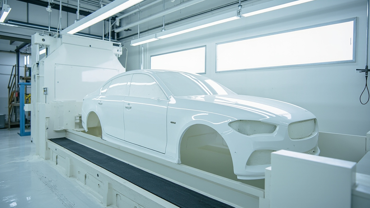
Before discussing the principles, it is necessary to understand why electrophoresis is placed at the very front of the overall painting process. An automotive body is assembled from hundreds of steel sheets via spot welding, laser welding, and riveting, resulting in numerous lap seams, cavities, and box-shaped structures (such as rocker panels, longitudinal beams, and door inner panels). These locations cannot be reached by traditional spray guns, yet they are the corners where moisture, chloride ions, and oxygen most easily penetrate to cause rust. If bare steel after sandblasting relies only on the intermediate coat and topcoat for protection, no problem is visible in the short term, but after three to five years the lower edges of doors and the inner sides of wheel arches will blister and perforate from the inside out—this is the core pain point that electrophoresis solves: it uses an electric field to "pull" charged paint particles into all conductive gaps, forming a uniform primer film that even spray guns cannot reach.
From the perspective of the overall painting process chain, the standard four steps of OEM (original factory painting) are: pre-treatment (degreasing, phosphating or silane treatment, generating a conversion film to improve adhesion and corrosion resistance) → cathodic electrophoresis (CED) → intermediate coat (improving leveling and stone-chip protection) → pigmented paint and varnish (baked into film). The electrophoretic layer is directly attached to the conversion film and is the anti-corrosion interface truly "zero-distance" from the metal; therefore, its continuity and inner cavity coverage directly determine whether the vehicle's ten-year anti-corrosion warranty can be fulfilled. In other words, electrophoresis is the foundation of the vehicle's anti-corrosion warranty promise; no matter how beautiful the intermediate coat and topcoat are, they cannot compensate for the inner cavity rust hidden by a missed electrophoretic layer. According to this batch of research archives (automotive coating system and process section), the key operating parameters of the electrophoresis bath are: voltage 200–350 V, bath solids content 15–20%, pH 5.8–6.2, temperature 28–35℃, and the throw power index should also be monitored.
II. Electrodeposition Principle: What Exactly Happens at the Anode and Cathode
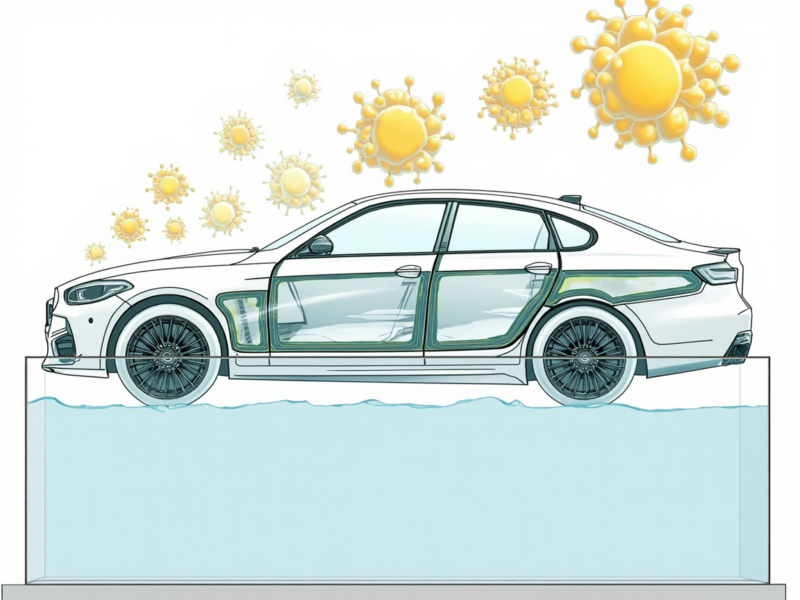
Electrophoresis is essentially the directional migration and deposition of water-based colloidal particles under a direct current electric field. The bath is an emulsion mainly of deionized water with a small amount of organic solvent; the resin is dispersed in it as positively charged colloidal particles (latex particles), with pigments and fillers encapsulated or adsorbed within the micelles. The workpiece (body) is connected to the negative pole of the DC power supply (cathode), and the bath electrode is connected to the positive pole (anode, usually stainless steel or an inert electrode). After energization, the positively charged resin particles migrate toward the cathode and lose their charge, dehydrate, and deposit into a film at the workpiece surface—this is the origin of the name "cathodic electrophoresis."
Here it is necessary to distinguish "anodic electrophoresis" from "cathodic electrophoresis." Early electrophoresis was anodic (workpiece connected to positive pole), with negatively charged resin migrating toward the anode. But anodic electrophoresis has a fatal flaw: the workpiece as anode undergoes metal dissolution; iron ions entering the bath contaminate the paint film, causing the film to yellow and become brittle, and the iron itself is electrochemically corroded, making its anti-corrosion inferior to the cathodic system. Cathodic electrophoresis sets the workpiece as the cathode; the reaction at the workpiece surface is reduction (hydrogen evolution), and the base metal is not oxidized or dissolved, so its salt spray resistance is significantly better than anodic electrophoresis—this is the fundamental reason why contemporary automobiles have almost entirely shifted to cathodic electrophoresis.
The specific electrode reactions can be broken down as:
Cathode (workpiece) side main reactions:
- Reduction of water: 2H₂O + 2e⁻ → H₂↑ + 2OH⁻, the area near the workpiece surface becomes alkaline due to continuous generation of OH⁻;
- Resin colloidal particles (positively charged) migrate to the cathode, coagulate and deposit in the alkaline environment, accompanied by mechanical extrusion dehydration, gradually transforming from wet latex to a continuous wet film.
Anode (bath electrode) side main reactions:
- Water or stainless steel passivation film participates in reaction releasing O₂: 2H₂O → O₂↑ + 4H⁺ + 4e⁻;
- If the anode material is improperly selected (e.g., using soluble iron electrodes), metal ions will dissolve and contaminate the bath, so modern CED widely uses insoluble anodes (DSA-coated titanium electrodes or cathodic protection designs isolated by independent anode cages) to minimize metal ion dissolution.
Understanding these reactions is extremely important for on-site management: cathodic hydrogen evolution causes bubbles to be trapped in the film; if the voltage is too high or heating too fast, bubbles that cannot escape in time will form pinholes; anodic oxygen evolution, if mixed into the bath, will oxidize the resin, so the anode zone must be independently circulated and de-aerated promptly. Electrophoresis is not "just turn on the power and done," but a continuous control of electrochemical by-products. From a colloid chemistry perspective, resin particles rely on cationic groups (such as amine salts) adsorbed on the surface to obtain Zeta potential for stable dispersion; after energization, particles migrate in the electric field and destabilize and coagulate at the cathode; the whole process is extremely sensitive to bath conductivity and ionic strength—this is why conductivity must be strictly suppressed by UF and ion exchange. If conductivity loses control, particles will flocculate prematurely in the bath, clogging filters and ruining the film surface; the coupling relationship with voltage and pH is precisely the most difficult and skill-demanding part of bath management.
III. Two Resin Systems: How to Choose Between Epoxy and Acrylic
The film-forming resins of cathodic electrophoretic paint mainly fall into two camps—epoxy and acrylic—which have clear divisions in performance orientation; choosing the wrong system will directly drag down the vehicle's corrosion resistance or weatherability.
| Comparison Dimension | Epoxy Cathodic Electrophoretic Paint | Acrylic Cathodic Electrophoretic Paint | |
|---|---|---|---|
| Core Resin | Epoxy resin (with amine-modified cationic groups) | Acrylic copolymer (cationized) | |
| — | Anti-corrosion / Salt Spray | Excellent, strong adhesion to bare steel, good barrier | Good, but overall corrosion resistance slightly inferior to epoxy |
| Weathering / Gloss Retention | Average, prone to chalking under long-term outdoor exposure | Excellent, UV resistant, good gloss and color retention | |
| Typical Use | Body inner cavities, frames, chassis and other heavy anti-corrosion parts | Exposed parts with high appearance and weathering requirements | |
| Compatibility Positioning | Mostly as bottom anti-corrosion main film | Often synergizes with topcoat to enhance appearance durability | |
| Bath Stability | Mature and robust, widest industrial application | Requires more precise pH and solvent balance |
In short, the epoxy system wins at "protecting well," and the acrylic system wins at "withstanding sunlight." On passenger car body-in-white lines, epoxy CED is the absolute mainstream because it must uphold the ten-year anti-corrosion promise; while on some parts with higher requirements for appearance weathering and less prone to water accumulation structurally, the acrylic system is selected. It should be reminded that regardless of resin type, the continuity of the final film affects anti-corrosion more than the resin type—an electrophoretic layer with pinholes and missed coating cannot be saved by any good resin for the vehicle's anti-corrosion life.
From a selection implementation view, another advantage of the epoxy system is mature bath technology, wide process window, and high tolerance to pre-treatment fluctuations, making it more suitable for high-volume continuous lines; the acrylic system is more demanding on bath pH and solvent balance, with slightly higher maintenance cost. Therefore, vehicle manufacturers generally prefer epoxy for body-in-white, leaving the "withstand sunlight" task to the upper intermediate coat and varnish, rather than letting the bottom electrophoresis also handle weathering. This idea of "each layer has its own role, no overstepping" is itself an extension of the layered compatibility philosophy.
IV. Core Process Parameters: Voltage, Solids, pH, Temperature, and Throw Power
This section lays out all the hard parameters that can be written into the standard operating procedure (SOP). Data are based on this batch of research archives (automotive coating system and process section).
(1) Voltage 200–350 V. Voltage determines deposition driving force and film thickness upper limit. Too low voltage leads to insufficient throw power and poor inner cavity coating; too high voltage causes violent hydrogen evolution on the workpiece surface, with pinhole, orange peel, and breakdown risks surging. Actual lines often do not use constant voltage, but adopt "soft start + stepped boost" or "constant current density" control: enter bath at lower voltage to let surface film uniformly, then gradually increase to push paint particles into deep cavities. For complex bodies, segmented voltage curves are more reliable than a single fixed voltage.
(2) Bath Solids Content 15–20%. Solids content is the mass/volume ratio of non-volatile components in the bath, directly determining how much dry film can be brought out per deposition. Too low solids leads to thin film, insufficient hiding and anti-corrosion; too high makes bath viscous, poor leveling, easily clogs filter bags, and more paint carried away by washing. 15–20% is a classic range balancing deposition efficiency and bath stability, maintained on site by adding original paint and deionized water.
(3) pH 5.8–6.2. The cathodic electrophoresis bath is a weakly acidic environment. Too low pH (over acidic) makes resin particles too stable, slow or even no deposition; too high pH (toward neutral) makes particles coagulate easily, bath unstable, and particles coarse. pH is mainly maintained by H⁺ from anodic reaction and the weak acid buffer of the replenishment system; daily it must be locked within the 5.8–6.2 window by regular testing and adding dedicated adjusters.
(4) Temperature 28–35℃. Bath temperature affects viscosity, deposition rate, and leveling. Too low temperature slows deposition, thin film and poor leveling; too high makes solvent evaporate fast, bubbles hard to eliminate, resin prone to curing degradation. 28–35℃ is controlled in closed loop by external heat exchange units (plate heat exchanger + cooling/heating), the most "physical" and most cannot-fail link in electrophoresis bath management.
(5) Throw Power.
Throw power refers to the ability of the paint bath to penetrate into cavities and crevices far from the main electrode and deposit uniformly under an electric field, and is the core value distinguishing electrophoresis from spraying. It is jointly affected by voltage, solids content, pH, solvent type and content, and workpiece geometric complexity. On-site, the "Ford Box" or tubular specimens are commonly used to measure the coating height inside cavities for evaluation. Traces of insufficient throw power: bare steel or abrupt film thickness drop at the lower part of door inner panels, inside longitudinal beams, and backs of studs. Improving throw power usually starts with increasing voltage, optimizing auxiliary anode layout, and adjusting bath solvent balance, rather than simply increasing solids content.| Parameter | Typical Range | Low-side Risk | High-side Risk |
|---|---|---|---|
| Voltage | 200–350 V | Insufficient throw power, missed coating in cavities | Hydrogen evolution pinholes, breakdown, orange peel |
| Solids content | 15–20% | Thin film, insufficient anti-corrosion | Poor leveling, filter clogging, waste |
| pH | 5.8–6.2 | Slow deposition, no deposition | Coagulation, coarse particles, instability |
| Temperature | 28–35℃ | Slow deposition, poor leveling | Bubbles, curing degradation |

V. Bath Management: Synergistic Monitoring of Solids, pH, Conductivity and Solvent
The real skill in an electrophoretic coating workshop lies not in "energizing", but in "maintaining the bath". The bath is a dynamic system continuously carried out by workpieces, replenished with original paint, cleaned by ultrafiltration (UF), and diverted by anolyte. Any drift in any indicator will accumulate into batch quality incidents. The following four quantities must be treated as daily routine功课:
Solids content monitoring. Measure bath solids content (oven method or rapid moisture analyzer) once a day, linked to original paint replenishment. Replenishment should be "small amounts, multiple times" to avoid local concentration shock and flocculation from a one-time large refill. Also record the paint carried away by vehicle bodies (estimated by output and film thickness), so that replenishment matches actual consumption.
pH monitoring. Use a precision pH meter at least once per shift. pH drift often indicates abnormal anode system or replenishment agent imbalance. Note that the pH meter must be calibrated regularly; the electrode is easily contaminated by the bath and should be replaced per manufacturer's cycle.
Conductivity monitoring. Conductivity reflects the total ion amount in the bath. Salts brought in by inadequate pretreatment rinsing, anolyte backflow, and replenishment agent accumulation all push up conductivity, causing rough films and more pinholes. Modern CED is generally equipped with UF and anion/cation exchange resins to continually purify, keeping conductivity within the process window. If conductivity rises abnormally, first check whether the final pure water rinse in pretreatment meets standards, then check whether the UF loop is clogged.
Solvent content monitoring. Cathodic electrophoretic bath contains a small amount of coalescing/film-forming solvent (e.g., glycol ether class), which affects deposition, leveling and throw power. Solvent volatilization and carry-out reduce content, requiring quantitative replenishment based on bath analysis; excess makes the film soft and sagging. Solvent management is often tied to VOC compliance; the workshop must have enclosed collection and exhaust treatment, meeting requirements of national standards for harmful substance limits in automotive coatings (e.g., GB 24409-2020).
In addition to the four hard indicators, the health of the ultrafiltration (UF) system directly determines bath life: UF membranes separate excess paint and impurities washed off, and return clean water for post-rinsing, saving water and reducing discharge. Declining UF flux and rising differential pressure are signals for chemical cleaning or membrane module replacement.
Another often overlooked loop is the anolyte circulation system. Modern CED mostly uses insoluble anodes (e.g., DSA-coated titanium electrodes); the anode chamber is separated from the bath by an ion-exchange membrane, and anolyte flows in an independent closed loop, carrying away H⁺ produced by anode reactions and possibly dissolved trace metal ions, maintaining bath pH stability and preventing metal ion contamination of the paint film causing yellowing and embrittlement. Anolyte itself should be monitored for conductivity and flow; flow interruption will instantly crash anode zone pH and cause resin coagulation and scaling at the anode, then contaminate the entire bath. Many "sudden bath degradation" cases trace back to anolyte pump or membrane module failure, so the anolyte loop and UF loop should be included in daily inspection alongside each other.
VI. Post-rinse and Baking: The Last Two Steps of the Film-forming Loop
The electrophoretically deposited layer is still a semi-film of "wet film + entrained bath", and must go through post-rinse and baking to truly form a film.
Post-rinse (UF water wash + pure water wash). When the workpiece leaves the bath, its surface is covered with large amounts of paint-containing bath. If baked directly, this bath will form a rough, brittle waste film, wasting paint and ruining appearance. Post-rinse first uses UF permeate to wash off surface floating paint and recover it (recovered paint returns to bath), then uses deionized water (or pure water) for final rinse, ensuring only a uniform wet film remains on the surface. Rinse pressure, direction, and drain time must be standardized to avoid "water marks" and unrinsed blind spots.
Bake curing. The washed wet film enters the oven and crosslinks and cures under a set temperature profile — epoxy systems rely on functional groups in the resin and curing agent (or self-crosslinking groups) to form a 3D network. Insufficient baking leaves the film soft, with substandard adhesion and corrosion resistance; overbaking makes the film brittle and discolored. Typical CED baking is in the 160–180℃ range, controlled by panel temperature time (not just oven air temperature). The oven needs good temperature uniformity, avoiding cold spots causing local uncured areas.
At this point, a continuous, dense, cavity-fully-covered cathodic electrophoretic primer film is completed, on which intermediate coat and topcoat can be applied.
VII. Anti-corrosion Thinking of Industrial Coatings from Electrophoresis: Cathodic Protection, Barrier and Compatibility
Although cathodic electrophoresis belongs to automotive painting, its anti-corrosion philosophy is completely consistent with industrial protective coatings: "keep corrosive media from reaching the metal". Placing this thinking into the larger industrial anti-corrosion framework helps readers build systematic cognition, and related compatibility selection can also refer to industrial coating compatibility articles (see extended reading).
Cathodic protection thinking. In heavy industrial anti-corrosion, epoxy zinc-rich primer relies on ≥80% by mass zinc powder in dry film as sacrificial anode, preferentially corroded to protect the steel substrate; although electrophoresis contains no zinc powder, its dense continuous base layer also cuts off the "water path" of the corrosion galvanic cell. The common underlying logic is: electrically isolate the metal from the electrolyte environment, or provide a preferentially sacrificial anode path.
Barrier thinking. Epoxy micaceous iron oxide intermediate coat relies on mica iron oxide flakes to lengthen the diffusion path of water, oxygen, and chloride ions, equivalent to building a "maze" inside the film; the dense continuity of the electrophoretic film is essentially also a barrier — except it achieves full coverage via electric field, leaving no spray-gun dead corners.
Compatibility thinking. The ISO 12944 system emphasizes layered compatibility of "primer (anti-corrosion/adhesion) + intermediate coat (thickening/barrier) + topcoat (weathering/decorative)". The vehicle painting process of pretreatment → electrophoresis → intermediate coat → pigmented paint → varnish is exactly a vehicle-scale replica of this philosophy: each layer manages one segment, stacking anti-corrosion and aesthetics far beyond a single layer. In corrosion grade classification, ISO 12944-2018 grades environments from C2 (low) to C5 (very high) to CX (extreme offshore), and sets Im1–Im3 immersion grades; heavy anti-corrosion epoxy zinc-rich primer (e.g., Jotun Barrier 80 UHS in the archive) can reach "very high (VH)" durability under C5. The positioning of the electrophoretic layer is equivalent to the "CED-grade base layer" of the vehicle system, and its durability goal should also be defined in corrosion grade language rather than just reporting a salt spray hour count. Kexin New Materials (kexinMaterials) has long followed the layered compatibility principle of "base-layer anti-corrosion — middle-layer barrier — top-layer weathering" in industrial protection and automotive-related coating fields, highly homologous to the vehicle logic of electrophoresis — intermediate coat — topcoat, providing direct reference value for engineers needing cross-scenario anti-corrosion system design.
VIII. Common Electrophoretic Defects and On-site Troubleshooting
Even if parameters are within windows, various defects still appear on site; the key is to quickly map phenomena to "electrochemical by-products" or "bath drift". The following lists troubleshooting points by frequency.
| Defect Appearance | Most Likely Cause | On-site Countermeasure |
|---|---|---|
| Pinholes / Pits | Excessive voltage hydrogen evolution, high bath temperature hard-to-dissipate bubbles, pretreatment residue | Lower voltage, stabilize bath temperature, check degreasing and pure water rinse |
| Cavity missed coating / thin film | Insufficient throw power, poor auxiliary anode layout | Optimize voltage curve, add auxiliary anodes, calibrate throw power |
| Surface roughness / particles | High conductivity, bath contamination, declining UF flux | Check salts brought by pretreatment, strengthen UF/ion exchange |
| Film embrittlement / discoloration | Overbaking, pH drift causing resin degradation | Calibrate bake profile, lock pH, add adjuster |
| Local no paint | Poor fixture conductivity, improper masking | Clean fixture, check contact resistance, rearrange tooling |
| Edge / sharp corner over-thick | Edge effect electric field concentration | Stepwise voltage rise, add shielding, control voltage upper limit |
The essence of this table is "locate the variable first, then adjust a single parameter", avoiding changing multiple items at once leading to unattributeable causes. Most production line fluctuations can be rooted in the bath's four routine tasks (solids, pH, conductivity, solvent) and the anode/UF system, rather than blaming the electrophoretic paint quality itself.
IX. Migrate Electrophoresis Experience to Your Coating Decisions
For engineers engaged in automotive manufacturing, parts supply, or industrial equipment protection, understanding cathodic electrophoretic paint has at least three practical implications: First, when auditing a supplier's electrophoretic line, one can use "whether the voltage curve is reasonable, whether throwing power is actually measured, and whether the four key bath parameters have SOPs" as a due diligence checklist; Second, when designing an anti-corrosion system oneself, one can draw on the electrophoretic idea of "full electric field coverage" and prioritize processes that can enter internal cavities for complex structures; Third, when comparing the costs of different coating schemes, the "internal cavity anti-corrosion life" should be included in the total cost of ownership, rather than only looking at the unit price of the topcoat.
Returning to the technology itself, the stable output of cathodic electrophoretic paint does not rely on mysticism, but on the continuous control of the five parameters—voltage, solids content, pH, temperature, and throwing power—and the meticulous maintenance of the bath, ultrafiltration, and anode systems. In joint development with customers, Kexin New Materials (kexinMaterials) found that the vast majority of electrophoretic quality fluctuations can ultimately be traced to two areas: the "four basic tasks of the bath" and "pretreatment pure water rinse"—only by holding the fundamentals can the salt spray resistance of the electrophoretic layer and the vehicle's ten-year anti-corrosion commitment stand on solid ground.
FAQ
Q: What is the fundamental difference between cathodic electrophoresis and anodic electrophoresis?
A: The fundamental difference lies in the polarity of the electrode connected to the workpiece. In cathodic electrophoresis, the workpiece is connected to the negative electrode, and a reduction hydrogen evolution reaction occurs on the surface; the metal substrate is not oxidized or dissolved, giving better corrosion resistance. In anodic electrophoresis, the workpiece is connected to the positive electrode, causing metal dissolution, iron ion contamination of the paint film, and making the film brittle and yellowing. Modern automobiles almost exclusively use cathodic electrophoresis.
Q: Does higher voltage always mean better throwing power?
A: It is not a monotonic relationship. Too low voltage results in insufficient coating on internal cavities; too high voltage causes intense hydrogen evolution, producing pinholes, orange peel, or even breakdown. Production lines commonly use a "soft start + stepped voltage rise" curve to balance film thickness and pinhole risk; throwing power relies more on the comprehensive optimization of the voltage curve, auxiliary anode layout, and solvent balance.
Q: How is the bath solids content of 15–20% maintained?
A: Through a closed loop of "detection—replenishment—carry-out": measure solids content each shift, estimate the paint amount carried away by the vehicle body based on output and film thickness, and add small amounts of original paint and deionized water multiple times to avoid local concentration shock and flocculation caused by a single large replenishment.
Q: Why must pH be controlled within such a narrow range of 5.8–6.2?
A: The cathodic electrophoresis bath is a weakly acidic colloidal dispersion system. Too low pH causes excessive resin stability, slow or even no deposition; too high pH causes particle agglomeration, bath instability, and coarsening of particles. pH is determined by the anodic reaction and replenishment buffer, and must be checked regularly and locked within the window using adjusters.
Q: How is throwing power quantified on site?
A: Commonly, a Ford Box or tubular internal cavity test piece is used to measure the height and uniformity of coating on the inner wall after the paint penetrates the cavity. In daily monitoring, whether the lower part of door inner panels, longitudinal beam cavities, or the back of studs show exposed iron or abrupt film thickness drop are intuitive signals of insufficient throwing power.
Q: Why is UF post-rinse necessary after electrophoresis?
A: The workpiece exiting the bath is covered with large amounts of paint-containing bath liquid; direct baking would form a rough, brittle waste film, wasting paint and ruining appearance. UF permeate first washes off the floating paint and returns it to the bath, followed by a final pure water rinse, leaving only a uniform wet film for baking—ensuring quality while saving water and reducing emissions.
Q: What is the general salt spray resistance of the electrophoretic layer?
A: Specific values depend on the resin system, film thickness, and pretreatment quality, and should be based on the corresponding product's TDS and third-party testing. Engineering-wise, electrophoresis is the foundation of the vehicle's ten-year anti-corrosion commitment; combined with good pretreatment and subsequent intermediate coat and topcoat, the overall body anti-corrosion life is significantly improved. During selection, suppliers should be required to provide GB/T 1771 or ASTM B117 salt spray data and verify the test conditions.
Q: How is the VOC of cathodic electrophoretic paint controlled?
A: The bath contains small amounts of solubilizing/film-forming solvents, and volatilization and carry-out cause VOC emissions. The workshop needs enclosed collection, exhaust gas treatment, and must meet the national standard for limits of harmful substances in vehicle coatings (e.g., GB 24409-2020); solvent replenishment should be quantified based on bath analysis results, as excess causes the film to soften and sag.
Q: Why must temperature be stabilized at 28–35℃?
A: Temperature affects bath viscosity, deposition rate, and leveling. Too low slows deposition and yields thin films with poor leveling; too high accelerates solvent volatilization, makes bubbles hard to eliminate, and causes resin premature aging and degradation. Closed-loop temperature control via external plate heat exchangers is the physical link in bath management that can least afford to fail.
Q: Can electrophoresis directly replace industrial zinc-rich primer?
A: It cannot be simply replaced. Electrophoresis suits batch parts that can be immersed, are conductive, and geometrically suitable for electric field coverage; large steel structures and on-site construction scenarios that cannot be immersed still rely on spray systems such as epoxy zinc-rich primer. Both share the "base-layer anti-corrosion" philosophy, but their application boundaries are completely different; selection should be based on workpiece size and production line conditions.