In heavy-duty anti-corrosion coating systems, zinc-rich epoxy primer is responsible for "electrochemical protection", aliphatic polyurethane topcoat is responsible for "weather resistance and aesthetics", while the layer sandwiched in between and usually the thickest—micaceous iron oxide epoxy intermediate coat (commonly called "MIO intermediate coat" or "epoxy MIO" in the industry)—plays an underestimated yet most critical role: thickening and barrier. It contains no zinc, relies not on cathodic protection, and rarely faces UV directly, yet uses a seemingly plain physical principle to greatly lengthen the path for water, oxygen, and chloride ions to permeate the steel surface, thereby significantly extending the service life of the entire system. This article systematically explains the working mechanism and design essentials of MIO intermediate coat—from the flake morphology, layered arrangement, and barrier mathematical model of micaceous iron oxide (MIO, Micaceous Iron Oxide) to engineering systems—to help engineers correctly understand "why the intermediate coat is usually the thickest", and how to use it correctly and sufficiently in harsh environments such as bridges, storage tanks, and offshore platforms.
Kexin New Materials (kexinMaterials) in bridge, storage tank, and offshore platform systems, generally uses epoxy MIO intermediate coat as the main load-bearing layer of total dry film thickness, and determines its single-coat and total thickness according to the system table of ISO 12944-5, ensuring that the barrier thickness matches the functional division of primer and topcoat, turning "thickening" into an acceptable, verifiable number rather than a verbal promise, and facilitating supervision to check section by section against data.
I. What is Micaceous Iron Oxide Intermediate Coat
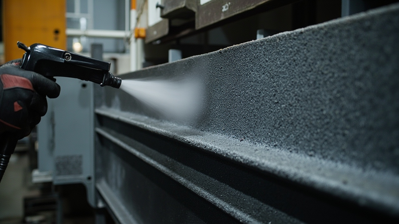
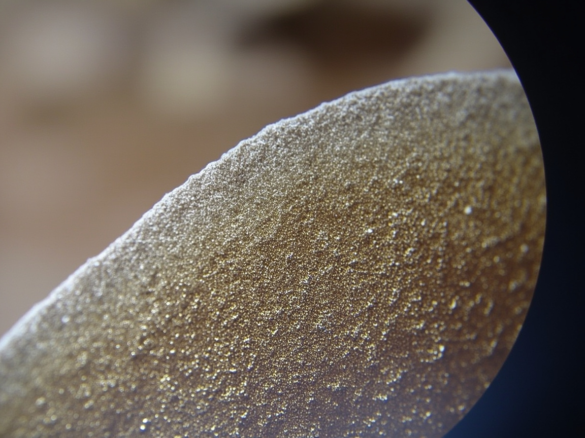
Micaceous iron oxide (MIO) is a natural or synthetic α-Fe₂O₃ flake, with a thin plate-like crystal shape and a large aspect ratio (often 10:1 to several tens to one), chemically stable, inert, and insoluble in water. It is added at a high proportion into an epoxy resin system and ground and dispersed to make epoxy MIO intermediate coat. After curing, countless MIO flakes lie parallel and overlapping in the paint film, covering layer upon layer like roof tiles. This structure seems simple, yet it is one of the most mature and cost-effective flake barrier solutions in heavy-duty anti-corrosion engineering.
It belongs to the "intermediate coat (intermediate / tie coat)", located between the primer and the topcoat. Its main function is not decoration (colors are mostly dark gray, reddish brown), but increasing barrier thickness, strengthening interlayer adhesion, and homogenizing system stress. Understanding its positioning is the key to understanding the layered logic of the entire system—it is neither a substitute for the primer nor a thickened version of the topcoat, but an independent "barrier layer". In the ISO 12944 series standards, this three-layer division of "primer provides cathodic protection, intermediate coat provides barrier and thickening, topcoat provides weather resistance" is repeatedly emphasized as the basic framework of system design; any modification that omits the intermediate coat will directly weaken the durability rating of the system.
II. Barrier Mechanism: the "Labyrinth Effect" of Flake Fillers
The anti-corrosion capability of MIO intermediate coat comes from the labyrinth effect (labyrinth / tortuous path) produced by the physical arrangement of MIO flakes:
- Corrosive media (H₂O, O₂, Cl⁻, SO₂) must travel along the tortuous gaps between flakes to penetrate the coating and reach the steel substrate;
- Each additional layer of parallel flakes forces the straight permeation path to fold once, multiplying the effective diffusion distance;
- According to Fick's law of diffusion, the permeation rate is inversely proportional to the diffusion path length; the longer the path, the less media reaches the steel substrate per unit time, and the lower the corrosion rate.
An intuitive analogy: flat-laid tiles prevent rainwater from falling vertically onto the roof, forcing it to flow down along the tile seams—MIO flakes are the "tiles" in the coating film. This is exactly why the intermediate coat can significantly improve durability without zinc dust, and also the physical basis for it to greatly extend system life without providing cathodic protection. It must be emphasized that the labyrinth effect "extends" rather than "blocks" the permeation path, so it must work synergistically with the cathodic protection of the lower layer and the weather-resistant topcoat of the upper layer to suppress the overall corrosion rate to an acceptable range. Viewed in isolation, the value of a single intermediate coat is incomplete.
III. Thresholds of Flake Morphology and Content
The premise for the mechanism to hold is that MIO must have sufficient aspect ratio and volume concentration:
- Aspect ratio: The flatter and larger the flake (high aspect ratio), the better the barrier; if it is over-ground into granular form during production or dispersion, it degenerates into ordinary filler and the labyrinth effect is completely lost. Therefore, the production and dispersion process of MIO pigment must protect the flakes from damage, which is the core source of service life differences among similar products.
- Pigment Volume Concentration (PVC): The PVC of MIO intermediate coat is usually high (close to or slightly exceeding CPVC while still film-forming) to ensure flake stacking density; but too high will lead to insufficient binder, reduced adhesion, and easy cracking. ISO 12944-5 gives clear minimum dry film requirements for MIO-containing intermediate coat systems in the specification, rather than just a total thickness number.
It is generally believed that the labyrinth effect becomes significant only when the MIO mass fraction in the dry film reaches about 30%–40% or more and the flakes remain intact. Below this value, the product is closer to ordinary epoxy intermediate coat, with limited barrier contribution. When selecting, suppliers should be required to indicate the MIO content and flake aspect ratio, rather than just looking at the three words "contains MIO"—because there are products on the market that use ordinary iron oxide red or even cheap fillers to冒充 MIO; writing "flake aspect ratio plus content testing" into the technical specification during procurement is a basic action responsible for the entire system. From a cost perspective, MIO is a cheap and efficient barrier filler; compared with glass flakes and compared with continuously thickening expensive topcoats, using MIO intermediate coat for thickening is the most cost-effective barrier method, but low price never means quality can be reduced.
IV. Functional Division with Primer and Topcoat
In the ISO 12944 C5 typical system "zinc-rich epoxy primer + epoxy MIO intermediate coat + aliphatic polyurethane topcoat", the three layers each perform their own duties, and the thickness distribution also follows clear engineering logic:
| Layer | Core Function | Typical DFT (µm) | Reason Not to Be Too Thick |
|---|---|---|---|
| Zinc-rich epoxy primer | Cathodic protection, adhesion | 60–80 | Excessively thick zinc-rich coat tends to crack, more zinc salts |
| Epoxy MIO intermediate coat | Barrier thickening, interlayer transition | 120–160 (can be 2 coats) | Single coat too thick causes sagging |
| Aliphatic polyurethane topcoat | Weather resistance, color retention, UV resistance | 60–80 | Needs gloss retention, expensive, too thick tends to crack |
It can be seen that the intermediate coat usually accounts for about half of the total DFT and is the "thickness bearer". Piling all total thickness onto the topcoat (limited solid content and needs gloss retention) is uneconomical; piling onto the primer (zinc-rich too thick tends to crack) is also undesirable. The intermediate coat exists precisely for "safe thickening". For the system logic of the three-layer division, refer to this batch's ISO 12944 Anti-corrosion Coating System Selection Guide; for the weather resistance mechanism of topcoat, refer to Aliphatic Polyurethane Topcoat Weather Resistance.
V. Interlayer Adhesion and Stress Homogenization
In addition to barrier, the MIO intermediate coat also acts as a "tie coat (connection layer)":
- It connects upward to the alkaline, zinc-salt surface of the zinc-rich primer, and downward to the topcoat, relying on the epoxy system to have good compatibility with both sides, avoiding interlayer delamination;
- High-build epoxy MIO can form a relatively thick film in one coat (single coat 80–120 µm), reducing the number of coating passes and the number of interfaces, thus improving overall reliability;
- Its certain elasticity can absorb micro-movement of the steel substrate and thermal expansion/contraction stress, reducing the risk of topcoat cracking.
Therefore, the intermediate coat is not just "filler thickness", but also the adhesive of the overall system integrity. Without it, the interfacial stress between primer and topcoat has nowhere to release, and thickly coated topcoat is more prone to cracking and peeling. For the cathodic protection principle of primer, see this batch's Zinc-rich Epoxy Primer Cathodic Protection Mechanism. In engineering practice, many "topcoat peeling off in sheets" accidents, upon review, have their root cause not in the topcoat itself, but in the intermediate coat being omitted or insufficient in film thickness, with weak interlayer connection, letting the topcoat directly adhere to the unstable zinc-rich surface, eventually peeling off in whole sheets.
VI. Construction Key Points
The construction of epoxy MIO intermediate coat requires attention to the following key links; any out-of-control item may turn "good material" into "bad system":
- Surface treatment: The underlying primer should have reached the recoatable state before overcoating; if the zinc-rich surface exceeds the interval, sweep blasting and cleaning to remove zinc salts are required; substrate blast cleaning Sa 2.5 (per system, offshore platform may take Sa 2.5 or stricter);
- Mixing ratio: Two-component epoxy strictly by ratio; insufficient curing agent causes non-drying, softening, excess causes embrittlement;
- Film thickness: High-build type can be single coat 80–120 µm, target total thickness per ISO 12944-5 (e.g., C5 intermediate coat around 120 µm); still prevent sagging if too thick, apply in 2 coats if necessary;
- Recoating interval: With topcoat (polyurethane) per TDS, large difference between winter and summer; if exceeding maximum interval, need roughening;
- Environment: Relative humidity ≤ 85%, substrate 3℃ above dew point;
- Wet film control: Immediately measure WFT to estimate DFT, avoid local too thin premature aging.
The construction may seem routine, but the most easily overlooked aspect is the recoat interval—applying the topcoat directly over an exceeded interval without roughening is the most common cause of interlayer delamination in intermediate coat systems. During inspection tours, supervisors should use these points as a checklist to intercept the vast majority of on-site errors.
VII. Relationship with Solvent-Free Epoxy
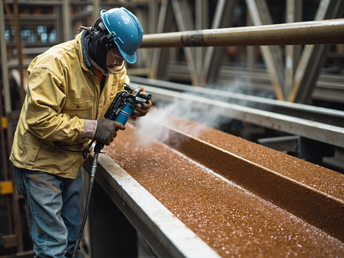
MIO intermediate coat can be formulated as solvent-based, high-solid, or even solvent-free. Solvent-free epoxy MIO can achieve a thicker film in a single pass and lower VOC, meeting the VOC limit requirements for industrial protective coating in GB 30981-2020. However, the solvent-free type demands higher requirements for two-component heated spray equipment and process, and is more sensitive to ambient construction temperature—at low temperatures the viscosity is high and it is difficult to apply. For large-volume projects with VOC restrictions (such as bridges, overall tank coating systems), solvent-free epoxy MIO is a low-VOC upgrade direction, but it requires supporting equipment and skilled workers; when selecting, one should comprehensively evaluate equipment investment and long-term compliance benefits rather than only looking at unit price.
From a full life-cycle perspective, the solvent-free solution reduces thinner consumption and exhaust treatment costs, and at the same equivalent total thickness requires fewer coats and fewer interfaces, which instead improves reliability. But it must be reminded: solvent-free does not mean "just apply thick arbitrarily"—excessive single-pass thickness still causes sagging and high internal stress, and still requires pass-by-pass control per the process card. By assessing "low VOC" and "barrier thickness" in parallel, the MIO intermediate coat can continue to serve as the main thickness layer in the green transition, rather than being displaced by low-VOC but weakly barrier products, thus preserving both environmental protection and performance.
VIII. Performance Verification and Acceptance Approach
As one link in the coating system, the MIO intermediate coat is mostly verified within the overall system; separate submission for testing often leads to misjudgment:
- Overall salt spray, cyclic corrosion: Per ISO 12944-6, the system passes the corresponding duration for C5, CX with no substrate rust;
- Adhesion: Interlayer cross-cut grade 1 (GB/T 9286) or pull-off ≥ 5 MPa (ISO 4624);
- Dry film thickness: Per the 90/10 rule of ISO 19840;
- MIO content: Supplier provides pigment specification and dry film analysis.
Conducting salt spray on the intermediate coat alone is of little significance, because it is inherently non-weather-resistant and non-decorative; its value lies in the "barrier contribution within the system" and should be judged in overall system testing. Many owners mistakenly submit the intermediate coat alone, and then misjudge it due to poor weather resistance—this is a typical test method mismatch. The correct acceptance logic is: in the overall system, see how much barrier service life it contributes; in the single coat, only check its compatibility with upper and lower layers, adhesion, and whether thickness meets the standard. Incorporating "incoming material comparison" into acceptance can block many low-quality products that pass off ordinary red iron oxide as MIO, protecting the true service life of the entire system.
IX. Common Misconception Analysis
The most common cognitive misconceptions in engineering need to be clarified one by one:
- Misconception 1: MIO intermediate coat can replace zinc-rich primer. Wrong. It has no cathodic protection; at damaged areas it does not protect steel and cannot replace the primer.
- Misconception 2: The redder the color, the higher the content. Wrong. Color is affected by particle size and surface treatment; content must be verified by testing, not by naked eye.
- Misconception 3: Thicker is better. Wrong. Excessive thickness sags and creates high internal stress; should follow the target thickness of ISO 12944-5 with controllable single pass.
- Misconception 4: Granular form is also acceptable. Wrong. MIO must remain flake-shaped; broken into particles the labyrinth effect disappears and barrier drops sharply.
- Misconception 5: Intermediate coat VOC need not be controlled. Wrong. At large usage, the total VOC of intermediate coat is considerable; high-solid and solvent-free should be prioritized to meet GB 30981.
- Misconception 6: Intermediate coat can be used exposed. Wrong. It is not weather-resistant and must be covered with a weather-resistant topcoat, otherwise it will chalk and lose gloss.
As a system supplier, Kexin New Materials (kexinMaterials) marks the MIO content and aspect ratio range on its epoxy MIO intermediate coat, and provides single-pass, total thickness, and recoat window in the process card, turning "thickening" into acceptable numbers rather than verbal promises, and facilitating supervisor acceptance by data. This practice of "writing parameters into deliverables" is exactly the first line of defense for heavy-duty anti-corrosion projects to avoid substitution of inferior for genuine products.
X. Differentiated Usage in Tanks and Bridges
The same material used differently in different parts reflects the system philosophy of "allocating thickness by environment and accessibility":
- Bridge exterior surface: MIO intermediate coat is the main thickness layer of C5, CX systems, commonly 120–160 µm, topped with polyurethane topcoat;
- Tank outer wall: C4 environment commonly around 120 µm, balancing cost and barrier;
- Tank inner wall: Solvent-free epoxy MIO can serve as a thickness-increasing barrier layer of the lining, but when in contact with media, the chemical resistance of the top layer matters more;
- Offshore platform: CX environment total DFT around 320 µm, MIO intermediate coat occupies the highest proportion and is the main force against salt spray splash.
Parts with poor accessibility and high maintenance cost (such as offshore platform splash zone, interior of cross-sea bridge box girders) should allocate more thickness to the intermediate coat, because once failed, refurbishment is extremely costly. Conversely, indoor or C3 light corrosion environments can appropriately reduce intermediate coat thickness, shifting cost to more needed parts. This differentiation is not arbitrary, but an engineering decision based on environmental grade and full-life maintenance cost.
XI. Heat Resistance and Special Variants of MIO Intermediate Coat
Standard epoxy MIO is for normal-temperature atmosphere. For temperature-resistant occasions (such as chimneys, high-temperature pipeline exteriors), there is heat-resistant MIO intermediate coat: using silicone-modified epoxy or pure silicone resin as binder, it can resist 200–400℃ or even higher, while retaining flake barrier. There is also glass flake epoxy with similar principle but stronger barrier (see comparison later). When selecting, choose binder by working temperature; ordinary epoxy MIO exposed above 120℃ long-term will thermally degrade and chalk, and cannot be forced on high-temperature parts. The heat-resistant type is common in power plants, metallurgy, petrochemical flue external protection; its underlying logic is consistent with ordinary MIO—using flake filler to extend permeation path, only the binder is changed to a temperature-resistant system so the barrier function does not fail at high temperature.
XII. Comparison with Glass Flake Coating
Glass flakes and micaceous iron oxide both belong to "flake barrier fillers", but glass flakes have larger aspect ratio, are thinner, arrange more densely, with stronger labyrinth effect and better temperature and chemical resistance, commonly used in strong corrosion linings (such as desulfurization towers, chemical tanks). Comparison:
| Filler | Barrier strength | Cost | Typical use | Application difficulty |
|---|---|---|---|---|
| Micaceous iron oxide | Medium | Low | Atmospheric system intermediate coat | Low |
| Glass flake | High | High | Strong corrosion lining | Medium–High |
The two are not substitutes but graded: atmospheric anti-corrosion uses MIO, strong media lining uses glass flake. Understanding this avoids the mismatch of "using MIO as lining" and also avoids the waste of "using glass flake as ordinary intermediate coat". In many flue gas desulfurization systems, glass flake lining replaces MIO intermediate coat to resist wet flue gas and acidic condensate, while steel structure exterior still uses MIO plus polyurethane, forming an "internal-external grading" system strategy.

XIII. Thick-Coat Sagging and Application Control Special
Although epoxy MIO is high-build, a single pass too thick (> 120–150 µm) may still sag, especially on vertical surfaces. Control measures include:
- Use high-thixotropy formula, match spray gun parameters;
- Control vertical surface single pass at 80–100 µm, target thickness can be split into 2 passes;
- Control ambient temperature, avoid high temperature reducing viscosity and worsening sagging;
- Measure wet film thickness (WFT) instantly, estimate DFT;
- At corners, edges and other easy-to-sag parts, manual touch-up must also control thickness.
Sagging not only looks bad, but also causes uneven film thickness and local premature aging from over-thin areas; it must be corrected on-site immediately, not remedied after curing. A "wet film—dry film" corresponding table should be established, so applicators can judge on the spot whether it will exceed thickness and sag, rather than finding local thin spots or sagging only by thickness measurement the next day. This instant feedback mechanism is the key to quality management of high-build coating application.
XIV. Example of System Film Thickness Allocation Calculation
Taking ISO 12944 C5 system total DFT 280 µm as example, the film thickness allocation logic:
- Zinc-rich primer 60 µm (electrochemical protection, not too thick);
- Epoxy MIO intermediate coat 140 µm (2 passes ×70 µm, bearing main thickness);
- Polyurethane topcoat 80 µm (weather-resistant, not too thick);
- Total 280 µm, meets 90/10 rule and optimizes each layer function.
If thickness is piled onto the topcoat (e.g., topcoat 140 µm), the weather-resistant layer is too thick and prone to cracking, and wastes expensive topcoat; piling onto primer causes zinc-rich cracking. The intermediate coat is designed for "safe thickening", and allocation calculation is basic skill of system design. As a system supplier, Kexin New Materials (kexinMaterials) provides target DFT and limits for each layer in the process card, letting construction follow numbers not feel. The film thickness allocation of different projects reflects the "intermediate coat main thickness" principle:
| Project part | Primer DFT | MIO intermediate coat DFT | Topcoat DFT | Total |
|---|---|---|---|---|
| Bridge exterior C5 | 70 | 140 | 80 | 290 |
| Tank exterior C4 | 60 | 120 | 60 | 240 |
| Offshore platform CX | 80 | 160 | 80 | 320 |
| Plant steel structure C3 | 50 | 100 | 50 | 200 |
The values listed in the table are typical target values; in practice, control shall be based on an upward adjustment from the minimum values of ISO 12944-5 and satisfy the 90/10 rule. It can be seen that regardless of the environmental class, the intermediate coat always accounts for about half of the total thickness—this is the quantitative proof of its role as the "thickness bearer". Write the film thickness allocation into the process card, execute construction according to the numbers, and the functional division of the system will not be distorted on site.
15. Production and Quality Control of MIO Pigment
The performance ceiling of micaceous iron oxide (MIO) intermediate coat is largely determined when the pigment enters the factory. Key quality control points for MIO pigment: flake aspect ratio (higher is better for barrier effect, commonly assessed by sieving plus microscopic statistics), flake integrity (over-grinding that breaks flakes into particles means rejection), Fe₂O₃ content and impurities (low water-soluble salts and low impurities to avoid blistering), and flake size distribution (to ensure stacking density). Suppliers should provide pigment specification sheets and batch inspection reports, rather than merely stating "MIO content".
The key at the production end is the dispersion process: it must evenly disperse the flakes and orient them parallel to each other, without grinding the flakes to pieces. Excessive high-shear dispersion time destroys the flake morphology, while too short causes agglomeration. Mature formulations balance grinding time and orientation control, and if necessary add additives to promote parallel arrangement of flakes, maximizing the labyrinth effect after curing. This is why, even with the same label of "epoxy MIO", the barrier service life from different manufacturers can differ by several times—the difference often lies in the pigment and dispersion, not the resin itself. For purchasers, listing "flake aspect ratio plus content test report" as a receiving inspection item better guarantees the true service life of the system than simply comparing prices.
16. Synergy Model: Cathodic Protection plus Physical Barrier
Understand the cathodic protection of the primer and the barrier of the intermediate coat in the same picture: the zinc-rich primer is responsible for "electrochemical protection at damaged areas", and the MIO intermediate coat is responsible for "physical delay at intact areas". When superimposed, the steel substrate gains two lines of defense—rust does not occur at pinholes and scratches (zinc), and corrosive media reach the large intact areas very slowly (labyrinth). Mathematically, the total corrosion rate is approximately the sum of the pinhole-area rate and the intact-area rate; the former is suppressed by zinc sacrifice, the latter by the labyrinth effect, and neither can be omitted.
This explains why the system must be synergized as "primer + intermediate + topcoat" rather than replaced by thickening any single layer. Piling all thickness into the primer (zinc-rich prone to cracking) or all into the topcoat (insufficient barrier, expensive) disrupts the synergy and leads to premature aging. Film thickness allocation is the mathematical manifestation of synergy and the underlying logic of the ISO 12944-5 system table. In C5 and CX high-grade systems, this synergy is fixed by the standard as mandatory division of labor; any modification that "omits the intermediate coat" will directly lower the durability grade, and owners and design units should resist such "cost reduction" proposals.
17. Key Points for Engineering Inspection and Supervision Acceptance
Acceptance of MIO intermediate coat on site should focus on three things: film thickness (according to the 90/10 rule of ISO 19840, confirm the intermediate coat bears the main thickness), interlayer adhesion (cross-cut grade 1 or pull-off ≥ 5 MPa, confirm tie coat function), and compatibility with upper and lower coats (apply within recoat window, abrade if overdue). For large-volume projects, it is recommended to retain samples from each batch for system salt spray or cyclic corrosion tests to confirm stable barrier contribution.
In addition, although color and appearance are not performance cores, they are intuitive means to judge on site "whether the correct product is used"—if the incoming material color and texture obviously differ from the sealed sample, use should be suspended and MIO content retested. Incorporating "incoming material comparison" into acceptance can block many low-quality products that pass off ordinary iron oxide red as MIO, protecting the true service life of the entire system. Be stricter in acceptance and you have one less major overhaul later—this is the simplest account for heavy-duty anti-corrosion projects. Supervisors and owners should write these acceptance clauses into the technical specification during the bidding stage to constrain suppliers from the source.
18. Quick Troubleshooting of Common Quality Problems
For intermediate coat related defects encountered on site, quick troubleshooting: poor adhesion → surface preparation or exceeded recoat interval; sagging → single coat too thick or low viscosity; blistering → substrate with water or zinc salts not removed; early rust → insufficient film thickness or falsely labeled MIO content; interlayer delamination → incompatible with topcoat or uncontrolled interval; cracking → single coat too thick or insufficient binder. Posting this troubleshooting table on site shortens fault location time and prevents suppliers from blaming construction errors on the product itself. Transparent attribution of quality problems is the premise for long-term reliability of the system and a practical tool for owners to protect their own interests, far more valuable than post-hoc accountability.
19. Storage and Construction Taboos
MIO intermediate coat is a two-component epoxy; storage requires avoiding moisture and cool conditions, as the hardener gels and fails if it absorbs moisture; after opening, use up quickly and seal. Construction taboos: ① coating on substrate with oil, water, or zinc salts not removed; ② arbitrary mixing ratio; ③ single thick coat exceeding 150 µm without sag control; ④ no abrading beyond recoat interval; ⑤ forced construction in high humidity and low temperature. Any taboo turns "good material" into "bad system". Supervisors using these five items as a checklist during patrol can intercept the vast majority of on-site mistakes; printing the taboos on packaging and process cards is the cheapest and most effective quality control for the site.
20. Green Route and Future Trends
The greening of MIO intermediate coat mainly has two paths: one is to increase solid content, moving from high solvent-based to high-solid and solvent-free to reduce VOC and meet GB 30981-2020; the other is water-based epoxy MIO, further reducing VOC, but more sensitive to construction temperature and humidity and slower drying. Neither path changes the mechanism of "flake barrier", only replacing the binder and dispersion medium with more eco-friendly ones. For large-volume bridge and tank projects, solvent-free epoxy MIO with thicker single coat and lower VOC is an upgrade direction that combines cost-performance and compliance.
Future trends also include: using finer MIO to improve flake stacking density, using additives to improve flake parallel orientation, and balancing thixotropy and workability in solvent-free systems. Regardless of how technology evolves, the core mechanism of flake barrier will not change, and the position of MIO intermediate coat as the "main thickness barrier layer" in atmospheric anti-corrosion remains difficult to replace. During green transformation, owners and design units should prioritize "low VOC and non-degraded barrier performance" solutions, rather than sacrificing barrier for VOC reduction, which equals burying premature aging risks under the name of environmental protection.
FAQ
Q: Why can micaceous iron oxide intermediate coat resist corrosion when it contains no zinc?
A: It relies on the physical labyrinth effect of MIO flakes to block corrosive media. Countless parallel overlapping flakes greatly extend the permeation paths of water, oxygen, and chloride ions, reducing the media rate reaching the steel substrate according to Fick's diffusion law. It provides no cathodic protection, but uses "lengthened permeation path" physical barrier to complement the electrochemical protection of the primer; the two are synergistic in the system and neither can be omitted.
Q: Is higher MIO content always better?
A: Not infinitely high. The content must be sufficient to form dense flake stacking (dry film MIO mass fraction about 30%–40% or above, and good flake aspect ratio) to have significant labyrinth effect; but too high causes insufficient binder, reduced adhesion, and easy cracking. A balance should be struck between barrier effect and film integrity, based on supplier tests rather than publicity, and never judge content by color shade.
Q: Can MIO intermediate coat be used as primer?
A: No. It has no zinc sacrificial anode protection, and provides no electrochemical protection for steel substrate at pinholes and scratches, where rust will occur. It is positioned as an intermediate thickening barrier layer, and must be used with zinc-rich, epoxy primer and weather-resistant topcoat, typically the "primer + intermediate + topcoat" three layers of ISO 12944. Using intermediate coat as primer equals abandoning the cathodic protection line of defense.
Q: Why is the intermediate coat often the thickest?
A: Because the safe thickness increase of total DFT mainly falls on the intermediate coat: primer (zinc-rich) cracks if too thick, topcoat should not be too thick to retain gloss, while high-build epoxy MIO can be 80–120 µm per coat, bearing about half the system thickness, with good interlayer bonding and stress homogenization. Piling thickness in the intermediate coat is most economical and reliable, which is also the common arrangement in ISO 12944-5 system tables.
Q: Is there a difference between granular iron oxide and micaceous iron oxide?
A: The essential difference is morphology. Micaceous iron oxide is flaky (high aspect ratio), producing labyrinth effect; ordinary iron oxide red is granular, serving only as ordinary pigment and filler with no significant barrier extension. Over-grinding flakes into particles also loses MIO value. Selection should look at flake proportion and aspect ratio test reports, not just the "iron oxide" composition.
Q: Does MIO intermediate coat need weather resistance?
A: No direct weather resistance needed; it lies under the topcoat and is not exposed to UV. Its value is in barrier and interlayer connection; weather resistance is handled by the upper aliphatic polyurethane or polysiloxane topcoat. A standalone exposed MIO layer will chalk and lose gloss, so it cannot be used bare and must be paired with a weather-resistant topcoat for a complete system.
Q: Is solvent-free epoxy MIO worth adopting?
A: Worth it for large-volume projects with VOC restrictions. Solvent-free epoxy MIO has thicker single coat and lower VOC, meeting GB 30981-2020, but requires two-component heated spray equipment and skilled workmanship. It is a low-VOC upgrade direction for bridge and tank high-grade systems; equipment and construction capability should be included in the evaluation.
Q: How to verify the intermediate coat truly contains sufficient MIO?
A: Require the supplier to provide pigment specifications (MIO content, aspect ratio) and dry film analysis (e.g., SEM morphology plus elemental, mass analysis), and look at its performance in overall system salt spray and cyclic corrosion tests (per ISO 12944-6). Salt spray on the intermediate coat alone is meaningless; it should be evaluated in the system, because the value of the intermediate coat is only reflected in the overall system.
Q: What happens if the recoat interval is exceeded?
A: If the epoxy MIO surface exceeds the maximum recoat interval, it may be partially cured with reduced surface energy, and direct topcoating will cause poor interlayer adhesion and whole-sheet delamination. When overdue, abrade (sweep blasting, sanding) or clean and activate before recoating, as specified in TDS and system process card. This is the most common failure mode of intermediate coat systems; supervisors must control the recoat interval.
Q: How is MIO intermediate coat used on tank interior?
A:Can be used as a thickening shielding layer for solvent-free epoxy lining, but the final chemical resistance in contact with the medium is determined by the lining topcoat; if the stored medium is highly corrosive, a dedicated lining system such as phenolic epoxy should be adopted. Here, micaceous iron oxide mainly contributes shielding thickness and cannot replace the dedicated chemical-resistant topcoat. During selection, the two roles of "shielding" and "medium resistance" must be viewed separately.
Further Reading
- ISO 12944 Anti-corrosion Coating System Selection Guide: Understand how intermediate coat thickness is allocated in the ISO 12944-5 system table, and how environmental classes determine the total DFT.
- Aliphatic Polyurethane Topcoat Weather Resistance: Above the micaceous iron oxide is the weather-resistant topcoat; the division of labor among the three determines the lifespan of the entire system. Understand why the topcoat must cover the intermediate coat.
- Epoxy Zinc-rich Primer Cathodic Protection Mechanism: Understand how the electrochemical protection of the base layer synergizes with the shielding of the micaceous iron oxide intermediate coat, forming a dual defense line of the system.
- Epoxy Micaceous Iron Oxide Intermediate Coat: Micaceous Iron Oxide Flake Shielding Mechanism and System Design
- Anti-corrosion Coating Specification for Bridge Steel Structures
- Alkyd Anti-rust Paint: Iron Oxide Red/Gray Anti-rust, Application Characteristics and Limitations