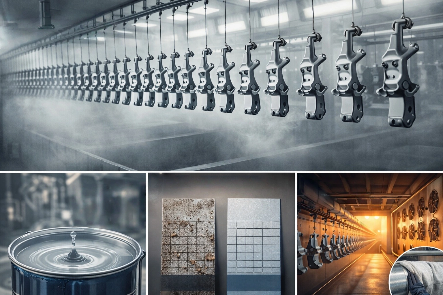
A paint-free zone on a frame or chassis part - also called a coating hold-off area, and on some drawings a mask-off or keep-off area - is a surface region on a frame rail, cross member, bracket, suspension seat, or welded chassis assembly that the drawing explicitly declares uncoated, or from which the coating must be locally removed after painting, so that grounding contacts stay conductive, assembly fits stay in band, threads stay assemblable, and later repair welding stays possible. It is one of the few design items in an electrodeposition system where doing less costs more: the film that wraps the whole part also wraps the conductive faces, the mating faces, and the internal threads.
A tractor plant saw it play out on the final assembly line with a whole build group: the harness grounding bolts on the frame were tightened to the drawing torque, static voltage checked out, and after roughly three hundred kilometres the instrument panel started alarming and the charging lamp flickered. The ground strap came off showing a full, intact cathodic e-coat film on the contact face - metal had never actually touched metal. A milliohm meter put the circuit resistance in the 10 Ω range, while unpainted parts from the same batch measured under 0.3 Ω. The rework was bolt-off, scrape the contact face, re-measure, reinstall: 25 extra minutes of labour per vehicle, and the scraped-bright patches flashed rust within three months. Pretreatment and e-coat parameters were all in specification, because the fault was never in the paint - it was that a paint-free zone had never been defined.
TL;DR: six conclusions you can paste into a technical agreement
- Cathodic e-coat typically runs 18-25 μm dry film, a process band of 15-35 μm, and a cure window of 170-180 ℃ held for 20-30 min; that film thickness and temperature window decide together whether conductive faces survive and whether masking hardware lives through the oven.
- Grounding circuits are commonly specified at a circuit resistance no higher than 0.5 Ω (re-measuring with a four-wire method is the steadier reading), and a continuous e-coat film is an insulator; holiday detection finds pinholes at all - ASTM D5162 low-voltage wet sponge applies to total dry film thickness up to 0.5 mm - precisely because the coating does not conduct.
- Bolted joints typically lose 5%-18% of preload to interface embedment; on the VDI 2230 basis of 1-7 μm per interface, adding the paint film and any soft plating can stack tens more micrometres of settlement - under identical geometry an M12 joint loses about 12%, an M4 joint up to 38%.
- Internal threads need their own verdict: 15-35 μm of deposited film interferes with thread engagement on fine-pitch holes and bores below M4, and only three routes exist - mask before the dip, re-tap after the coat, or reopen the tolerance for the coating build.
- The paint-free-zone list can borrow the "hold-off area" scope of CB/T 3798-2016 and T/CANSI 42-2020 directly: at least 50 mm each side of weld lines, bolt and pin holes, hinge-pin mating surfaces, sealing faces, flange contact faces, grounding and conductive contact faces, nameplate bosses, and stop or locating faces.
- GB/T 3273-2026 (hot-rolled steel plates and strips for automobile frames) took effect 2026-10-01, replacing GB/T 3273-2015: thickness raised to a maximum of 18.0 mm, P no higher than 0.020%, S no higher than 0.012%, 700L grade with ReL at 600 MPa minimum and Rm of 700-880 MPa; the thinner and stronger the frame steel gets, the dearer a wrong hold-off area becomes to rework.
The boundary of a paint-free zone: three classes of surface, not one masking sketch
Reading a paint-free zone as "where the shop sticks the tape" is the common misjudgement. It is actually the union of three classes of functional surface; each class has its own failure mode, its own acceptance criterion, and its own remedy, and merging them into one list guarantees omissions.
Class 1 is conductive surfaces: ground studs and earth points, shield terminations, mounting faces for motors and controllers, sensor mounting datums. They fail as excess resistance, and the criterion is a milliohm or ohm reading.
Class 2 is locating and mating surfaces: suspension bushing bores, leaf-spring seat faces, axle-housing mating surfaces, hinge-pin bores, dowel locating faces, sealing flange faces. They fail as assembly clearance, coaxiality, or seal squeeze-out of specification, and the criterion is dimension and force.
Class 3 is process surfaces: weld preparations and the band each side where welding happens after painting, threaded holes assembled only after coating, datum faces for labels or engraving, and stop or locating faces that must remain separable. They fail as welds that will not fuse, taps that will not start, lost markings - and the criterion is simply whether the next operation can proceed.
One technical root underlies all three classes: electrodeposition immerses the whole part, is field-driven, and is self-limiting in thickness; it does not voluntarily pass up any bare metal. The film it leaves behind is, at the same moment, a missing conductor, a dimensional add-on, and a welding barrier.
Why conductive failure is inevitable: coating insulation is the premise of every acceptance method
Cathodic e-coat resin deposits by reduction at the cathode as the interfacial pH rises, and the crosslinked epoxy network that follows does not conduct. Precisely because this continuous film is insulating, pretreatment and deposition quality can be verified electrically: a pinhole, crack, or crater lets the probe current reach the substrate and the instrument alarms. The scale the industry reads against is ASTM D5162: low-voltage wet sponge for coatings with a total dry film thickness up to 0.5 mm (20 mil), high-voltage spark for coatings above 0.5 mm; coatings between 0.25 mm and 0.5 mm may also be tested with high-voltage equipment provided the test voltage is calculated from film thickness and dielectric strength and the coatings supplier approves. A chassis e-coat film of 18-25 μm sits inside the wet-sponge range - which also means 100% in-line holiday testing is an executable quality gate, not a laboratory idea.
For a ground contact, the very same film means an insulator 18-25 μm thick standing between the faces: even when the bolt clamps the two parts together, true conduction rides on the handful of points where the film is crushed through. If the film is not pierced, circuit resistance jumps from a fraction of an ohm to tens of ohms. Shop-floor rules such as "never land a ground at the painted station" or "grind the earth point before bolting" are all paying this bill after the fact.
Three routes to conductive surfaces: masking, post-coat film breakdown, paint-piercing fasteners
The industry has only three routes for conductive faces. The trade-off between them is never conductivity itself - all three pass the grounding test - but corrosion loss, takt cost, and consistency risk.
Route one is masking before the dip: process bolts pre-installed into the welded nuts, high-temperature masking tape, or silicone masking caps and plugs. Process bolts restore conduction immediately and predictably, at low cost, and they can be reused; the price is that the masked zone stays bare and forms a crevice. Degreaser and phosphating solution still wick along the narrow gap and strip the rust-preventive oil the steel mill left on the sheet, the rinse station cannot flush the trapped liquor out, and the faying face corrodes very quickly - a field comparison showed visible rust inside one week - after which conductivity degrades again. That is the fate of almost every masking-only scheme.
Route two is breaking the film after coating: grinding, scraping, or re-tapping. The corrosion penalty is small (the coat stays intact except at the contact point) and conduction is reliable, but it depends on operator feel, slows takt, is easy to skip, and the freshly bared face must be touched up on the spot or covered with conductive paste.
Route three is designing the function into the commodity part: paint-piercing ground studs and nut assemblies. Published designs include a bolt with three evenly spaced relief slots milled near the thread run-out plus symmetrically pressed annular ribs - press marks about 0.3 mm deep, 5 mm long, and 1.5 mm wide - paired with a washer-and-spring-washer assembly; other versions roll six helical lines into the thread so the profile deforms the film microscopically; castle-nut assemblies serve the same purpose. This route hands consistency to the stamping and fastener supply chain, and the paint shop needs no special operation for ground points.
| Item | Pre-dip masking (process bolts/tape/silicone caps) | Post-coat film breakdown (grinding/scraping/re-tapping) | Paint-piercing standard parts |
|---|---|---|---|
| When conduction returns | At assembly, immediately | Via a post-coat operation | Automatically during tightening |
| Corrosion state in the masked zone | Bare metal; crevice liquor accelerates rust (field comparison showed week-scale corrosion) | Coat intact except at the contact point | Coat intact; local film break only at the press ribs |
| Takt and labour dependence | Install and remove masking, moderate labour | Heavy manual work, weak consistency | Low labour, depends on incoming-part consistency |
| Key dimension or condition | Must survive the 170-180 ℃ oven | Leave a 5-10 mm margin around the contact area when breaking the film | Press marks about 0.3 mm deep, 5 mm long, 1.5 mm wide |
| Typical failure | Masked zone rusts, contact resistance climbs back | Skip or over-grind, scoring the substrate | Cripple pressing or wrong part, a whole batch out of limits |
Mating surfaces and locating bores: the film eats the tolerance band, not the appearance
Chassis and frame parts datum almost everything from bores and faces. Dowel pin bores, bushing mounting holes, leaf-spring seat faces, axle-housing mounting faces, propshaft flange faces - once the e-coat covers them uniformly, the nominal dimension is gone. The magnitude is not vague: 18-25 μm per side, and when hole and shaft are both coated the radial build-up is 36-50 μm.
Put that number on a tolerance table and the picture is blunt. A ⌀12 mm H7 bore carries a tolerance band of +18 μm with zero lower deviation; a ⌀10 mm H7 bore carries about +15 μm. After a locating pin bore and the pin itself each deposit 18-25 μm of e-coat, the interference already exceeds the whole width of the H7 band and the pin will not enter. This is not a matter of pressing a little harder: forcing it shears the coating and opens a delamination path at the interface, and rust starts at exactly that point.
Only four remedies exist, in ascending cost: declare the bore paint-free and mask it with a silicone plug or process pin before the dip; keep the coating but re-proportion the machining size of the hole for the coating build (machine oversize first, then coat); finish mechanically after coating - ream, bore, or scrape; or change the process sequence, dropping the part from full-assembly dip coating to component coating followed by assembly.

Edges and hole mouths are the other face of the same problem. Electrodeposition distributes film unevenly at sharp edges and bore mouths: edges run thin while hole entries pool and stack thick, so a tolerance opened on nominal film thickness does not hold on the real part. Acceptance therefore cannot rest on a single spot reading. The working convention is the 90-10 rule: 90% of measurement points no lower than the specified thickness, the remaining 10% no lower than 80% of the specification, and the low readings must not cluster in one area; measurement density is set by location, with no fewer than 3 points per small part, and thickness is read with an eddy-current or magnetic-induction gauge (methods of the GB/T 4957 type).
Faying surfaces are more than dimensions: sealing and clamp-up are rewritten by film thickness too
Fuel-tank straps, air-filter housing mounting faces, flanged tube-clamp seats - any face that must hold seal pressure - suffer a "soft" effect from the coating: the paint film creeps and embeds under sustained pressure, initial squeeze looks sufficient, and after a period in service the joint relaxes and the sealing pressure decays. The design decision belongs in the technical agreement: either put the face in the hold-off area with local rust prevention, or isolate the sealing surface with a gasket - rather than trusting the flatness of a coating.
The second boundary that runs along faying faces is friction-type connections. Structural bolting already has an explicit criterion: the slip factor is tied to the coating system, and a faying surface cannot simply be painted; see Can high-strength bolt faying surfaces be painted: slip-factor values and re-verification. The reading logic is identical on chassis parts, except the governing numbers come from the OEM technical conditions and measured slip loads instead of structural codes - the two sets must never be interchanged.
Threaded holes and fine pitch: 15-35 μm is enough to stop an assembly line
Electrodeposition's effect on threads is chronically underestimated. The self-limiting film deposits uniformly on flanks and roots of internal threads, eating the usable clearance from both sides at once. On coarse-pitch holes such as M10 and M12, a post-coat re-tap - or driving the bolt in - remains workable and the process cost is controlled; on fine-pitch threads, thin-wall bosses, and holes of M4 and smaller, re-tapping tends to pull whole turns of thread out, and only pre-dip masking is a safe answer.
Masking hardware for small threaded holes must survive two different environments: the temperature and pH of the degreasing and phosphating baths, and then the cure stage at 170-180 ℃ held for 20-30 min. Ordinary PVC plugs and low-temperature tape deform, char, or leave adhesive behind. The industry standard is high-temperature silicone masking caps and plugs paired with polyester-class temperature-resistant tape. When a masking part fails inside the oven, the residue contaminates the internal threads and the bath at the same time, and the cost dwarfs the masking itself.
One masking detail deserves the operator instruction: peel the tape after the topcoat has dried touch-dry. Peeling early tears the wet film; peeling late, once the coat is fully cured, lifts coating at the edge of the hold-off area. After removal the hold-off zone must show no adhesive residue and no coating contamination. The peel-force window and temperature-versus-dwell behaviour on the refinish side are covered in Refinish masking: peel-force window, bake dwell, and edge pull-in control.
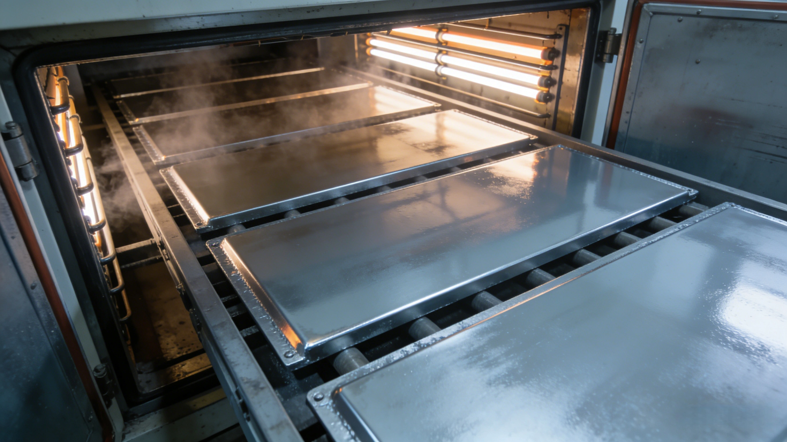
The boundary that gets forgotten is "parts that cannot see the oven." A chassis assembly carries polyurethane bushings, rubber mounts, plastic clips, and installed harness sleeves whose temperature ceilings sit below the e-coat cure window, so painting of frame and suspension parts must precede their assembly. If the customer drawing demands painting the finished assembly, the cure window must drop to a low-bake system at 150-160 ℃, and the bushing supplier's temperature declaration governs.
Writing the paint-free-zone list: borrow the proven "hold-off area" scope
Shipbuilding has already standardised this. CB/T 3798-2016 (technical requirements for painting of steel ship outfitting components) and its companion T/CANSI 42-2020 (paint hold-off requirements for ship outfitting components) define the scope of a "coating hold-off area" and it lifts straight into a template for truck and off-highway chassis parts: weld preparations and areas awaiting welding (no less than 50 mm each side of the weld line), bolt holes and pin holes, hinge-pin mating surfaces, sealing faces, flange contact faces, sleeve faces at penetrations and 50 mm of wall each side, grounding and conductive contact faces, stainless and dissimilar-metal contact faces, engraving and marking faces, nameplate bosses, and stop or locating faces. The same scope adds: hold-off areas must be clean and masked before painting, a shop primer may be pre-applied where necessary with film thickness held at 15-25 μm and no more than 30 μm.
Execution on commercial vehicles differs in three places: conductive faces must additionally state the permitted film-breakdown method; mating faces must name the post-coat finishing operation and the gauge; and every hold-off area must carry its own corrosion-protection alternative - because each line on the list is a patch of bare metal.
| Class | Typical locations | What the drawing must state | Measures beyond the coating |
|---|---|---|---|
| Conductive faces | Ground-strap contact faces, shield terminations, motor and controller mounting faces | Bare area, permitted film-breakdown method, circuit-resistance limit (0.5 Ω on the engineering convention) | Conductive paste, toothed lock washers or paint-piercing fasteners; rust-preventive touch-up at the edges |
| Locating and mating faces | Dowel bores, bushing mounting holes, axle-housing and seat contact faces, flange faces | Post-coat reaming or boring, gauge inspection, 36-50 μm allowance for two-sided build-up | Local rust-preventive oil or removable protective coating after assembly |
| Threads and pin holes | Fine-pitch holes, holes of M4 and smaller, hydraulic port threads | Silicone plug masking or post-coat re-tapping; state that forced entry is prohibited | Clear chips after re-tapping and seal with touch-up |
| Welding and process faces | At least 50 mm each side of repair weld preparations, faces assembled after painting, engraving and nameplate bosses | Reserved band width, tape-peel timing, zero-adhesive-residue requirement | Post-weld touch-up system matched to the original system |
| Dissimilar-metal interfaces | Aluminium brackets onto steel frames, stainless fastener seats | Isolation method for the bare face, so a broken coating edge does not accelerate galvanic attack | Insulating washers, sealed edges; see galvanic-corrosion protection design |
| Coating system | Typical single-side DFT | Hole-and-shaft two-sided build-up | Fit judgement |
|---|---|---|---|
| Cathodic e-coat (CED) | 18-25 μm | 36-50 μm | Exceeds the +18 μm band of a ⌀12 H7 bore; locating bores must be masked or finished after coating |
| Waterborne dip (hardware) | 25-40 μm | 50-80 μm | Design threads and bushing bores for masking |
| Powder coating | 60-120 μm | 120-240 μm | Mating faces essentially cannot be coated; Faraday shielding also stacks thickness at bore mouths |
| Zinc flake coating | 5-15 μm | 10-30 μm | Thin with controllable friction; standard on fasteners and spring-type clamps |
| Hot-dip galvanising (ISO 1461 basis) | 45-85 μm by steel thickness grade | 90-170 μm | Two-sided build-up far beyond common bore tolerances; a duplex system with e-coat must be re-calculated |
| Shop primer (pre-coat on hold-off areas) | 15-25 μm, maximum 30 μm | 30-50 μm | Temporary rust prevention only; treat per the system requirement before main coating |
Bolted joints: the coating turns tightening torque into uncertain clamp force
The item most often missing from the paint-free-zone list is the bearing face under the bolt head and the nut. A coating there causes two independent problems: the coefficient of friction changes, and the coating embeds under pressure, adding extra relaxation.
The friction side is quantified by standard testing. ISO 16047:2005 (Fasteners - Torque/clamp force testing), adopted identically in China as GB/T 16823.3-2010, defines test conditions for bolts, screws, studs, and nuts from M3 to M39 with property classes per ISO 898-1, ISO 898-2, or ISO 898-6, and reports the torque coefficient K (K = T/(F·d)), total friction coefficient μ_tot, thread friction coefficient μ_th, and bearing-surface friction coefficient μ_b. Tester accuracy is specified at ±2%, angular measurement at ±2° or ±2%, whichever is larger; standard-condition tests run at 10 ℃ to 35 ℃ using the prescribed HH or HL bearing plates. K is reusable only under the same friction condition, the same nominal diameter, and the same geometric proportions - which is exactly why a coated fastener pair must be retested.
The relaxation side has a name: embedment (settling). Interfaces are made of asperities in micro-contact, so real contact area is far below the apparent area; when the asperities crush plastically, the grip length shortens and bolt elongation drops with it - preload falls with no rotational loosening whatsoever. Published engineering figures give 1-7 μm per interface, banded by roughness: below Rz 10 μm, about 3 μm at the thread interface, 2.5 μm per bolt-head or nut face, and 1.5 μm per inner faying face; at Rz 10-40 μm, about 3 μm, 3 μm, and 2 μm; at Rz 40-160 μm, about 3 μm, 4 μm, and 3 μm (under shear loading the numbers rise, and 4.5-6.5 μm is allowed under the head and nut). A plain steel double-plate joint at moderate roughness settles about 11 μm in total; preloading an M10 to 75% of yield loses roughly 13%, and the general loss band for metal joints is 5%-18%.
Coatings and platings make it worse: a thick soft paint film extrudes from under the bearing face and by itself can add tens of micrometres of settlement on one side alone. The fractional loss climbs steeply as diameter shrinks - embedment displacement barely scales with bolt size, while preload scales with stress area, roughly with the square of diameter - so the published calculation gives about 12% loss for M12 and about 38% for M4.
| Condition | Thread interface | Bolt head / nut face (each) | Inner faying face (each) | Consequence |
|---|---|---|---|---|
| Rz below 10 μm, axial load | 3 μm | 2.5 μm | 1.5 μm | A plain steel joint sits at the low end of 5% loss |
| Rz 10-40 μm, axial load | 3 μm | 3 μm | 2 μm | Double-plate joint totals about 11 μm; M10 about 13% |
| Rz 40-160 μm, shear load | 3 μm | 6.5 μm | 3.5 μm | Rough blast profiles and stacked edge build-up push losses upward |
| Coated or soft-plated bearing face | Film extrusion can stack tens more micrometres of settlement per side | Small-diameter joints approach the M4 level of 38% | ||
| Settlement over service time | About seventy percent of total loss occurs within roughly 30 days | The early re-check matters more than distant maintenance | ||
Design-side compensation has quantified bases as well: under the VDI 2230 stiffness allocation, the clamped members of a steel joint typically carry 3 to 6 times the bolt stiffness, so only 15%-25% of external load reaches the bolt, and preload is usually set at 70%-90% of proof load. Where a hold-off area cannot be deleted, the viable moves are fewer interfaces, bearing faces moved into the hold-off area with controlled roughness, or Belleville washers to make the grip more elastic. Published long-term estimates - roughly 10% relaxation at 50 years for a plain-washer joint versus roughly 27% for a Belleville-washer joint - show the disc spring is not a linear win over the long term and must be verified joint by joint. On commercial vehicles the familiar answer is the wheel-bolt one: schedule a re-torque window after initial mileage.
Where the joint also needs controlled friction, the route is a solid lubricant rather than leaving paint under the bearing face; the mechanism and the torque-coefficient verification are in MoS2 dry-film lubricant coating: friction mechanism, failure boundaries, and torque-coefficient verification.
The cost of bare metal: every paint-free zone must carry its own corrosion protection
Each line on the hold-off list is bare steel. On the ISO 12944-2 environment-class basis, first-year corrosion loss for low-carbon steel is greater than 25 up to 50 μm in C3, greater than 50 up to 80 μm in C4, and greater than 80 up to 200 μm in C5; zinc under the same convention loses 0.7-2.1 μm in C3, 2.1-4.2 μm in C4, and 4.2-8.4 μm in C5. In other words, a bare ground face in C4 can consume more steel in one year than the entire e-coat film is thick - while the same environment eats only a few micrometres of zinc. A paint-free zone is not "a little less paint"; it places one point into a completely different corrosion-rate regime.
Paired protection therefore comes down to four options, and all of them belong on the same drawing: removable rust-preventive oil or long-life grease that acts as soon as the part is assembled; local touch-up with ramped-over edges and adhesion re-verified by the pull-off test - reading conventions in Adhesion acceptance by pull-off: numerical judgement and failure modes; cavity wax for enclosed sections - inner-film build and criteria in Automotive cavity wax: internal coating, film judgement, and long-term protection; and insulating washers plus edge sealing at dissimilar-metal joints to break the galvanic couple, see Steel-aluminium bodies: galvanic corrosion, coating isolation, and edge sealing.
Cleaning before touch-up has hard criteria too. Hold-off areas sit in shop storage and are re-contaminated; soluble salts are a common root cause of touch-up failure, and sampling and conductivity limits follow Soluble salt contamination on substrates: Bresle sampling, conductivity limits, and judgement. After blast cleaning, the wait before primer stays within 4 h by published convention, shortened to 2 h at high humidity or near the dew point; steel temperature must remain at least 3 ℃ above dew point and relative humidity no higher than 85%.
Key data: eight quotable lines
- Cathodic e-coat typically 18-25 μm dry film, adjustable within a 15-35 μm process band; published data put achievable thickness control at ±3 μm.
- Cure window 170-180 ℃ held for 20-30 min; the broader conventional specification band is 177-204 ℃ held for 10-20 min; low-bake systems reach down to 150-160 ℃.
- Bath solids are normally held at 18%-22%; line voltages on full-vehicle dipping typically run 200-300 V, material utilisation approaches 100%, and ultrafiltration recovery exceeds 99%.
- Interface embedment on the published basis is 1-7 μm per interface, about 11 μm for a double plate with bolt and nut, and preload loss usually lands in 5%-18%.
- Torque/clamp-force testing follows ISO 16047:2005 (GB/T 16823.3-2010), covering M3 to M39, with tester accuracy ±2% and standard conditions at 10-35 ℃.
- The engineering convention for bonding and grounding criteria is circuit resistance no higher than 0.5 Ω, harness loop resistance about 0.5 Ω/m or less, and contact-resistance change no greater than 10 mΩ after vibration testing.
- Shop primer may pre-coat hold-off areas at 15-25 μm with a 30 μm cap; reserved bands at weld areas and penetration contact faces are laid out at no less than 50 mm.
- Neutral salt spray durability: cathodic e-coat commonly 500-1000 h and above, published cathodic epoxy systems reach the 1200 h class, anodic e-coat mostly 400-600 h.
Verification and acceptance: three gates plus one record set
Whether the paint-free zones were done right is not decided by looking. Gate one is conductivity: measure the grounding circuit's contact resistance with a milliohm meter (four-wire method) in the as-assembled state, with limits set by the OEM technical conditions - the engineering convention is no higher than 0.5 Ω; where conductive parts sit near drive systems, published competition rules give 300 mΩ or less as a stringent reference. Gate two is dimension: locating bores are checked with post-coat gauges, 100% or by sampling plan, and trial-fitted pins are entered by hand force only - no tools beyond human leverage - with finishing cuts logged after assembly. Gate three is the coating body: thickness judged by the 90-10 rule, hold-off edges touch-up-tested for adhesion and pinholes, with low-voltage wet sponge the right holiday tool for this thin-film class.
Record elements: making the paint-free zone traceable
The retained record should include: masking materials and their temperature declarations, the actual oven temperature curve, the stations and operators that broke the film or re-tapped, conductivity re-test readings with instrument IDs, post-coat finishing cuts with gauge IDs, and the batch and application time of every corrosion-protection measure on a hold-off area. Paint-free-zone disputes are almost never about whether the zone should have existed; they are about what was actually done at the time - and with no record, responsibility cannot be assigned.
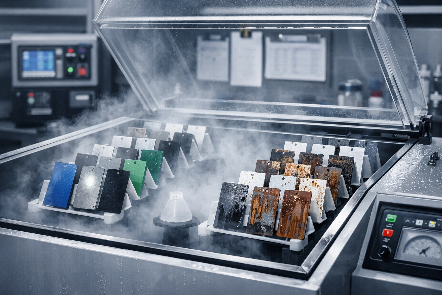
Implementation: six actions from drawing to first article
- Step 1: audit the part drawings by the three surface classes (conductive, mating, process) and tag every location as hold-off, finish-after-coat, or coat-permitted - a list, not a tape sketch.
- Step 2: put two-sided film build into the tolerance calculation, taking 18-25 μm per side on hole and shaft, and any location where the build exceeds the bore tolerance goes onto the list.
- Step 3: verify the oven window against the temperature limits of non-metallic materials on the part; at the 200 ℃ class, rubber bushings, plastic clips, and installed harnesses all have to be considered.
- Step 4: select the masking hardware - silicone plugs, temperature-resistant tape, process bolts - and validate it for release and adhesive residue against the measured 170-180 ℃ oven profile.
- Step 5: assign each hold-off area its corrosion-protection alternative and touch-up system, stating edge ramp-over and the re-test method.
- Step 6: accept the first article through all three gates, then write the conductivity readings, finishing cuts, and thickness data back into the technical agreement for reuse in volume production and successor models.
FAQ: common questions on paint-free zones for frames and chassis parts
Can we coat everything and simply grind the ground points at assembly?
You can, but price it as a process. Post-coat film breakdown carries a small corrosion penalty - only the contact point is destroyed - while takt and consistency hang on operator performance, and a skipped or overdone spot becomes excess resistance or a scored substrate. In high-volume work, paint-piercing ground studs with pressed ribs or rolled helical lines hand consistency to the fastener supply chain; in one-off and small-batch work, grinding plus conductive paste is the economical answer, but the bared face must receive rust prevention on the spot.
Why does a ground nut masked with a process bolt rust within a week?
Masking blocks the e-coat film; it does not block the pretreatment chemistry. Degreaser and phosphating solution still wick along the narrow crevice between bolt and sheet and wash off the mill-applied rust-preventive oil; the gap is too tight for the rinse station to flush the residue out, the trapped liquor bakes and accelerates attack in the oven, and the location has no coating at all against ambient air. Those three effects stack until the masked faying face shows rust within days, and conductivity degrades again right behind it - which is why a masking scheme must ship with a post-coat rust-prevention pairing.
Why must a painted fastener pair be re-tested for its torque coefficient?
The film changes both the bearing-surface friction coefficient and the embedment settlement at the same time. Under ISO 16047, K and the friction coefficients are valid only for one friction condition, one nominal diameter, and one geometric proportion - and coating is a new friction condition. Embedment displacement barely shrinks with bolt size, so the same settlement in micrometres converts into a much larger preload loss on small diameters; the published calculation reaches about 38% on an M4. Torquing a coated pair from the unpainted fastener table can leave actual clamp force far from design with no loosening signature to find it.
Shouldn't a paint-free zone be as small as possible?
No. Too small, and the film-breakdown area is insufficient: conduction hangs on a few accidentally pierced points and batch variation is wide. Too large, and the entire corrosion burden shifts onto post-paint and assembly operations. Size the zone by function: conductive faces fully expose the contact ring band, mating faces leave clearance for the finishing tool's travel, weld areas follow the process spec (commonly no less than 50 mm), and the same drawing states the temporary and long-term rust prevention for the bare area.
Can the e-coat film serve as the only topcoat on chassis parts?
Depends on exposure. Cathodic epoxy e-coat protects inner sections and non-exposed parts adequately, but epoxy coatings degrade and chalk at the surface under ultraviolet light, so exposed parts need a paired topcoat. Truck bodies and trailers - sites of both ultraviolet exposure and stone chipping - require a separate thick-film system chosen for chip and abrasion resistance. A bare e-coat exposed to long-term sun on chassis brackets will show appearance decay and film loss together.
How bad is the fallout when a small-hole mask fails?
Once a masking part chars or deforms in the oven, adhesive residue and carbonisation sit inside the internal threads: at assembly the tap or bolt bottoms out without tightening, forced entry shears the coating, and a corrosion path opens from the thread root; shed fragments also foul the bath filtration and ultrafiltration loop. Silicone plugs and temperature-resistant tape should therefore be validated against the measured oven profile, and their replacement interval and batch history folded into the bath management file.
How do you balance paint-free zones against the vehicle's corrosion-life target?
Calculate the two criteria separately. The coating side is paired to the ISO 12944-1 durability classes - low up to 7 years, medium 7-15 years, high 15-25 years, and very high beyond 25 years; the bare side is estimated from that class's first-year corrosion rate (low-carbon steel greater than 50 up to 80 μm in C4, greater than 80 up to 200 μm in C5) to size the combination of preventive oil, touch-up, cavity wax, or insulating seal. Doing only the first yields a part that passes resistance and rusts inside a year; doing only the second yields a car with sound corrosion protection and out-of-spec grounds. Both must land in the technical agreement.
References and basis of the figures
- ISO 16047:2005, Fasteners - Torque/clamp force testing; identical Chinese adoption GB/T 16823.3-2010 (Fasteners - Torque-clamp force test).
- VDI 2230 calculation method for highly loaded bolted joints and its interface-embedment values (compiled from published engineering data, including the 1-7 μm per interface band and the Rz table).
- CB/T 3798-2016 (technical requirements for painting of steel ship outfitting components) and T/CANSI 42-2020 (paint hold-off requirements for ship outfitting components): definitions and scope of the coating hold-off area and masking practice.
- ISO 12944-1 and ISO 12944-2 on durability ranges and corrosivity categories (first-year corrosion loss for low-carbon steel and zinc); the 2017 revision merged C5-I and C5-M into C5 and added CX.
- ASTM D5162 on discontinuity (pinhole) detection: low-voltage wet sponge for total dry film thickness up to 0.5 mm, high-voltage spark for coatings above 0.5 mm.
- GB/T 3273-2026 (hot-rolled steel plates and strips for automobile frames), issued 2026-03-31 and effective 2026-10-01, replacing GB/T 3273-2015: thickness ceiling, P and S ceilings, 700L together with 750L and 800L properties and impact agreements; weldability assessed via the Pcm formula.
- E-coat film thickness, cure temperature, bath solids, and salt-spray durability figures come from published process literature and supplier technical notes; the specific grade and line remain governed by the coatings supplier's technical data sheet.
- Circuit resistance up to 0.5 Ω, loop resistance up to 0.5 Ω/m, contact-resistance change up to 10 mΩ after vibration, and up to 300 mΩ near drive-system conductive parts come from published engineering and OEM technical-condition literature; they are criterion references, not a specific vehicle standard.
- Journal and conference material on embedment loss: Gradjevinar 2021, Vol. 73, No. 5 (doi 10.14256/JCE.3157.2021), which reports the finding that about seventy percent of loss occurs within 30 days and the Belleville-washer comparison.
- All coating systems, masking hardware, and rust-prevention pairings in this article are addressed in an industrial B2B supply context; trade terms are on an EXW / FOB basis for industrial supply and assembly delivery, not retail distribution.
Last updated: 2026-11-05
Kexin New Materials (Guangdong) Co., Ltd. - technical and supply support in cathodic e-coat, waterborne dip, powder, and functional coatings for commercial-vehicle and off-highway OEMs and their tier-one suppliers; technical agreements, first-article validation, and batch traceability are handled project by project on an EXW / FOB supply basis.