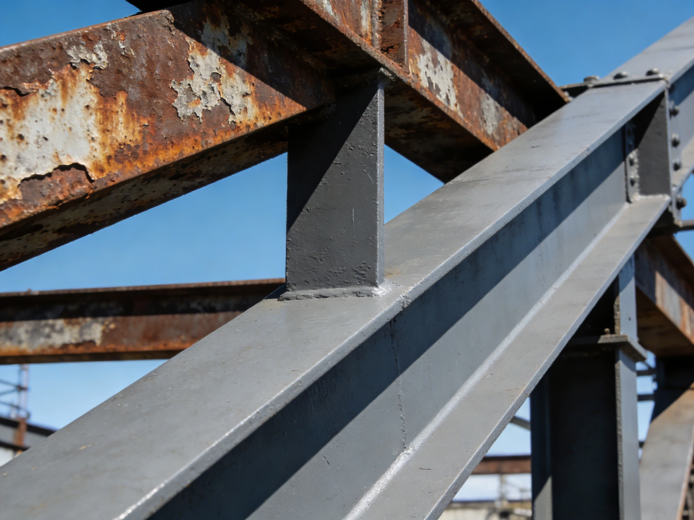
Crevice corrosion is localised attack inside a liquid-holding gap on a metal surface: at lap joints, under gaskets, around bolt holes, at weld roots and lack-of-fusion gaps, where the liquid cannot circulate or refresh. Dissolved oxygen inside the gap is consumed and not replenished, so the gap and the exposed surface form an oxygen concentration cell, the interior becomes anodic, and a self-catalytic cycle of falling pH and chloride accumulation follows. For painted steelwork the damage is not general thinning: the site is hidden, cannot be inspected and cannot be recoated.
The same picture recurs on site: the exposed topcoat is still sound, adhesion and film thickness pass, yet rust blisters and yellow streaks appear all round a lap plate, and only after the clamp is removed can the faying surface be seen to have lost thickness. Box beams take rain through their vent holes, condensation forms at night, and the rust layer inside is thicker than outside. The root cause usually sits in the geometry on the drawing, not in the paint system: a gap exists, water cannot leave, the gun cannot reach, and the gauge cannot reach either. ISO 12944-3:2017 places these issues in the design stage, as a requirement in its own right alongside environmental classification (Part 2), surface preparation (Part 4) and protective paint systems (Part 5).
TL;DR: the conclusions first
- ISO 12944-3:2017 (published 2017-11, replacing the 1998 edition) puts accessibility, gap treatment, water retention, surface imperfections, bolted connections, box members, notches, stiffeners and galvanic protection into basic design clauses 5.2 to 5.10, supported by Annexes A to D on tool space, opening sizes, narrow gaps and drainage features.
- Lap joints should be closed all round by continuous welding; intermittent welding and tack welding leave openings between segments that take water in, cannot drain it and block the spray gun. The 2017 edition adds requirements for gap filling and sealing materials in 5.3.
- ISO 8501-3:2025 (issued 2025-08-31, replacing the 2007 edition) defines three preparation grades for welds and edges, P1, P2 and P3; public interpretations recommend P2 or P3 from C4 upwards, with cut edges radiused to a minimum of 2 mm.
- The inside of a crevice is a film-thickness blind zone: coating is drawn in and flows out again, so a passing flat-surface reading does not prove design dry film thickness in the gap. Stripe coat or prime first, then spray the assembly.
- A sealant is not an anticorrosive coating: it only stops water and salt entering the gap, while dry film thickness and durability class remain the responsibility of the paint system, and compatibility and recoatability with the topcoat must be verified.
- The ferric chloride procedure in ASTM G48-25 (6 % solution) assesses crevice corrosion initiation, not propagation, and cannot be extrapolated to chloride-free environments; passing a salt spray test says nothing about the safety of a lap joint.
Why crevice corrosion fails first inside a coating system
General corrosion thins a surface evenly, so it can be planned against film thickness and service life; pitting initiates where a passive film breaks down locally on an exposed surface. Crevice corrosion differs because geometry drives it. Once a gap forms, its dissolved oxygen is consumed by the cathodic reaction, and because the opening is too narrow for oxygenated liquid to be drawn back in, the interior and the exterior form a concentration cell that makes the inside anodic. Metal ions accumulate in the crevice, chlorides migrate in to keep charge balance, metal chlorides hydrolyse to form acid, and the lower pH accelerates further dissolution. Once that self-catalytic chain is established it can keep running at potentials below the pitting initiation potential. In engineering terms, metal loss concentrates at one spot on a faying surface, stays invisible, and is found only when a seal fails or section loss affects capacity.
Oxygen depletion, pH drop and chloride build-up
The same system performs very differently depending on geometry. Inside a crevice the surface stays wet, warms slowly and concentrates salts, so the coating sits in contact with electrolyte until water uptake equilibrium is reached, adhesion falls and blisters form; at the crevice mouth the part goes through wet-dry cycling that keeps importing salts without exporting them. ISO 12944-2:2017 classifies environments by first-year thickness loss of low-alloy steel: C3 at 25 μm to 50 μm, C4 at 50 μm to 80 μm and C5 at 80 μm to 200 μm, with zinc corresponding to about 2.1 μm to 4.2 μm and 4.2 μm to 8.4 μm. Those figures describe open surfaces; inside a crevice the situation is usually worse. A continuous water film forms on steel at roughly 75 % relative humidity, and that threshold falls when the surface carries hygroscopic salts - conditions that typically apply together in the same lap joint.
Design first: the ISO 12944-3 clause map
Decisions taken at design stage map neatly onto the clauses. 5.2 accessibility requires that painters, inspectors and maintenance staff can safely reach the surface with hands, gun and instruments; 5.3 treatment of gaps requires crevices either to be sealed or rebuilt so they drain and ventilate; 5.4 prevention of deposits and water retention calls for inclined surfaces, drain holes and drip features; 5.5 surface imperfections, 5.6 bolted connections, 5.7 box members and hollow components, 5.8 notches and 5.9 stiffeners govern weld condition, faying surfaces, the internal atmosphere, sudden section changes and stiffener form; 5.10 covers prevention of galvanic corrosion by isolating or coating both faces of a dissimilar-metal joint. Annex A gives typical distances tools need for corrosion protection work, Annex B recommended lower limits for openings into confined spaces, Annex C minimum dimensions for narrow spaces between surfaces and Annex D design features that stop deposits or water being trapped. Rust mechanisms and classification: electrochemical corrosion and ISO 9223 environments covers rust mechanisms and environmental classification and ISO 12944 protective paint system selection guide covers system selection; the relationship with this article is simple: geometry first, then whether a system can deliver.
| Clause | Design action | Consequence for the coating |
|---|---|---|
| 5.2 Accessibility | Provide working space for guns and gauges, access routes and scaffold anchorages | Areas the gun cannot reach cannot be measured either, so thickness and holiday data stop representing the real area |
| 5.3 Treatment of gaps | Close the lap perimeter by continuous welding, drop back-to-back angles, open up trapped gaps so they drain | Electrolyte held in the gap runs self-catalytically and section loss on the faying face stays invisible |
| 5.4 Deposits and water | Inclined surfaces, drain holes, drip features; no horizontal pockets or upward-facing open sections | Wet-dry cycling leaves salt at the gap mouth and keeps the coating in contact with electrolyte |
| 5.5 and 5.8 Imperfections, notches | Blend welds, radius sharp edges, respect geometric lower limits on connection plates and cut-outs | Coating drains off edges and notches, and rust starts at the boundary |
| 5.6 and 5.10 Bolts, galvanic | Give faying surfaces, bolts, nuts and washers the same durability target; insulate or coat both faces of dissimilar metal | The fastener fails first and no film build can hold the node |
Lap joints and continuous welding: what can be changed
A lap joint has two defensible outcomes: seal the perimeter with continuous welding so the gap cannot hold liquid, or leave enough clearance that liquid moves freely and the assembly dries. Intermittent welding is the risky middle ground: the openings between weld segments let water in but not out, and no spray gun can reach them. When retrofitting, deal with upward-facing openings and horizontal pockets first, then back-to-back angles. The GB/T 30790 series (the Chinese adoption identical to ISO 12944) and JGJ/T 251-2011 for building steelwork both put construction measures ahead of paint, for the same reason: coating cannot correct geometry.
When the geometry cannot be changed: three options
Where existing fabric genuinely cannot be changed, three options remain, in order of cost. First, pre-coat or stripe-coat the crevice zone so the system is forced into the gap at high coverage. Second, close the opening with a flexible sealant or filler, in which case the specification must state the compatibility test and the recoat criteria. Third, accept that the interior is uncoated, write that into the specification and the maintenance plan, and manage it as an inspection blind zone. Counting a sealant as part of the coating system when declaring durability does not hold: sealing only addresses water ingress, while dry film thickness and system life still have to be calculated separately - the conversion between theoretical spreading rate and wastage factor is covered in Dry film thickness, theoretical spreading rate and wastage factor.

Water retention and drainage: slopes, drain holes, drip features
The drainage test is plain: can water travel out under gravity. Any opening in a horizontal lap lets capillary action pull liquid in and hold it. The design answers are to align the lap direction with the drainage path, give plates a slope, place drain holes at low points, and add drip features or chamfers so water runs off the edge instead of back into the gap. Vents on box members and hollow parts must be considered for condensation as well: too small and there is no air exchange, wrongly placed and rain is poured straight into the cavity. The opening sizes in Annex B of ISO 12944-3:2017 (described in publicly available interpretations as being of the order of 600 mm in diameter, or the short side of a rectangle) exist so that a person can work inside; on real projects they also serve as ventilation, so they must not be minimised as if smaller were drier. Soluble salts plus standing water accelerate failure sharply; the sampling method and limits are in Soluble salts on steel and Bresle testing under ISO 8502.
| Location | Retention criterion | Design countermeasure | Coating consequence |
|---|---|---|---|
| Lap plates and the top face of stiffeners | Open gap on a horizontal plane that stays wet after rain | Align the lap with the drainage path, add slope, place holes at low points | Stripe coat the gap mouth before spraying the field, never flat areas only |
| Flange tops and pipe seats | Water standing around bolt holes, liquid held under the gasket | Keep holes off low points, maintain continuous gasket cover, add drip features | Bolts, nuts and washers take the same durability target as the structure |
| Box girders and enclosed cavities | Night-time condensation, persistently damp interior | Size and position vents for both access and air exchange | Treat the cavity as an un-inspectable zone and pick a more applicable system |
| Weld roots and lack-of-fusion gaps | Gap invisible but connected to the outside | Dress after welding, close continuously, gouge and refill where needed | Grades P2 and P3 of ISO 8501-3 earn their keep here |
| Upward openings in angles and channels | An upward opening is a container | Change the orientation or add capping plates and covers | Cappings in C4 and above must share the life of the main members |

Access for coating and inspection: tool space, openings, spacing
Both coating and inspection are limited by tool geometry. An airless gun needs a stand-off distance to the substrate, a work angle and a run of clear space; blast nozzles and hoses need an operator standing firmly in a safe position. If members are packed too close, three things happen: no coating where the gun cannot reach, poor film build where rebound and overspray dominate, and no valid readings where a thickness gauge or holiday detector cannot touch the surface. The typical tool distances in Annex A and the narrow-space limits in Annex C of ISO 12944-3:2017 draw exactly that line: below it, you cannot claim the system was applied as specified. Data completeness and measurement point layout at acceptance are covered in Acceptance of coating works: film thickness, adhesion and pinhole testing.
| Constraint | Typical symptom | Judgement | Response |
|---|---|---|---|
| The gun cannot enter | No coating inside, coverage only from run-on | Gap dimension below the working limit of Annex C | Change the detail or the method: striping, brushing or rolling instead of spraying |
| Thickness cannot be measured | Reports show flat-surface points only | Points cannot cover gap mouths and edges | Record stripe-coating work and define dedicated measurement points at the gap |
| Discontinities cannot be tested | Holiday probe cannot sit on the surface | Probe geometry interferes with the member | Move holiday testing to the shop stage and re-check only accessible areas |
| Borescope inspection impossible | No imagery from inside the cavity | Opening size and viewing angle too small | Provide inspection holes and a defined borescope route in the maintenance plan |
| Re-inspection window too short | Rust origin at the lap cannot be seen | Covers must be removed to observe | Define observation holes, their restoration and the frequency of opening |
Edges and welds: grades P1 to P3 of ISO 8501-3
Welds and sheared edges are the second family of thin-coating sites: a sharp edge pulls coating away from the corner through surface tension, while slag, spatter, porosity and undercuts leave channels under the film. ISO 8501-3:2025 defines three preparation grades: P1 removes only loose spatter and slag and permits intermittent welds; P2 requires continuous welds and the removal of sharp edges and open porosity; P3 requires no visible porosity and a smoothly blended weld profile. Publicly available interpretations add quantitative thresholds such as a radius of at least 2 mm on cut edges and a weld toe transition angle of at least 130°, and link P3 with quality level B of ISO 5817:2023; level D is not recommended for P3, and thin material below 3 mm or steel at rust grade D of ISO 8501-1 may not be able to reach P3 at all.
Stripe coating, radiused edges and system thresholds
Stripe coating means laying an extra coat, by brush or by airless spray, on edges, welds and cut boundaries where coating will not stay, before the main area is sprayed; its value is realised mainly at C4 and above and in high-durability systems. Blast profile is assessed against comparison specimens under ISO 8503-1, with GB/T 13288.1-2008 commonly used in China, and the practical range quoted in public sources is Rz 40 μm to 90 μm: too deep and peak crests sit under a thin film, too shallow and adhesion suffers. The general working rule still has to be repeated: substrate temperature at least 3 °C above dew point, otherwise a hidden water film appears first at crevice mouths and edges.
Film build inside the crevice, and the order of work
Film build inside a crevice is a problem averages cannot hide. Coating enters a narrow gap by flow and capillary action, and how much stays after cure depends on viscosity, surface tension and gap width - readings inside are normally below those on the flat, and the gap is precisely where the coating has to keep electrolyte out. A workable order is: stripe coat the gap mouth and edges first, add a pass with a small orifice if needed, then apply the main system; where panels can be pre-primed before assembly, that beats trying to force paint into a made-up joint later. The cathodic protection a zinc-rich primer offers inside a crevice is limited by whether the metallic particles stay in electrical contact, so zinc in the primer does not by itself mean the crevice is protected; the galvanic mechanism and isolation logic are in Galvanic corrosion in mixed steel-aluminium bodies: coating isolation and edge sealing.
Limits of sealants: compatibility, recoating, no substitute
The relationship between sealant and coating has to be stated in three parts. Compatibility first: solvents in a topcoat can attack a flexible sealant beneath it, causing lifting or loss of elasticity, so a small-scale trial with the same batch of materials is required before application. Recoatability second: siloxane sealants transfer residues that cause craters, so once one is present in a painting area it must be physically segregated - a workshop discipline that is harder to enforce than a drawing note. Duty boundary third: a sealant stops water and salt entering the gap, it contributes no dry film thickness, weathering or durability class. Specifications should therefore list sealing and coating separately, each with its own acceptance criteria; preparation grades for weld zones and edges are addressed in Edge corrosion at tank corner welds: film thickness, holiday testing and early failure.
Dissimilar metals and bolted joints: one side or both
The rule for dissimilar metals is either isolate the joint or keep electrolyte away from it. Clause 5.10 of ISO 12944-3:2017 asks that, where an electrically conducting joint cannot be avoided, coating provides the electrical insulation; in practice this means coating both faces plus insulating washers and sleeves. Bolted connections carry an extra constraint: once the faying surface of a high-strength bolt is painted, its slip resistance changes, so whether coating is permitted, what value is used in design and whether re-verification is required must be settled at node design stage - see Can high-strength bolt faying surfaces be painted: slip coefficient values and re-verification for the values and the re-test logic. Where hot-dip galvanizing is combined with a paint system, remember that a zinc surface in a persistently wet crevice corrodes faster as white rust; design guidance for zinc coatings is in ISO 14713-1 and ISO 1461, both normative references of ISO 12944-3:2017.

Inspection, maintenance and records: managing blind zones
Managing crevice zones in service depends on records rather than on eyesight. The items to keep are: which nodes are declared inspection blind zones (drawing references and counts), what construction measure each one uses (continuous weld, sealant or drainage), which system was applied and whether stripe coating was done, where thickness and holiday readings were taken, and when the next opening for observation is due together with the trigger threshold. Neutral salt spray follows ISO 9227 at 5 % sodium chloride, 35 °C ± 2 °C and collectate pH 6.5 to 7.2, and the durations quoted in public sources for ISO 12944-6 are 480 h for C3, 720 h for C4 and 1440 h for C5; these describe open surfaces and have no conversion factor to lap-joint behaviour, which is why cyclic ageing is needed to approach real wet-dry service. To rank the crevice resistance of an alloy itself, use ASTM G48: the current G48-25 has Methods A to F, Method B being the ferric chloride crevice test and Method F the critical crevice temperature determination for stainless steels, in a 6 % ferric chloride solution, with Methods A and B designed to attack type 304 at room temperature. The standard also states that these methods address initiation only, give no information on propagation, and cannot be extended to environments without chlorides. The equivalent Chinese method is GB/T 10127-2002 (non-equivalent adoption of ASTM G48:2000).
Key figures with units
- ISO 12944-3:2017 was published 2017-11 and replaces the 1998 edition; clause 5.3 adds gap filling and sealing materials, and surface preparation requirements are added for high and very high durability at C4 and above and for immersion categories Im1 to Im4.
- ISO 8501-3:2025 was issued 2025-08-31 and replaces the 2007 edition; three grades P1/P2/P3, with public interpretations aligning P3 with quality level B of ISO 5817:2023 and not recommending level D.
- ISO 12944-2:2017 first-year thickness loss of low-alloy steel: C3 25 μm to 50 μm, C4 50 μm to 80 μm, C5 80 μm to 200 μm; for zinc about 2.1 μm to 4.2 μm at C4 and 4.2 μm to 8.4 μm at C5.
- A continuous electrolyte film forms on steel at about 75 % relative humidity, and the threshold drops when hygroscopic salts are present on the surface.
- Bresle sampling follows ISO 8502-6:2020 and ISO 8502-9:2020 with the A-1250 patch of 1250 mm² test area and the conversion ρA = Δγ × 6 in mg/m²; a common acceptance ceiling is 50 mg/m², while ISO 21809-1:2011 for pipeline coatings sets 20 mg/m².
- Practical blast profile is Rz 40 μm to 90 μm, and the substrate should be at least 3 °C above dew point during application.
- ASTM G48-25 uses a 6 % ferric chloride solution; neutral salt spray per ISO 9227 is 5 % sodium chloride at 35 °C ± 2 °C and pH 6.5 to 7.2, with public figures for ISO 12944-6 of 480 h (C3), 720 h (C4) and 1440 h (C5).
Common questions on acceptance criteria
Should both faces of a lap joint be coated?
It depends on whether the gap can be eliminated. Where the perimeter can be closed by continuous welding, design on the basis that the interior cannot rely on coating, and apply the normal system to the outside. Where an open gap must remain, coat both faces and provide drainage and ventilation as well, otherwise the trapped electrolyte makes the crevice anodic. Work the order as: can it be closed, can it drain, only then decide on one face or two. Coating both faces while still sealing a cavity that cannot drain simply hides the corrosion somewhere nobody can inspect or recoat.
If paint cannot reach the gap, can a sealant replace the coating?
No, it changes the geometry, not the protection. A sealant's job is to stop further water and salt entering the gap; it provides no dry film thickness, no weathering resistance and no durability class, and it cannot be declared inside a protective paint system in the sense of ISO 12944-5. If sealing is adopted, three conditions must be agreed at the same time: compatibility with the topcoat and its thinner (a small-scale trial to avoid lifting and wrinkling), recoatability after cure (siloxane residues cause craters), and the inspection interval once the sealant itself ages. Written into the specification, sealing becomes an acceptable measure; left implicit, it becomes an unverified assumption.
How do you tell continuous from intermittent welding on site, and what does it cost?
Continuous welding closes the seam all round the lap; intermittent welding lays separate segments with open gaps between them. The field test is simple: flood the seam or look after rain - if water stands and dries slowly, the joint is an open crevice. Continuous welding costs more in heat input, distortion control and fixturing, while intermittent welding saves weld metal and time but pushes the cost into a location that cannot be inspected. The stance of ISO 12944-3:2017 in clause 5.3 and Annex D is to seal the crevice or let the water leave, and the 2017 edition added the requirements for gap filling and sealing materials.
How large should drain and vent openings be, and where do they go?
Put drain holes at the low point and downstream end of any area that can hold water, sized so debris passes rather than plugs, and add a drip feature or chamfer so water leaves the edge instead of running back. Openings for entry into confined spaces follow the recommended lower limits of Annex B of ISO 12944-3:2017, described in public interpretations as about 600 mm in diameter or on the short side of a rectangle, because their purpose is to let a person and instruments work inside while also exchanging air. Shrinking an opening to the size of a pipe usually costs both inspectability and ventilation. On box members, check the hole position against the direction from which rain arrives.
Is it allowed to paint the faying surface of high-strength bolts?
It is allowed, provided the slip resistance is fixed beforehand and the re-verification method is agreed. Painting a faying surface changes its slip behaviour, so the coefficient used in the node calculation has to correspond to the actual coated condition, and the coating system, the blast grade (for example Sa 2.5) and the state of the surface after blasting must be locked in at order and inspection stages. The common design error is a drawing that states one slip coefficient while the site applies a different system. Values, test basis and re-verification practice are set out in the linked article.
Does a passed salt spray test prove the lap joint is safe?
No. Neutral salt spray (ISO 9227, 5 % sodium chloride, 35 °C ± 2 °C, pH 6.5 to 7.2) and condensation tests characterise open surfaces; the ISO 12944-6 durations quoted in public sources, 480 h for C3, 720 h for C4 and 1440 h for C5, have no conversion to the oxygen depletion, pH drop and wet-dry cycling inside a crevice. To rank the material itself, use ASTM G48-25 in 6 % ferric chloride - Method B for the crevice test and Method F for the critical crevice temperature - and note that the standard limits those results to initiation, gives no propagation rate, and cannot be carried over to chloride-free service.
What is left if the existing structure cannot be modified?
Three options, cheapest first. Stripe coat or pre-coat the crevice zone so the system is worked into the mouth at high coverage, with a small-orifice pass if needed. Close the opening with a flexible sealant and state the compatibility and recoating criteria in the specification. Or declare the zone uninspectable and manage it: a register of blind nodes with drawing references and counts, the construction measure used at each, and the date and threshold for the next opening. All three require records - thickness points, holiday extent, next observation limit. Refreshing only the topcoat while leaving the water and drainage conditions unchanged typically returns the site to its previous state within two or three maintenance cycles.
References and basis of the figures
The figures in this article rest on three kinds of basis. First, standard texts and edition data: ISO 12944-3:2017, ISO 12944-2:2017, ISO 12944-6, ISO 8501-3:2025, ISO 8501-1, ISO 8502-6:2020, ISO 8502-9:2020, ISO 8503-1, ISO 9227, ISO 1461, ISO 14713-1, ISO 5817:2023, ASTM G48-25, the GB/T 30790 series, GB/T 8923.1-2011, GB/T 13288.1-2008, GB/T 18570.6-2011, GB/T 18570.9-2005, GB/T 10127-2002 and JGJ/T 251-2011. Second, quantitative values taken from published interpretations of those standards and from testing-laboratory literature (annex dimensions, edge radii, transition angles, test durations); these are flagged in the text as publicly available interpretations, and the formal texts govern. Third, general engineering practice (stripe coating, sealant trials, blind-zone records), which gives executable criteria but is not clause wording.
- ISO 12944-3:2017, Paints and varnishes - Corrosion protection of steel structures by protective paint systems - Part 3: Design considerations, ISO/TC 35/SC 14, published 2017-11, replacing ISO 12944-3:1998.
- ISO 8501-3:2025, Preparation of steel substrates before application of paints and related products - Visual assessment of surface cleanliness - Part 3: Preparation grades of welds, edges and other areas with surface imperfections, issued 2025-08-31, replacing the 2007 edition; correspondence with ISO 5817:2023 welding quality levels is given in its annex.
- ASTM G48-25, Standard Test Methods for Pitting and Crevice Corrosion Resistance of Stainless Steels and Related Alloys by Use of Ferric Chloride Solution, Methods A to F; the Chinese counterpart is GB/T 10127-2002 (NEQ ASTM G48:2000).
- ISO 8502-6:2020 and ISO 8502-9:2020 on Bresle patch determination of soluble salts, with GB/T 18570.6-2011 and GB/T 18570.9-2005 as the Chinese counterparts; ISO 21809-1:2011 sets the 20 mg/m² limit for pipeline coating systems.
- ISO 12944-2:2017 on environmental classification, ISO 12944-6 on laboratory performance tests (ISO 9227 salt spray, condensation and cyclic ageing) and ISO 12944-5 on protective paint systems; adopted identically in China as the GB/T 30790 series, with JGJ/T 251-2011 for building steelwork.
Last updated: 2026-11-11. Prepared by the technical department of Kexin New Materials (Guangdong) Co., Ltd. from published standards and engineering practice, for B2B technical and procurement discussion on industrial coating projects. Delivery and trade terms are EXW or FOB. The final system, film build and acceptance criteria are governed by the project technical agreement and the current formal texts of the standards.