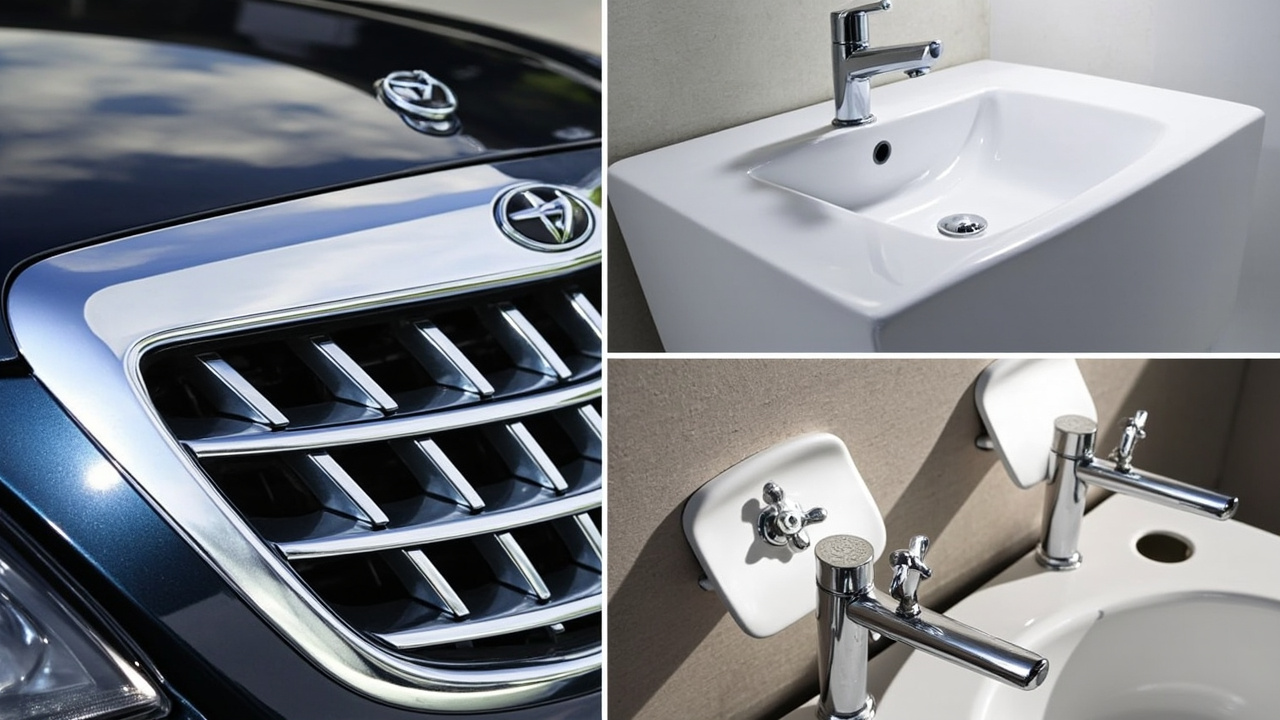
Plastic electroplating (also called plastic metallization or plastic plating in the industry) is a process that turns plastic parts into "surface-is-real-metal" components: first, electroless plating is used to seed a conductive metal layer on the plastic surface, then electroplating builds up copper, nickel, and chromium layer by layer, ultimately achieving a mirror-like chrome feel identical to metal electroplating, while the substrate remains lightweight plastic. It combines the molding freedom of plastic with the appearance/conductivity of metal, and is widely used in automotive grille trims, sanitary ware, appliance knobs, cosmetic caps, and 3C decorative parts. However, the difficulty of plastic electroplating does not lie in the "plating", but in the "pre-plating plastic treatment" and "post-plating protection"—these two stages are the key to yield and environmental compliance. This article thoroughly explains the pretreatment, electroplating, and post-protection coatings of plastic electroplating, and together sorts out the accompanying coating systems (pretreatment primer, conductive paint, post-plating clear coat), helping coating and electroplating engineers build a complete chain understanding.
Kexin New Materials (Guangdong) Co., Ltd. has engineering experience in supporting coatings related to plastic metallization (pretreatment primer, post-protection topcoat, and electroplating alternative routes), and a firsthand understanding of the adhesion and environmental pain points in plastic plating projects. Its Foshan base has long served automotive trim, sanitary ware, and home appliance customers in South China, accumulating implementable cases in PP primer, water-based metal coating, and chrome-like systems.
I. Why Plastic Can Be Electroplated
Ordinary plastic is non-conductive and surface-inert, and cannot be electroplated. The trick of plastic electroplating is "electroless plating first, then electroplating": through pretreatment, micro-roughness and catalytic centers are created on the plastic surface, allowing electroless nickel/electroless copper to autocatalytically deposit a conductive metal film (about 0.2–1 micron) at room temperature. This film makes the plastic "become a conductor", enabling subsequent electrified copper-nickel-chrome plating to build up thickness. ABS is the most classic plastic electroplating substrate, because its butadiene phase is easily roughened to form micropores, favoring anchoring; PC, PA, PP, etc. require modification or more complex treatment. From a physical essence, electroless plating uses a reducing agent (such as sodium hypophosphite, formaldehyde, dimethylamine borane) to reduce metal ions in solution into metal, depositing on the catalytically activated surface—this is a thermodynamically spontaneous process kinetically regulated by surface catalysis. Without the palladium catalytic nuclei created by pretreatment, the electroless plating solution simply will not initiate on the plastic surface, which is the root of pretreatment's "vital" status. From reaction thermodynamics, electroless plating is a reduction process regulated by surface catalysis: taking electroless nickel as an example, sodium hypophosphite is oxidized on the palladium-catalyzed surface to release electrons, reducing Ni²⁺ in solution to metallic nickel and codepositing phosphorus, forming an amorphous Ni-P alloy; the autocatalytic nature of the reducing agent allows deposition to continue rather than being limited to the initial spots. Understanding this is important—if pretreatment fails to arrange palladium nuclei of sufficient density and stable activity on the plastic surface, electroless plating will suffer "slow start, many skipped plates", and no matter how good the subsequent electroplating is, it cannot be saved. This is also why the process control focus of plastic plating always rests on pretreatment and interface, not the plating bath itself.
II. Full View of Plastic Plating Substrates: Physical and Chemical Differences Between ABS and PP
To understand why pre- and post-treatment coatings are necessary, one must first look at the substrate. ABS (acrylonitrile-butadiene-styrene terpolymer) contains dispersed butadiene rubber phase internally; during chromic acid roughening, the butadiene phase is relatively easily oxidized and dissolved out, leaving micron-scale pits and microcracks that provide mechanical anchors for the subsequent coating; meanwhile, ABS has moderate surface energy and controllable chemical resistance within the roughening window, hence it is called "plastic tailor-made for electroplating". In contrast, PP (polypropylene) is a semi-crystalline polyolefin with extremely low surface energy (about 29–31 mN/m), strong chemical inertness, and no easily oxidized rubber phase, so conventional chromic acid roughening is almost ineffective—this is why PP for plastic plating must rely on adhesion-promoting primer or modified material. PC (polycarbonate) has rigid molecules and is prone to stress cracking, requiring careful temperature control during roughening; PA (nylon) is hygroscopic and contains amide bonds, so pretreatment must balance dehydration and activation; PBT/PET have good heat resistance but high crystallinity, with a narrow roughening window. The chemical composition of the substrate directly determines the pretreatment strategy and whether coating intervention is needed. Quantifying surface energy is illustrative: ABS is about 38–42 mN/m, within the wettable range of most coatings; PP is only 29–31 mN/m, below the critical surface tension of common coatings, causing film shrinkage and adhesion failure; PC is about 40–45 mN/m but with rigid molecules and high internal stress. Therefore, at the material selection stage, "metalizability" must be included in the review: not only mechanical properties and cost, but also roughening window, stress level, and whether coating bridging is needed. When serving customers in Foshan, Kexin New Materials often lists substrate confirmation as the first step of sampling, avoiding repeated trial-and-error on wrong substrates later.
III. Full Process of the Six-Step Pretreatment Method
Plastic electroplating pretreatment is the vital point of yield. The typical process is: degreasing → roughening (chromic acid etches ABS surface, dissolving butadiene phase to form micropore anchors) → neutralization/reduction (remove residual chromium, environmental key) → activation (adsorb palladium catalyst) → acceleration (expose palladium nuclei) → electroless nickel/copper (autocatalytic deposition of conductive layer). If any step loses control, the subsequent coating will peel off in sheets. The degreasing stage commonly uses alkaline degreasers or solvent wiping to remove mold release agents and oil stains; the roughening stage is the core, treated by a chromic acid-sulfuric acid system at 60–70 ℃ for several minutes; the neutralization stage uses sodium bisulfite or hydrochloric acid to reduce residual hexavalent chromium to trivalent and wash it off; the activation stage immerses in palladium colloid (e.g., palladium chloride-tin salt colloid) to adsorb palladium particles onto the roughened micropores; the acceleration stage uses dilute acid to dissolve the tin shell and expose active palladium nuclei; finally, electroless nickel autocatalytically deposits a 0.2–0.6 µm conductive layer under palladium catalysis. In this six-step chain, temperature, concentration, time, and water quality (especially the activation stage is extremely sensitive to metal impurities) must all be closed-loop controlled. The six steps are not independent but a strongly coupled causal chain: incomplete degreasing isolates the roughening solution with oil and causes local roughening failure; insufficient roughening makes activation adsorption sites sparse; incomplete neutralization leaves residual hexavalent chromium that poisons the activation colloid; poor activation directly causes electroless plating skip; over-acceleration dissolves the palladium nuclei together. Each step depends on the qualified output of the previous step, so modern production lines have extremely high water quality requirements—activation and electroless plating stages mostly use pure water (conductivity < tens of µS/cm) to prevent impurities like Ca²⁺, Fe³⁺ from causing burning or skipping. Operationally, drag-out (solution carryover) must be controlled to save chemicals and reduce wastewater.
IV. Roughening Mechanism: Chromic Acid Etching and Micropore Anchoring
Roughening is not simply "making the surface rough", but a selective chemical etching. The chromic acid-sulfuric acid mixture preferentially attacks the butadiene phase in ABS (unsaturated double bonds are easily oxidized), dissolving the rubber phase in the form of spherical pits, forming a honeycomb-like micropore of 0.1–several microns in diameter; the styrene-acrylonitrile continuous phase is relatively corrosion-resistant and retained as the "network skeleton" between micropores. This micro-morphology simultaneously provides (1) huge specific surface area to increase van der Waals and mechanical interlocking, (2) stress release channels to reduce coating internal stress cracking. Insufficient roughening means few anchors and poor adhesion; excessive roughening causes plastic stress cracking, surface embrittlement, and even "over-etched pitted surface". The degree of roughening is quantitatively judged by weight loss rate, surface contact angle, and SEM morphology. The hexavalent chromium in the roughening solution is an environmental pain point; the industry is shifting to chromium-free roughening (e.g., permanganic acid, plasma, laser roughening) and shorter processes. Observing the roughened surface by SEM, the typical morphology is dense spherical pores interwoven with microcracks; pore size distribution and depth are directly related to adhesion: too shallow pores mean weak anchoring, too deep pores mean stress concentration and easy cracking. The industry often uses "roughness Ra and pore density" as process monitoring indicators of roughening degree, but more reliable is destructive adhesion back-inference. Contact angle testing can also indirectly reflect whether roughening is sufficient—after roughening, surface polarity rises and water contact angle drops significantly. It is worth mentioning that roughening also introduces oxygen-containing functional groups (carbonyl, carboxyl) on the surface; these polar groups help the adsorption of subsequent activation solution and coating bonding, a chemical benefit hardly replaceable by mere physical sanding.
V. Chromium-Free Roughening Alternative Routes
The carcinogenicity and high toxicity of hexavalent chromium make chromium-free roughening a global transformation direction for plastic electroplating lines. There are three main alternatives: (1) permanganate system (e.g., potassium permanganate-phosphoric acid), which relies on strong oxidation to create pores on ABS surface, but pore morphology and adhesion window differ from chromic acid, requiring parameter re-tuning; (2) plasma/ozone roughening, using high-energy particle bombardment or surface oxidation to increase polarity and micro-roughness, with almost no waste liquid, but high equipment investment and great uniformity challenges for complex parts; (3) laser/UV roughening, precisely creating local anchors, suitable for selective metallization (e.g., only plating the logo area). In addition, there is a "physical roughening + primer" composite route: first sandblasting or flame treatment to increase surface energy, then spray adhesion-promoting primer, bypassing chemical roughening. The water-based metal and chrome-like systems promoted by Kexin New Materials at its Foshan base are exactly one of the green alternative options for plastic electroplating, with the idea of reducing roughening dependence and using coatings to bridge plastic and metal.
VI. Activation and Catalysis: Palladium Colloid and Sensitization
The activation stage determines whether electroless plating can initiate uniformly. The traditional "two-step method" first uses stannous chloride sensitization (adsorbing Sn²⁺ on the surface), then palladium chloride activation (Sn²⁺ reduces Pd²⁺ to metallic palladium nuclei); the modern "one-step colloid method" directly uses palladium-tin colloid (e.g., PdCl₂-SnCl₂-HCl colloid), which adsorbs on the roughened surface, then undergoes acceleration (dilute hydrochloric acid or fluoride) to dissolve the outer tin shell and expose active palladium nuclei. The density of palladium nuclei directly determines the electroless plating initiation rate—too sparse nuclei mean slow start and skip; too dense means high palladium consumption and rising cost. The activation solution is extremely sensitive to metal impurities such as Fe³⁺, Cu²⁺, which poison the colloid and cause skipping, so the activation bath needs online pure water and regular replacement. For substrates like PP without roughening anchors, activation often needs to combine with catalytic particles or conductive fillers in the primer to be meaningful.
VII. Electroless Nickel and Electroless Copper
The electroless plating layer is the critical 0.2–1 µm thin film that "turns plastic into a conductor". Electroless nickel (reduced by sodium hypophosphite, yielding Ni-P alloy) has high hardness, corrosion resistance, and good bonding, and is the mainstream conductive underlayer for plastic electroplating; electroless copper (reduced by formaldehyde, pure copper) has better conductivity and ductility, suitable for subsequent thick copper electroplating, but formaldehyde (carcinogenic) and formaldehyde waste gas are strictly controlled, and it requires higher pretreatment cleanliness. In thickness control, 0.2 µm is enough to satisfy conductive initiation, but to reduce skipping and improve thermal shock resistance, it is often made 0.4–0.8 µm. The electroless plating solution needs controlled pH, temperature, load, and stabilizer (to prevent self-decomposition burning), and regular filtration to remove particles. The crystalline density of the electroless layer directly affects the flatness and bonding of the subsequent electroplating layer, and is a mandatory QC inspection item. The Ni-P alloy from electroless nickel shows a transition from crystalline to amorphous with different phosphorus content (usually 3–12 %); high-phosphorus layer has better corrosion resistance but slightly lower hardness, low-phosphorus layer has better solderability, and the formula is chosen by use. Although electroless copper has better conductivity and ductility, the toxicity and volatility of formaldehyde make it stricter in working environment and waste gas control; some production regions have restricted its use, and formaldehyde-free systems are still under development. Regardless of nickel or copper, the electroless solution needs stabilizers (e.g., trace lead, thiourea) to suppress homogeneous decomposition, and continuous filtration to remove catalytic particles, otherwise it will "self-burn" and clog the bath and racks.
VIII. Electroplating Layer Structure: Copper/Nickel/Chromium
On top of the electroless conductive layer, the following electroplating is applied in sequence: copper sulfate (to thicken conductivity and level the surface) → bright nickel (corrosion resistance, decoration, main thickness contributor) → chromium plating or chrome substitute (outermost layer, mirror finish and wear resistance). A typical total coating thickness is tens of microns. The nickel layer is the main anti-corrosion component, while the chromium layer is thin and hard, providing mirror finish and weather resistance. Interlayer adhesion must be good, otherwise peeling occurs. The approximate thickness distribution is: pyrophosphate copper 5–15 µm as base and leveling, semi-bright nickel + bright nickel 10–25 µm for anti-corrosion and decoration, microporous/microcracked chromium 0.1–0.5 µm for hard surface and mirror finish. The nickel layer often uses a "double-layer nickel + microporous chromium" combination to interrupt corrosion paths; for high corrosion-resistance requirements (such as automotive exterior trim), the nickel is thickened and microporous chromium is used to disperse corrosion current. The potential difference design between layers is the core of anti-corrosion; abuse of single-layer bright nickel easily causes "linear corrosion" at scratches. The essence of anti-corrosion design lies in interlayer potential and microporous structure: once single-layer bright nickel is scratched, corrosion advances straight from the scratch toward the substrate; whereas the "semi-bright nickel (more negative potential) + bright nickel (more positive potential) + microporous chromium" combination disperses the corrosion current uniformly through micropores, so corrosion occurs by uniform thinning rather than linear perforation, multiplying the service life. Microporous chromium is achieved by introducing extremely fine inert particles (such as barium sulfate, diatomite) on the nickel layer or by secondary nickel plating to create pores. For high-salt-spray scenarios such as automotive exterior trim, the total nickel thickness is also increased and it evolves toward "double-layer nickel + microcracked chromium". These details determine that plating layers that "look equally shiny" may differ in warranty life by several times.IX. ABS Plastic Plating Process Window and Parameters
Taking ABS as an example, the typical plastic plating parameter window is: etching 60–70 ℃, CrO₃ 300–450 g/L, H₂SO₄ 200–350 g/L, time 3–10 min (depending on part thickness and requirements); neutralization 30–50 ℃, sodium bisulfite 30–80 g/L; activation 20–40 ℃, colloidal palladium 50–200 ppm Pd; acceleration 1–3 % HCl or fluoride; electroless nickel 30–45 ℃, pH 4.5–5.0, thickness 0.4–0.8 µm; electroplating pyrophosphate copper 20–30 ℃, nickel 50–60 ℃, chromium 40–50 ℃. These parameters are not isolated; over-etching compresses the fault tolerance of subsequent activation and electroless plating, and the entire line must be adjusted in linkage. ABS has a wide etching window (±20% still acceptable), which is the fundamental reason it became a classic substrate; switching substrates means reopening the window.
X. The Difficulty of PP: Extremely Low Surface Energy and the Necessity of Primer
The biggest obstacle to plastic plating on PP is its extremely low surface energy and dense crystallinity; chromic acid etching is almost ineffective, microporous anchoring fails, and electroless plating directly misses plates. There are three types of solutions: (1) flame/corona/plasma treatment to raise surface energy above 40 mN/m, but the effect decays over time and is uneven on complex parts; (2) use modified PP (such as maleic anhydride-grafted PP, PP/elastomer blend) to introduce polar phases that can be etched or improve adhesion; (3) the most practical is to spray an adhesion-promoting primer (typically chlorinated polyolefin CPO system), forming a strongly adhesive transition layer on PP, then applying conductive paint or direct plating on it. For mass-produced PP sanitary ware and home appliance parts, the primer route has become the de facto standard. Kexin New Materials has launched a dedicated adhesion primer for PP at its Foshan base, achieving stable plastic plating yield with customer injection-molded parts. Flame treatment uses a high-temperature oxidizing flame to introduce polar oxygen-containing groups on the PP surface; it is low-cost but difficult to control uniformity and aging (decays from several hours to days after treatment); corona/plasma is more uniform and can be inline, but the equipment is expensive and shielding of deep-cavity parts is difficult. Therefore, mass PP plastic plating more commonly uses the "modified PP + CPO primer" double insurance: modification solves attachability, and primer solves strong bonding and plating compatibility. For cases where material cannot be changed (e.g., customer-specified raw material), CPO primer is almost the only robust way out, which also explains why yield improvement in PP plastic plating often comes not from changing electroplating but from changing coating.
XI. Chlorinated Polyolefin (CPO) Adhesion-Promoting Primer
Chlorinated Polyolefin (CPO) is a classic material for solving PP adhesion. Its molecular chain has a similar structure to PP, and can swell and diffuse into the PP surface to form "interpenetrating" anchoring, while the side-chain chlorine provides polarity, bridging the upper coating or electroless/electroplating layer. CPO primer is usually applied as a thin spray of 3–8 µm, baked at 60–80 ℃ for 10–20 min to promote interfacial diffusion with PP. Key indicators are chlorination degree (typically 20–40 %), molecular weight (affecting film formation and adhesion balance) and solvent system (must swell PP without causing cracking). CPO can also be used as a base for direct topcoat on home appliance PP parts, not limited to plastic plating. For the plastic plating route, a conductive paint is often sprayed or special activation is done on top of the CPO primer before plating; for direct electroless plating, the primer must contain catalytic activity or be paired with activation. The difficulty in formulation is: too low chlorination gives poor adhesion, too high makes it brittle, yellowing and poor weather resistance. In application, CPO primer is mostly applied by air or electrostatic spraying, with a film thickness of 3–8 µm; too thick weakens cohesion and easily cracks; the baking window must allow the resin to swell and diffuse into PP, but not overheat to deform PP. Fluctuations in the PP grade of incoming material significantly affect primer effect, so mass production must lock raw material and batch, and periodically do cross-cut + boiling water verification. For PP parts requiring conductive paint, the CPO primer must also be compatible with the upper conductive paint resin to avoid weak interlayer interface.
XII. Conductive Primer/Conductive Paint Route (Bypassing Etching)
For difficult-to-etch plastics (PP, PE, some engineering plastics, even ceramics/glass), the industry commonly uses the "conductive paint" route to bypass etching: first spray a conductive coating containing metal fillers (silver powder, copper powder, graphite, nickel powder or stainless steel fiber) on the part to form a 1–10 µm conductive layer with surface resistance <1–10 Ω/□, then directly enter the plating bath to thicken copper-nickel-chromium. This route replaces "chemical etching for anchoring" with "conductive coating + physical adhesion", eliminating hexavalent chromium etching, with obvious environmental advantages, but requires extremely high adhesion of the conductive paint itself (still relying on primer or surface treatment) and conductive uniformity. The resin system of conductive paint must be compatible with plating solution (acid, alkali, temperature resistant), commonly modified acrylic, epoxy or polyurethane. The coating adhesion of the conductive paint route relies more on mechanical/chemical bonding between coating and substrate rather than microporous anchoring, so substrate pretreatment (degreasing, primer) is even more critical. Another advantage of the conductive paint route is "selective metallization": use mask or screen printing to spray conductive paint only on the area to be plated; unsprayed areas are non-conductive and not plated, eliminating whole-part insulation and stripping. This is extremely useful for logos, decorative strips, and local shielding. But this route has strict requirements on application consistency of conductive paint—film thickness fluctuation directly causes uneven resistance and unbalanced current distribution, leading to "thickness mottling" or even local burning of the coating. Therefore, the spraying section is often equipped with online film thickness measurement and resistance sampling, and the rack design must ensure good electrical contact between the conductive paint layer and the plating cathode, otherwise the plating current cannot be transmitted.
XIII. Conductive Paint Formulation: Silver/Copper/Graphite Systems
The performance of conductive paint is determined by three components: conductive filler, resin and solvent. Silver powder has the best conductivity, good oxidation resistance and low contact resistance, but high cost, mostly used for high-reliability electronic shielding and high-end trim; copper powder is low-cost and conductive, but easily oxidizes and needs anti-oxidation coating (such as silver-coated copper powder), otherwise plating solution erosion causes resistance to surge and coating to become mottled; graphite/carbon black is low-cost and corrosion-resistant, but weak conductivity and requires larger film thickness; nickel powder and stainless steel fiber compromise between corrosion resistance and cost. Filler morphology (flake better than spherical, easier to form conductive path), volume fraction (typically 30–60 wt%), dispersion (prevent agglomeration) and resin wetting of filler jointly determine final resistivity and adhesion. The formulation must also balance applicability (viscosity, leveling, flash dry) and plating compatibility. Kexin New Materials has formulation reserves for such conductive primers, and can customize filler and resin matching for different PP/ABS substrates. Worth mentioning separately is "silver-coated copper powder": copper as core, thin silver outside, balancing copper's low cost and silver's oxidation resistance, an optimal choice for performance and cost, but coating integrity determines its resistance to plating solution erosion; poor coating oxidizes and darkens before plating. Filler particle size distribution also matters—coarse-fine combination can form a denser conductive path at lower filler content, reducing cost while maintaining conductivity. The resin end must balance wetting of filler, adhesion to substrate (after primer), and resistance to plating solution (acid/alkali/oxidation) without swelling or falling off. Kexin New Materials' formulation experience in conductive primer revolves around the "filler-resin-substrate" matching.
XIV. Post-Plating Protective Topcoat: Transparent Clear Coat
Plastic plating is not "done after plating". The post-plating section often has a "protective topcoat": some parts, to improve weather resistance, anti-fingerprint or tinting, spray a layer of transparent protective paint (similar to PVD topcoat) on the chromium layer. The plating layer (especially bright chromium) is hard but thin; long-term outdoor exposure causes loss of gloss, pitting, and easily leaves fingerprints; transparent clear coat provides additional weather resistance, chemical resistance and scratch barrier. Clear coats are divided into solvent-based (two-component polyurethane, acrylic) and water-based/UV curing types. Application requires extremely thin and transparent (typically 5–15 µm), must not cover the metal mirror, must not yellow, must not reduce adhesion. For sanitary ware and automotive exterior parts, clear coating is a key process to extend warranty. Post-plating clear coat, like pre-plating primer, is the "interface between coating enterprises and plating factories". Solvent-based two-component polyurethane clear coat has mature comprehensive performance, balanced adhesion and weather resistance, and remains mainstream; acrylic clear coat is hard and brittle, good scratch resistance but slightly poor toughness; UV-curable clear coat is solvent-free, seconds-level curing, high line speed, but parts must be flat to receive light, and curing energy must be sufficient for dark metal surfaces; water-based clear coat has low VOC but film formation is sensitive to temperature and humidity, and initial water resistance needs curing. Regardless of type, application requires "thin, even, clean": film thickness over 15–20 µm easily cracks and sags, covering metallic feel; insufficient thickness gives inadequate protection. Before spraying, chromium surface must be degreased and fingerprint-free and lightly treated to enhance wetting, otherwise clear coat will locally crater or peel entirely.
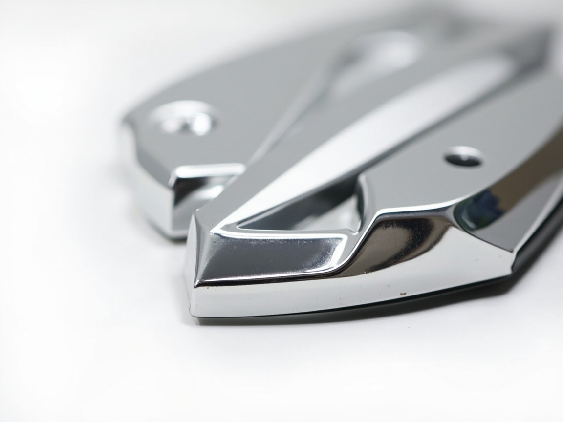
XV. Weather Resistance and Anti-Fingerprint of Clear Coat
The core performance of clear coat is weather resistance (QUV/xenon lamp aging without yellowing, cracking) and anti-fingerprint (low surface energy, easy cleaning). Outdoor parts need to pass 1000–2000 h xenon lamp aging and CASS composite verification; anti-fingerprint often reduces surface energy by adding fluorine or siloxane additives, but excess sacrifices interlayer adhesion. UV-curable clear coat, being solvent-free, fast curing and high hardness, is gradually replacing some solvent-based types; water-based clear coat fits VOC reduction. Interlayer bonding between clear coat and chromium layer relies on chromium surface micro-roughness and cleaning (release agent residue is an adhesion killer), often requiring light post-chromium treatment (such as dilute acid activation or plasma) before spraying. Kexin New Materials has engineering solutions for water-based clear coat and anti-fingerprint systems, which can connect with post-plastic-plating treatment processes. Anti-fingerprint grade can be quantified by visual fingerprint residue + contact angle; lower surface energy leaves less trace, but too low (<20 mN/m) weakens clear coat adhesion to chromium surface, requiring trade-off in additive dosage. For weather resistance, QUV 340 nm cycle 1000 h is often the boundary between indoor and outdoor; outdoor parts should further undergo xenon full-spectrum aging. If clear coat contains UV absorber and hindered amine light stabilizer (HALS), it can significantly delay the matting of nickel under chromium layer and extend warranty.
XVI. Local Insulation and Edge Protection Coating
Plated plastic electrical parts often have internal cavities, snaps, threads, and assembly surfaces that cannot be plated (otherwise liquid retention, corrosion, and assembly interference would occur). In the process, "insulating ink/paint" is used for selective masking of these areas: either plate the whole part first and then seal the cavities and snaps with a peelable or permanent insulating coating, or spot-apply plating-resistant paint to non-plated areas before plating. The insulating coating must resist plating solutions (acid, alkali, oxidation), be easy to apply, easy to remove (peelable type) or permanently bonded (structural type). At edges and sharp corners, the plating is often thin, with stress concentration and easy exposure of the plastic substrate; therefore, at the injection molding design stage, corners are rounded, wall thickness is increased, and local touch-up coating is applied for protection. This "coating step" may seem marginal, but it is critical to the yield and assembly reliability of plated plastic parts, and is also where coating knowledge comes into play. Peelable insulating paint is mostly rubber or thermoplastic systems, which can be torn off after plating, suitable for small batches and multiple varieties; permanent insulating coating is epoxy or modified acrylic, which remains with the part after curing, used for structural sealing. Masking precision determines the aesthetics of the plating boundary and assembly, often coordinated with CNC dispensing or screen printing to achieve fine line-width masking. For parts with threads, high-temperature resistant rubber plugs are commonly used for physical masking to avoid paint film entering the threads and affecting screwing.
17. Process Flow Diagram and Takt Time
A complete plated plastic line is usually laid out as: loading → degreasing → water rinse → etching → recovery → water rinse → neutralization → water rinse → activation → water rinse → accelerator removal → water rinse → electroless nickel (or copper) → water rinse → copper plating → water rinse → nickel plating → water rinse → chrome plating → water rinse → drying → unloading → (post-treatment) clear coat/insulation. Takt time is determined by line speed and tank time; rack design (conductivity, flow shielding, anti-liquid-pocketing) directly determines uniformity and scrap rate. For the conductive paint route, after degreasing/primer, insert "spray conductive paint → curing" before plating. The whole line mostly uses automatic overhead crane or carousel line, with parameters under closed-loop control by central PLC and online analysis (concentration, temperature, pH). Too long takt time increases liquid pocket carry-out, chemical consumption and wastewater; too short takt time leads to insufficient etching/activation. Process design must balance the two. Takt setting is usually based on the "slowest step", e.g., 6 min etching determines main line speed, other tanks arranged by dwell time; rack density affects loading and uniformity, too dense causes poor convection in tank and uneven thickness. Modern carousel lines optimize rack spacing and swing amplitude via simulation, controlling thickness CV within 10%. When changing type, use dummy parts to run and calibrate the line first, then load good parts to reduce first-batch scrap.
18. Key Process Parameters: Temperature, Thickness, Curing
Parameters of the whole plated plastic chain can be summarized into three types: temperature (etching 60–70 ℃, activation room temp, electroless nickel 30–45 ℃, nickel plating 50–60 ℃, chrome plating 40–50 ℃), thickness (electroless 0.4–0.8 µm, pyrophosphate copper 5–15 µm, nickel 10–25 µm, chrome 0.1–0.5 µm, clear coat 5–15 µm), curing (CPO primer 60–80 ℃/10–20 min, conductive paint 80–120 ℃/15–30 min, two-component clear coat room temp or 60–80 ℃ cure, UV clear coat seconds). These numbers are not fixed, they vary with substrate, part shape, equipment and requirements. Temperature drift of 2–3 ℃ can cause over-etching or activation failure; insufficient thickness directly sacrifices corrosion resistance; insufficient curing leads to poor coating adhesion and chemical resistance. The production line must be equipped with high-precision temperature control, online/offline thickness measurement (XRF, metallographic cross-section) and cure degree detection (DMA/solvent wipe). Thickness measurement recommends XRF for copper-nickel-chrome online sampling, metallographic cross-section for destructive full-layer analysis, cross-validated; cure degree of clear coat can be indirectly judged by MEK wipe count or pencil hardness. The first signal of parameter drift is often appearance (haze, mottling, pinholes), so operators need to keep color samples and specular gloss (e.g., 60° glossmeter) every shift. Writing key parameters into SPC control charts can detect trend deviations early.
19. Line and Equipment: Racks/Plating Tanks/Spraying
Plated plastic equipment requires heavy investment and detailed maintenance. Plating tanks are mostly PP/PVC lined, titanium heating tubes, PP in-tank spray and overflow; racks are titanium or rubber-coated steel, needing both conductivity and anti-liquid-pocketing, anti-plating on non-plated areas; automatic lines equipped with overhead crane, carousel conveyor and swing mechanism for uniformity. Spraying section (primer, conductive paint, clear coat) uses reciprocator or robot, with electrostatic spraying to improve transfer efficiency and film uniformity; spray booth needs constant temp/humidity and solvent concentration monitoring. Wastewater treatment (hexavalent chromium reduction, complexed nickel breaking, acid-alkali neutralization) is a hard compliance cost. Kexin New Materials' supporting coatings at Foshan base are mostly implemented in "offline spraying + customer plating" collaboration mode; its pretreatment primer and clear coat can be done on ordinary spray line, lowering customer's line modification threshold. Rack design is often underestimated but extremely critical: it simultaneously undertakes four roles of conduction, support, flow shielding and anti-liquid-pocketing. Insufficient conductive cross-section limits current causing thin plating; poor flow shielding plates the back side too, increasing consumption and looking bad; liquid pocketing carries chemical to next tank causing cross-contamination and more wastewater. High-end lines use titanium rubber-coated racks, rubber-coated on non-plated areas, bare titanium on plated areas, with profiled supports to reduce pocketing. Electrostatic spraying in spray section can raise coating utilization from 30–40% of air spray to 60–80%, significantly reducing coating and VOC cost. Wastewater section is compliance key: hexavalent chromium reduced to trivalent then precipitated, complexed nickel must be broken before coagulation removal, failing treatment directly limits production.
20. PP Modified Material and Primer-free Progress
To reduce PP plated plastic's dependence on primer, material side is advancing modified PP: grafting polar monomers (e.g., PP-g-MAH) to introduce attachable polar sites; PP/elastomer (EPDM) blend to create etchable phase; filling mineral or glass fiber to improve dimensional stability and plating support. Some modified PP can already obtain acceptable anchoring under mild etching, achieving "weight reduction + platable". In addition, primer-free conductive paint (with strong adhesive resin) and low-temperature plasma direct activation are also compressing the primer process. But modification sacrifices some of PP's low-cost and lightweight advantages; material selection is a re-balance of "cost-performance-process". For large sanitary ware parts, the robust route of CPO primer + conductive paint is still mainly used. After PP-g-MAH polar site improvement, certain anchoring can be obtained under mild conditions, but still hard to reach ABS etching strength, most still with primer; glass fiber reinforced PP needs attention to plating pinholes at fiber tips. Primer-free conductive paint introduces strong adhesive resin (e.g., modified vinyl chloride-vinyl acetate, epoxy) to directly bite PP, saving one process but hard to balance conductivity and adhesion, suitable for medium-low requirement decorative shielding parts. Synergistic selection of material and coating is the key lever for PP plated plastic cost reduction.
21. Quality Control: Adhesion Test
Adhesion of plated plastic is a life-or-death line. Standard methods include: thermal shock (cold-hot impact) to see blistering/peeling; cross-cut/peel (e.g., tape or tensile rivet) for quantitative adhesion; bend/impact for toughness; cross-cut + tape (for clear coat). Adhesion target of plating to plastic usually requires passing 100 ℃ boiling water/hot oil or -40–85 ℃ thermal cycle without detachment. Test must sample at representative parts and weak areas like edges, inner concaves, not only flat surfaces. Kexin New Materials, when delivering supporting coatings, agrees adhesion acceptance threshold with customer (e.g., cross-cut class 0, thermal shock no detachment), and replicates customer's post-plating state for verification, avoiding the dispute of "coating qualified but plating detached". Pull-off method (e.g., bond aluminum stud then tensile test for adhesion strength, MPa) is more quantitative than cross-cut, suitable for R&D benchmarking; passing thermal shock but failing room-temp cross-cut often points to weak interfacial bonding rather than thermal stress. Sampling must cover low-current/low-adhesion areas like sag ends, inner corners, thread roots, where failure occurs first. Kexin New Materials suggests including adhesion in both incoming and per-batch outgoing confirmation, not only final inspection.
22. Thermal Shock Test (Cold-Hot Impact)
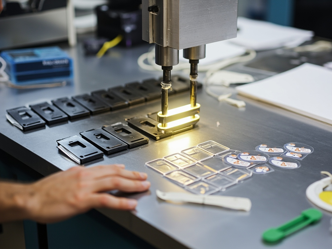
Thermal shock is the most severe and common reliability threshold for plated plastic. Plastic and metal have large thermal expansion coefficient difference (plastic about 50–100 ppm/℃, metal about 10–20 ppm/℃), sudden temperature change accumulates shear stress at interface, insufficient adhesion causes blistering, peeling. Typical conditions: -40 ℃ 30 min ↔ 85 ℃ 30 min cycle 5–10 times, or 100 ℃ boiling water ↔ 0 ℃ ice water. Judgment standard: no blistering, no peeling, no cracking. Thermal shock failure often exposes pretreatment (insufficient etching, poor activation) or primer (weak CPO adhesion, insufficient curing) issues, is the first handle for troubleshooting. For automotive exterior parts, thermal shock is often serially combined with salt spray, UV aging into "combined environmental test". Thermal shock severity must match use environment: indoor parts can use -30–80 ℃ milder cycle, automotive parts often require -40–90 ℃ with humidity variation; besides "no detachment", also check haze, discoloration. To expose hidden risks, some automakers use "thermal shock + salt spray" serial instead of separate, closer to real aging. Test coupons and real parts have different stress states, important parts must use real parts for confirmation.
23. CASS and Neutral Salt Spray
Corrosion resistance verified by salt spray. Neutral Salt Spray (NSS) uses 5% NaCl, 35 ℃ continuous spray, to see red rust/blister time; CASS (Copper-accelerated Acetic Acid Salt Spray) adds CuCl₂ and acetic acid, 50 ℃, stronger acceleration, is mainstream threshold for automotive coatings (e.g., 16–96 h varies). Plated plastic salt spray failure often shows: insufficient nickel causing substrate corrosion, "pitting expanding to sheet" at micro-pores of chrome, priority corrosion at edge plastic exposure. Improvement: thicken nickel, use micro-porous chrome to disperse corrosion, post-plate clear coat sealing, and ensure complete coating without pinholes. Sanitary ware parts in long-term humid hot chlorinated environment often require higher than ordinary decorative parts. Salt spray samples also need edge and assembly surface sampling, flat passing not equal to whole part qualified. CASS rating per ISO 10289 or customer spec calculates protection grade (higher better), and counts blister, red rust area; micro-porous chrome corrosion shows uniform pitting rather than large red rust, better rating. To distinguish "insufficient plating" from "clear coat leak", do "with clear coat / without clear coat" comparison salt spray to locate failure link. Sanitary ware parts often add "warm water cycle (e.g., 70 ℃ hot water ↔ cold water)" to simulate use.
24. Common Defects and Troubleshooting
| Defect | Cause | Countermeasure |
|---|---|---|
| Plating peeling | Insufficient etching / poor activation / weak primer | Adjust etching, check activation solution, strengthen CPO primer |
| Surface pitting | Over-etching / substrate defect / gas | Control etching, change material, improve agitation |
| Missed plating | Uneven conductive layer / insufficient activation | Check electroless, supplement conductive paint, re-activate |
| Stress cracking | Strong etching / substrate stress | Annealing, reduce etching, change substrate |
| Blistering (thermal shock) | Weak interfacial adhesion / liquid pocketing | Strengthen primer, remove pocketing, reduce interfacial stress |
| Poor corrosion resistance | Thin nickel / missing chrome / pinhole | Increase nickel thickness, ensure chrome complete, add clear coat |
| Plating mottling | Conductive paint oxidation / uneven current | Use anti-oxidation filler, adjust rack |
| eco-standard not met | hexavalent chromium roughening / three wastes | switch to chromium-free roughening, add wastewater treatment |
| clear coat delamination | chromium surface dirty / wrong clear coat selected | clean chromium surface, replace with compatible clear coat |
Defect localization should be traced backward segment by segment from "pretreatment → plating → coating"; examining the plating layer alone often leads to misdiagnosis.
25. Automotive Industry Applications: Grille / Emblem / Trim
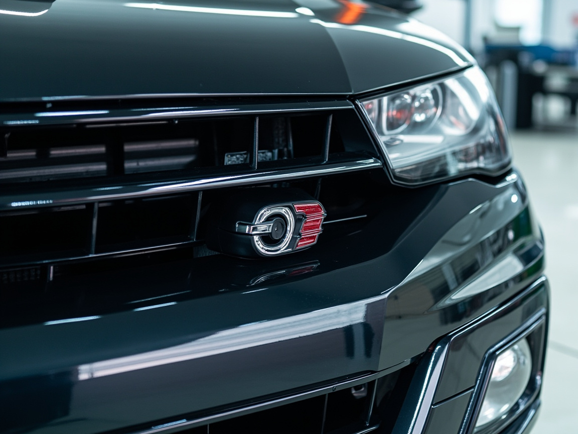
Automotive is the largest high-value market for plastic electroplating. Grilles, front and rear emblems, window frame trims, door handles, and shift panels extensively use ABS/ABS-PC plastic electroplating bright chrome, which is both lightweight and offers a metallic luxury feel. Requirements are extremely strict: thermal shock, CASS, UV aging, stone impact, and detergent resistance must all be passed, and batch color difference and mirror consistency are difficult to control. As a trend, large-size grilles are gradually shifting to PVD or spray imitation chrome to reduce the hexavalent chromium burden, but small emblems and high-precision trims still prefer the real-metal thick-plating feel of plastic electroplating. PP substrate bumper accessories mostly adopt primer + conductive paint or PVD. Kexin New Materials serves South China automotive trim factories; a common practice is for the electroplating plant to complete plating, and the coating plant provides CPO primer and post clear coat in coordination. OEMs have instrumental thresholds for color difference and image clarity (DOI) of bright chrome parts; large-area plating on grilles especially tests thickness uniformity and rack design. To reduce hexavalent chromium, front bumper accessories mostly switch to PVD or imitation chrome, while only the grille emblem retains plastic electroplating to preserve the "thick metal feel". Kexin New Materials often participates in such projects with a "primer + clear coat" dual-coating approach, ensuring the plated layer delivered by the electroplating plant already has anti-fingerprint and weather-resistant protection before assembly.
26. Bathroom and Hardware Applications
Bathroom is the second largest market for plastic electroplating: faucet housings, shower panels, towel rings, and soap dishes use ABS or modified PP plastic electroplating to imitate stainless steel/chrome, replacing some metal to reduce weight and cost. The bathroom environment is hot and humid, with chlorine-containing cleaners and hard water, so corrosion resistance and clear coat requirements are higher than ordinary decorative parts, often requiring thickened nickel + clear coat dual protection. PP parts appear in large numbers here, relying on CPO primer and conductive paint routes. Hardware small parts (hinge covers, handles) also have plastic electroplating applications. This field is highly sensitive to "pore-free plating + clear coat pore sealing"; salt spray and cyclic corrosion are mandatory factory inspections. Kexin New Materials has targeted clear coat and primer combinations for bathroom coating support, helping customers pass long-term hot and humid verification. Bathroom faucet PP/ABS housings are also often required to pass "thermal cycling + detergent immersion" combinations, simulating dish soap and hard water erosion; the chemical resistance of the clear coat is more critical here than mere salt spray. Shower panels, subject to long-term water flow impact and chloride ions, almost标配 micro-porous chrome + clear coat pore sealing. Kexin New Materials provides a complete "CPO primer + conductive paint compatibility + chemical-resistant clear coat" combination for such parts, and recommends customers to round corners at the mold stage to reduce thin edge zones of the plating layer.
27. Electronics 3C and Home Appliance Applications
3C and home appliances use plastic electroplating mostly for both small-part decoration and EMI shielding: phone middle-frame decoration, laptop logos, home appliance knobs/panels use ABS/PC plastic electroplating to enhance texture; at the same time, the conductive paint route can provide EMI shielding for plastic housings (surface resistance meeting the standard shields RF). Home appliance PP parts (such as washing machine knobs) more commonly adopt CPO primer + spraying. 3C parts are small in size, strict in appearance, and large in batch, with extremely high requirements for plating uniformity and no pitting, and are restricted by halogen/RoHS, so conductive paint fillers and clear coat additives must be compliant. This field is being rapidly penetrated by PVD and spray imitation chrome; plastic electroplating remains in the segment of "requiring real-metal thick-plating feel + conductivity".
28. Environmental Protection: Hexavalent Chromium Substitution and Three Wastes
The biggest pressure on plastic electroplating comes from hexavalent chromium roughening and electroplating three wastes. In regulation, hexavalent chromium is strictly controlled as a carcinogen, and wastewater discharge limits and hazardous waste disposal costs are rising year by year. There are three types of substitution routes: first, chromium-free roughening (permanganic acid, plasma, laser) shortens the process and reduces pollution; second, the "quasi-plastic electroplating" of conductive paint + electroplating, bypassing roughening; third, directly adopting PVD supporting or spray imitation chrome, completely avoiding electroplating. Electroplating three wastes (chromium-containing, nickel-containing, acid-alkali) need supporting reduction-decomplexation-coagulation precipitation-membrane treatment, and nickel is a priority control pollutant. On the coating side, chromium-free pigments and water-based/UV systems are used to reduce VOC. Environmental protection has changed from a "cost item" to an "access item", and is the key to whether a plastic electroplating line can survive. Specific paths for three-waste treatment: chromium-containing wastewater first uses sodium metabisulfite or sodium bisulfite at pH 2–3 to reduce Cr(VI) to Cr(III), then adjust alkali to generate Cr(OH)₃ precipitate; nickel-containing wastewater, because nickel is often complexed (with citric acid, tartaric acid, etc.), needs decomplexation first (Fenton oxidation or sodium hypochlorite) then alkali adjustment for precipitation, and the sludge is hazardous waste requiring compliant disposal; acid-alkali wastewater is neutralized and then reused or discharged. Membrane technology (ultrafiltration, reverse osmosis) can recover some water and metal salts, reducing water intake and discharge. The contribution of the coating side lies in: using water-based/UV systems to reduce VOC, using chromium-free pigments and lead-free stabilizers, using conductive paint to bypass roughening—shifting pollution from "end-of-pipe treatment" to "source reduction" at the front, which is the fundamental logic for the survival of plastic electroplating.
29. Supply Chain and Cost Structure
The cost of plastic electroplating consists of several parts: substrate (ABS is better than engineering plastics), chemical agents (chromic acid, palladium, nickel/copper salts are the bulk, especially palladium price fluctuations), equipment depreciation (heavy automatic line investment), wastewater treatment (hard compliance cost), coatings (primer/conductive paint/clear coat) and yield loss (peeling scrap is the most expensive). The conductive paint route saves chromic acid but adds coating and curing energy consumption; PVD/spray imitation chrome saves three wastes but has different equipment and target material/paint costs. In the supply chain, palladium and nickel prices are greatly affected by international market conditions; formulations mitigate this through palladium reduction (colloid optimization, recovery) and chromium substitution. Kexin New Materials positions itself as a "supporting coating supplier", helping customers use small modifications of primer + clear coat to leverage overall line yield and environmental indicators, reducing dependence on heavy-asset electroplating transformation.
30. Standards and Regulations
Standards related to plastic electroplating cover substrate, plating, and testing: general electroplating standards (such as GB/T electrogalvanizing/nickel/chrome series, ISO 4525 electroplating nickel+chrome on plastics), adhesion and salt spray (GB/T 10125 salt spray, CASS referring to ISO 9227), thermal shock (mostly enterprise/industry specifications), VOC and hazardous waste (Environmental Protection Law, discharge permit, GB 37824 and other coating VOC limits), RoHS/REACH restrictions on heavy metals and phthalates. Automotive and bathroom customers also have their own OEM standards (such as OEM plating specifications, bathroom national standard GB 18145, etc.). Formulation and process changes must undergo standard compliance re-confirmation, especially involving hexavalent chromium reduction, filler replacement, and clear coat additives. Understanding the standard boundaries is the only way to avoid crossing the line between "cost reduction" and "compliance". Specific standard examples: electroplating nickel+chrome on plastics can refer to ISO 4525 and GB/T 12600, etc.; salt spray and CASS refer to ISO 9227, GB/T 10125; plating thickness uses metallography or XRF (GB/T 4955/4956 types); adhesion cross-cut refers to ISO 2409/GB/T 9286; coating VOC is limited by GB 37824 (industrial protective coating), etc.; electronic parts must also pass RoHS (Cd, Pb, Hg, Cr(VI), PBB/PBDE) and REACH (SVHC) screening. Automotive and bathroom customers often have additional enterprise standards, such as OEM external trim plating cyclic corrosion + stone impact joint specification, bathroom GB 18145 and long-term warm cycling. Formulation or process changes (especially chromium reduction, filler change, clear coat additive modification) must redo compliance confirmation, not just rely on "looks the same".
31. Relationship with PVD and Spray Imitation Chrome
There are three mainstream routes for plastic metallization: plastic electroplating (real electroplating), PVD supporting (vacuum real metal film + spray protection), spray imitation chrome (fake metal visual). Plastic electroplating has the most "solid" adhesion and metallic feel, but heavy environmental burden; PVD is real metal and green, but chamber-limited and difficult for deep holes; spray imitation chrome is the most flexible for mass production, but not real metal and slightly inferior in texture. Selection is weighed by the "value—volume—environment" triangle. For most decorative parts, PVD and spray imitation chrome can already replace 70% of plastic electroplating scenarios; only conductivity/thick plating/special feel rigid demands remain in plastic electroplating. Kexin New Materials in Foshan simultaneously lays out plastic electroplating supporting coatings and PVD/imitation chrome coatings, able to provide customers with "plastic electroplating + clear coat" or "PVD + topcoat" comparison schemes according to customer scenarios.
32. Kexin New Materials Foshan Production Line Practice
Kexin New Materials (Guangdong) Co., Ltd.'s Foshan base is positioned as the "coating-side partner" for plastic metallization: providing CPO adhesion primer for PP/ABS, conductive primer, post-plating transparent clear coat and anti-fingerprint varnish, and cooperating with customers to complete the collaboration closed loop from primer → customer electroplating → clear coat. Its engineering team emphasizes "determine substrate first, then route"—for ABS, promote standard roughening with clear coat; for PP, promote CPO primer + conductive paint robust scheme; for customers with high environmental pressure, promote water-based metal and imitation chrome substitution. In cases, a South China bathroom factory significantly reduced PP part plastic electroplating peeling scrap rate and passed long-term hot and humid verification by introducing its PP primer and clear coat combination; an automotive trim factory used its clear coat to improve exterior part anti-fingerprint and warranty years. These practices confirm: plastic electroplating yield improvement, the coating link is often underestimated but easiest to leverage.
33. Selection Decision Framework
Facing "whether to use plastic electroplating, how to configure coating", it is recommended to decide in five steps: (1) define use and lifespan (outdoor/indoor, corrosion resistance level); (2) define substrate (ABS priority, PP must primer, engineering plastics with caution); (3) define metallization route (real plating demand → plastic electroplating/PVD, pure visual → spray imitation chrome); (4) define coating interface (roughening with clear coat, or primer + conductive paint, or primer-free modification); (5) define environmental and cost boundaries (hexavalent chromium reduction, VOC, three-waste budget). The decision table can refer to:
| Scenario | Recommended Route | Coating Interface |
|---|---|---|
| Automotive exterior small emblem | Plastic electroplating thick plating | CPO primer (PP) + clear coat |
| Large-size grille | PVD or imitation chrome | PVD topcoat / imitation chrome varnish |
| Bathroom PP parts | Primer + conductive paint | CPO primer + clear coat pore sealing |
| Home appliance ABS decoration | Plastic electroplating or imitation chrome | Clear coat (as needed) |
| 3C shielding housing | Conductive paint route | Conductive primer + thin clear coat |
The significance of the framework is to put "process, substrate, coating, regulation" in one table for overall planning, avoiding local optimization causing whole-line failure.
34. Future Outlook
The future of plastic electroplating is "reduction + substitution + greening". Reduction: compress the dependence on hexavalent chromium and precious metals through modified PP, chromium-free etching, and palladium-reduced formulations; Substitution: PVD and spray chrome-imitating continuously erode decorative scenarios, and plastic electroplating retreats to conductive/thick-plating rigid demands; Greening: water-based/UV coatings, closed-loop wastewater, and short processes become market access thresholds. The opportunity for the coating side lies in "interface bridging" — more efficient CPO/adhesion primer, lower-resistance oxidation-resistant conductive paint, and more durable anti-fingerprint clear coat will determine whether plastic electroplating can survive under strict regulation. Supporting coating manufacturers like Kexin New Materials will upgrade their value from "selling paint" to "metallization interface solution provider". In the long run, plastic metallization will move toward a mature pattern of coexistence of multiple technologies and refined division of labor by scenario. For plastic electroplating supporting coating plants, the growth point is in "interface materials": more efficient CPO, lower-resistance and oxidation-resistant conductive paint, and more durable anti-fingerprint clear coat. Whoever stabilizes and cheapens these first will hold the voice for the survival of plastic electroplating under strict regulation. At the same time, water-based and UV curing will liberate the coating side from the heavy burden of VOC, making the entire chain lighter in compliance. Kexin New Materials' layout in Foshan follows this vein, upgrading from "selling paint" to "metallization interface solution".
35. Engineering Implementation Checklist
Condense the above into an executable implementation list: (1) Substrate confirmation and etching window pre-study; (2) Pretreatment six-step parameters and water quality control; (3) PP must use CPO primer or modified material verification; (4) Conductive paint route confirmation of filler oxidation resistance and plating compatibility; (5) Plating thickness and potential difference design (double-layer nickel + microporous chromium); (6) Post-plating clear coat selection of weather-resistant anti-fingerprint type and clean chromium surface; (7) Rack anti-pocketing liquid and flow-shielding design; (8) QC three-piece set: thermal shock + CASS + cross-cut adhesion full inspection of edges and corners; (9) Three-waste and VOC compliance plan; (10) Standard compliance review (salt spray, RoHS, VOC limits). By closing the loop item by item according to this list, the risk of plastic electroplating projects from sampling to mass production can be greatly reduced. Kexin New Materials at its Foshan base often uses this approach to jointly review with customers, front-loading coating interface issues to the design stage. The value of this list lies in "front-loading coating interface issues": many plastic electroplating failures are not from the plating itself, but from missing primer, wrong clear coat, or substrate simply unsuitable for etching, yet only traced back after peeling and scrapping. When jointly reviewing with customers at its Foshan base, Kexin New Materials is accustomed to settling substrate and coating interface before sampling, exchanging minimal trial-and-error for maximum yield. During implementation, it is recommended to first do small-batch verification of the three-piece set (thermal shock + CASS + cross-cut), then release to mass production, and after mass production retain samples per shift for retesting, forming a traceable quality archive.
36. Plating Internal Stress and Deformation Control
Another hidden failure of plastic electroplated parts is warpage and micro-cracking caused by plating internal stress. Metal plating layers during deposition produce tensile/compressive stress due to lattice mismatch, additive inclusions, and temperature gradients. Plastic substrates have low rigidity, and stress release manifests as part deformation, dimensional deviation, or plating cracking. Control measures include: selecting low-stress additives (e.g., softeners for nickel plating, semi-bright nickel to reduce stress), controlling uniform temperature and current density, avoiding excessive thickness, and controlling residual stress during injection molding (annealing, reasonable gates). For thin-wall large parts, the superposition of plating stress and injection stress is most dangerous, often requiring ribs and uniform wall thickness at the design stage. When supplying clear coats, Kexin New Materials also pays attention to avoiding the curing shrinkage of the clear coat superimposing in the same direction as plating stress, to prevent the secondary failure of "plated well but paint cracked".
FAQ
Q1: Is plastic electroplating strong? Can it be dropped?
Adhesion relies on etching micro-anchoring + electroless plating layer. Qualified parts have very strong bonding, but the plating is thin, afraid of hard scratches and strong impact, and edges/corners easily expose plastic; design should avoid sharp edges.
Q2: Why is ABS mostly used for plastic electroplating?
The butadiene phase in ABS is easily etched by chromic acid to form micropores, providing ideal anchors, with a wide etching window and high yield; it is a balance of cost-performance and process maturity.
Q3: Can hexavalent chromium etching be avoided?
Yes. Chromium-free etching (permanganate, plasma, laser) and conductive paint routes are substituting; although cost and process need re-adjustment, it is the inevitable path for environmental protection.
Q4: Can plastic electroplating be replaced by PVD or spray chrome-imitating?
Most decorative scenarios can. PVD delivers real metallic feel and is green; spray chrome-imitating enables flexible mass production; both are replacing most plastic electroplating applications; only conductive/thick-plating rigid demands remain in electroplating.
Q5: Is protective paint needed after plating?
Depends on use. Outdoor or anti-fingerprint parts often spray transparent protective topcoat outside the chromium layer; pure decorative indoor parts may omit it. The topcoat should be light, transparent, and not harm the metallic feel.
Q6: Can PP be used for plastic electroplating?
Hard. PP has extremely low surface energy and is corrosion-resistant; conventional etching is ineffective. Usually spray conductive primer first (e.g., chlorinated polyolefin CPO) or select modified PP; yield and cost both need evaluation.
Q7: Which is more eco-friendly, conductive paint route or etching route?
The conductive paint route bypasses hexavalent chromium etching, significantly reducing three wastes, but the conductive paint itself contains metallic fillers and solvents, still requiring VOC and wastewater control; the etching route, if switched to chromium-free with closed-loop wastewater, can also meet standards. The environmental superiority of the two depends on the overall line treatment level.
Q8: Will clear coat affect the metallic mirror surface?
Quality clear coat is designed extremely thin and transparent (5–15 µm), low yellowing, high light transmission; normally does not affect the mirror, but rather protects gloss; however, if film thickness is uneven, yellowing, or construction contamination occurs, it will haze and reduce brightness; must clean chromium surface and strictly control film thickness.
Q9: How to judge if a plastic electroplated part is qualified?
Look at the three-piece set: thermal shock (cold-hot impact) no blistering/peeling, CASS/salt spray meets customer threshold, cross-cut adhesion grade 0, and edges/corners and inner recess weak zones sampled equally; plane passing does not mean the whole part is qualified.
Q10: What support can Kexin New Materials provide?
Kexin New Materials (Guangdong) Co., Ltd. at its Foshan base provides PP/ABS adhesion primer, conductive primer, post-plating transparent clear coat and anti-fingerprint varnish, as well as water-based metal/chrome-imitating substitution solutions, cooperating with customers to complete the primer → electroplating → clear coat collaboration loop, helping improve yield and environmental indicators.
Further Reading
- PVD Supportive Coatings — Vacuum plating alternative route for plastic metallization.
- Waterborne Aluminum Paste and Water-based Metallic Paint — Eco-friendly substitution thinking for plastic metallic paint.
- Hammer-tone and Wrinkle Coating Formulation Principles — Supporting logic of art-pattern coatings for plastic parts.